Blue Hawk FLUX-MIG 100 SGY-WELDER1 User manual

ATTACH YOUR RECEIPT HERE
Serial Number
AB12469
Purchase Date
ITEM #0425019
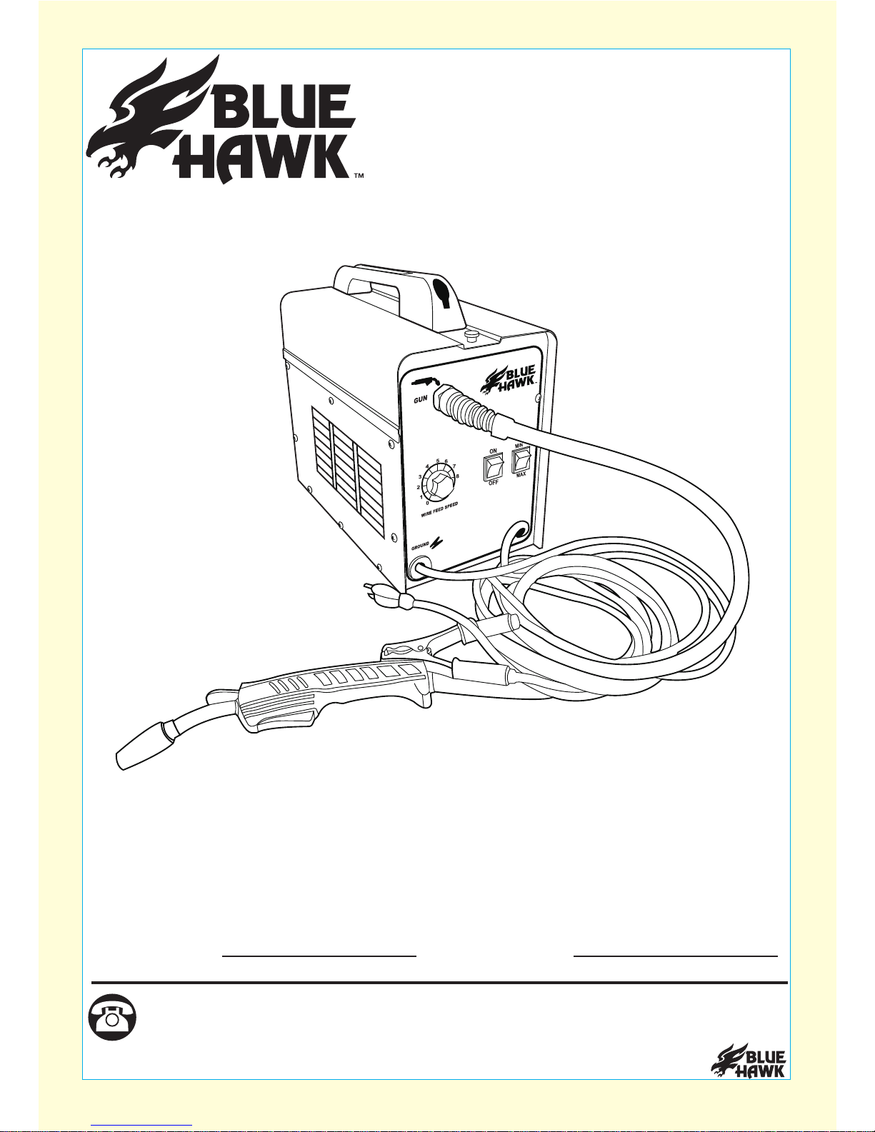
MODEL #SGY-WELDER1
FLUX-MIG 100
Flux-MIG 100
1
service department at 1-877-888-8225, 8 a.m. - 8 p.m., EST, Monday - Friday.
Questions, problems, missing parts? Before returning to your retailer, call our customer
®
www.lowes.com
120 V
60 Hz
20 A
Français p.19
Español p.37

TABLE OF CONTENTS
IMPORTANT
Package Contents ................................................................................................................... 6
Product Specifications ............................................................................................................. 5
Read and follow all safety rules and operating ins
SAVE THIS MANUAL
YOU NEED TO REFERENCE SPECIFIC INFORMATION FROM THIS MANUAL. PLEASE KEEP THIS
MANUAL IN A SAFE PLACE.
tructions before using product. Retain this manual
for future reference.
Preparation/Assembly Instructions
Install Wire Spool............................................................................................................................8
Safety Information.................................................................................................................... 3
Accessory Contents..................................................................................................................7
Routing Wire...................................................................................................................................8
Changing Wire Settings.................................................................................................................10
Different Welding Options
Troubleshooting.................................................................................................................................
Warranty............................................................................................................................................
Replacement Parts List.......................................................................................................................
MIG Welding...................................................................................................................................12
Flux Welding..................................................................................................................................12
Aluminum Welding........................................................................................................................
®
www.lowes.com
2
14
Electrical Schematic Outline..........................................................................................................13
15
17
18

®
www.lowes.com
SAFETY INFORMATION
WEAR PROPER PROTECTIVE GEAR:
Always make sure to wear the proper ANSI approved arc shade eye protection with protective
Failure to use proper eye protection can result is serious eye injury and/or possible blindness.
Always dress properly and wear protective clothing to prevent burns to the body.
Keep loose hair, loose clothing, or any hanging jewelry away from welder and welding area.
lens and a full face shield.
It’s recommended to use welding gloves and a welding apron when possible to prevent burns to
the body and hands from any sparks generated while welding.
Whenever possible, it’s recommended that electrically non-conductive clothing and non-skid
footwear be worn when using tools.
KEEP CHILDREN AWAY FROM WORK AREA AND TOOL:
Keep tool out of reach of children and never allow children to handle equipment or tool.
Never leave the tool unattended when it is plugged into an electrical socket.
Always turn off tool and unplug if you are not using tool, or are leaving the work area, so that
unauthorized users cannot easily operate tool.
WORK ENVIRONMENT HAZARD:
Keep work area clear from clutter and other work hazards.
Do not use this product in unsafe work conditions.
Always operate the tool in clean, well-lit area.
Always make sure that the work area is well-ventilated.
Operating the tool in a cluttered or disorganized work space which is dark is not recommended
and increases the risk of injury.
Follow OSHA guidelines for permissible exposure limits (PEL’s) for various fumes and gasses
that may be generated when welding.
Always be aware of your work area surroundings. It’s recommended that no one be in the work
area when the tool is in use.
While the welder is in use, anyone near the work area should never look directly at the light
Always make sure that there is adequate space to properly use this tool.
Do not operate tool if damaged during shipping and/or handling.
Using a damaged or unsafe tool can result in serious injury, death, and / or property damage.
Make sure that you are ready to work and are ready to operate the item before turning it on.
Always have your face shield and eye protection in place before turning the unit on.
output generated from the welder without proper eye and face protection.
Do not operate this tool in the presence of flammable liquids, gases, or other flammable
materials that are not directly intended to be in the work area and which are not secured.
Be aware of any extension cords and/or air hoses in the work area as they may present a
possible tripping hazard.
If an external gas supply is used in the welding process, make sure it’s safely secured BEFORE
turning the unit on.
FOR YOUR OWN SAFETY, PLEASE READ AND UNDERSTAND THIS ENTIRE MANUAL
BEFORE ATTEMPTING TO ASSEMBLE, OPERATE OR INSTALL THIS PRODUCT. IF YOU
HAVE ANY QUESTIONS PLEASE CALL CUSTOMER SERVICE AT 1-877-888-8225, 8 A.M. -
8 P.M., EST, MONDAY - FRIDAY.
FAILURE TO OBSERVE AND FOLLOW THE SAFETY INSTRUCTIONS AND USER MANUAL
COULD RESULT IN ELECTRICAL SHOCK, FIRE, AND/OR SERIOUS INJURY OR DEATH.
3

®
www.lowes.com
SAFETY INFORMATION
ADDITIONAL ELECTRICAL SAFTEY
Welder must be plugged directly into grounded outlet and NEVER plugged into an extension
cord outlet.
Using an extension cord could result in a shortage to the welder and/or damage to the item,
causing an increased risk of fire and/or property damage.
Improperly connecting the grounding wire can result in the risk of injury, electrical shock, and/or
electrocution or death.
ADDITIONAL SAFETY GUIDELINES
To avoid accidental starting, be sure the power switch is turned off before plugging in.
INHALATION HAZARD
Welding can produce toxic fumes and gases. Exposure to these fumes and gases can increase
the risk of certain cancers such as lung cancer and larynx cancer.
Other diseases have also been found to be linked to the fumes and gases produced by welding,
and whenever possible the use of a respirator and working in a well-ventilated area is highly
recommended.
Always turn off the welder and unplug the unit from the electrical outlet prior to performing any
assembly, maintenance, or service.
Any service done to the welding machine, outside of routing the wire should be performed by
qualified repair personnel. Any service, repairs, or maintenance performed by unqualified repair
technician could result in an increased risk of injury.
Every tool has a unique function and is designed to operate in a specific way.
Only use a tool for its intended function.
Never operate tool if under the influence of drugs or alcohol.
Never operate tool if you are tired, as operator needs to be in control of tool at all times.
It’s always recommended to have a fire extinguisher and first aid kit near the work area.
Do not cut or weld materials that have a combustible coating or combustible internal structure.
Only use parts and accessories recommended by the manufacturer.
It’s recommended that a welding cart be used whenever transporting any external power
source that may be used with the welder.
Always ensure that the unit is turned off and unplugged before trying to move and/or transport
this tool. Do not abuse power cord and do not use tool if power cord is damaged.
Never dispose of hot slag, as it can cause damage to the container in which you place it or
cause a fire. Allow slag to cool before disposal.
Keep proper footing at all times and do not overreach, as slipping, tripping, and/or falling can be
a major cause of serious injury and/or death. Be aware of any cords and/or other items which
may cause you to lose your footing while in the work area or while item is in use.
All local and state electrical ordinances must be followed when using this item.
Check with a qualified electrician if you are in doubt as to whether the outlet is properly grounded.
Do not modify the power cord plug used with the tool and never remove the grounding prong
from the plug.
Do not abuse power cord and do not use tool if power cord is damaged.
Avoid body contact with grounded surfaces such as pipes, radiators, ranges, and refrigerators
when using this item.
Always securely clamp as close as possible to the metal object which is being welded or to the
metal workbench where the object is mounted and electrically connected.
There is an increased risk of electrical shock if your body is grounded.
4

®
www.lowes.com
WARNING
PRODUCT SPECIFICATIONS
IMPROPER OPERATION OR MAINTENANCE OF THIS PRODUCT COULD RESULT IN
SERIOUS INJURY AND PROPERTY DAMAGE OR DEATH. READ AND UNDERSTAND ALL
WARNINGS AND OPERATING INSTRUCTIONS BEFORE USING THIS PRODUCT.
WHENEVER USING TOOLS, BASIC SAFTEY PRECAUTIONS SHOULD ALWAYS BE
FOLLOWED TO REDUCE THE RISK OF PERSONAL INJURY.
YOUR RISK FROM THESE EXPOSURES VARIES, DEPENDING ON HOW OFTEN YOU DO
THIS TYPE OF WORK. TO REDUCE YOUR EXPOSURE TO THESE CHEMICALS WORK IN
A WELL VENTILATED AREA AND WORK WITH APPROVED SAFTEY EQUIPMENT, SUCH
AS SUCH AS A RESPIRATOR OR DUST MASKS WHICH ARE SPECIALLY DESIGNED TO
FILTER MICROSOPIC PARTICLES.
• LEAD FROM LEAD BASED PAINTS
• CRYSTALLINE SILICA FROM BRICKS, CEMENT AND OTHER MASONRY PRODUCTS
• ARSENIC AND CHROMIUM FROM CHEMICALLY TREATED LUMBER
5
SOME DUST CREATED BY PAINT SPRAYING, POWER SANDING, SAWING, GRINDING,
DRILLING, AND OTHER RELATED ACTIVITIES IS KNOWN TO THE STATE OF CALIFORNIA
TO CAUSE CANCER, BIRTH DEFECTS, AND OTHER REPRODUCTIVE HARM. A LISTING
OF CHEMICALS CAN BE OBTAINED FROM www.oehha.ca.gov UNDER PROPOSITION 65.
SOME EXAMPLES OF THESE CHEMICALS ARE:
Welding Current 35 ~ 88 amps
Duty Cycle 30% at 70 amps; 45% at 55 amps
Input Power 120 V AC, 20 amps (max) at 60 Hz
Open Circuit Voltage (max) 34 V DC
Thermal Overload Protection with Light Automatic shutdown and restart after cool down
Wire Size 0.025 to 0.030 in. steel and stainless steel;
0.030 to 0.035 in. flux core and aluminum
Cable Sizes Power: 16 AWG x 3C x 6 ft.
Ground: 8 AWG, 6 ft. (10mm²)
Gun: 8 AWG, 6 ft. (10mm²)
Welding Capacity 1 mm to 1/4 in. steel
Wire Spool Size 2 lb. Spool
Flux-MIG 100
www.lowes.com
6
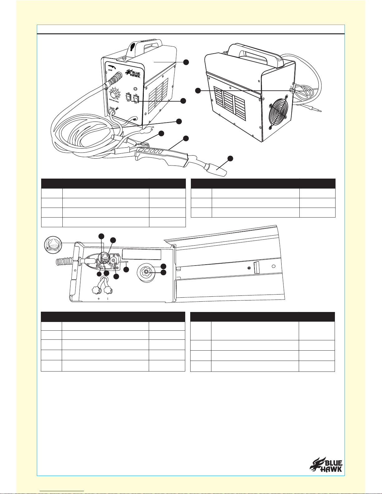
PACKAGE CONTENTS
A Welder 1
11
1
1
1
1
1
1
Power output control dial
Torch Cable
B
C1Gas tube inlet connectionX
1D Gun Nozzle trigger
Torch tip/ Gun nozzle cupE 1Grounding clampV
F Wire feed assembly
Tension adjustment knob
Swing arm
G
H
I Feed tube
Plastic protection cap
J
A
B
C
VD
E
O
N
I
J
L
G
H
X
Part QuantityDescription Part QuantityDescription
Part QuantityDescription
1
1
Feed wire inlet
Wire spool axle
L
N1
Thumb Nut
O
Part QuantityDescription
K
2
Feed wheel Size
(.025, .030, .035)
K
120 V
60 Hz
20 A
®
®
www.lowes.com
7
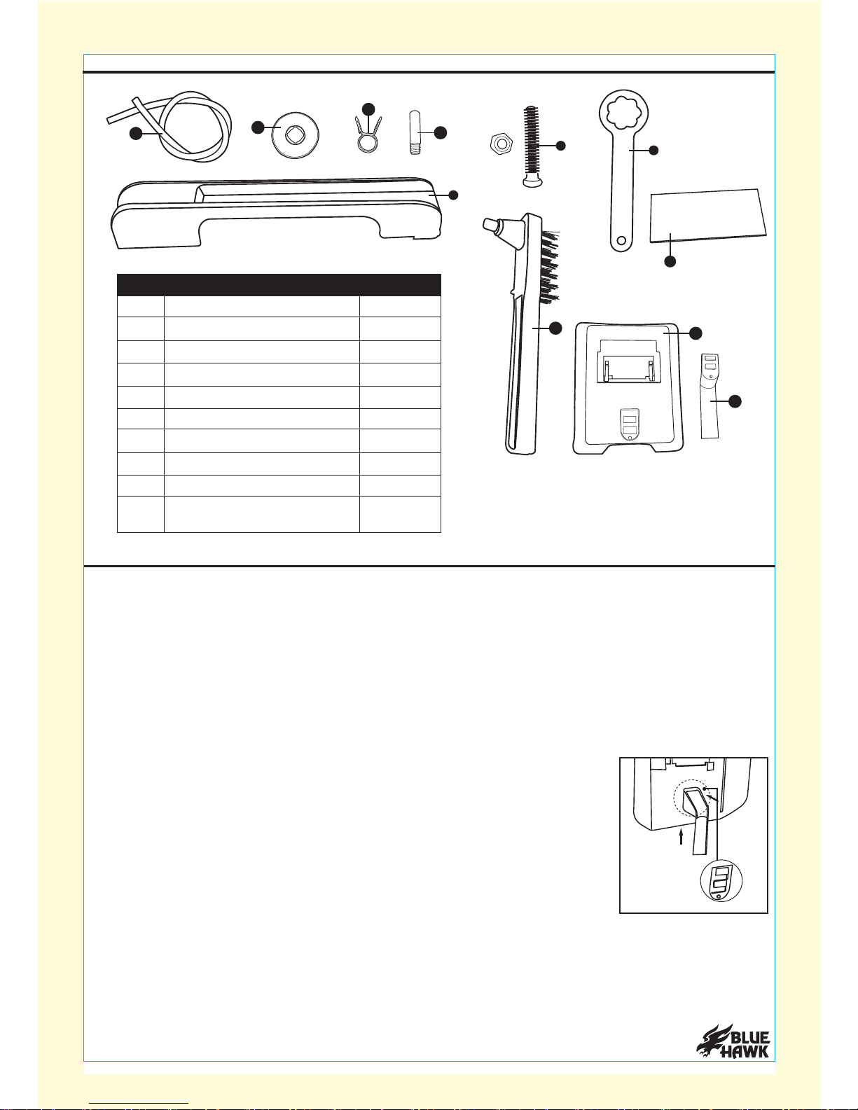
Remove all accessories from top of welder.
Put accessories together so that they are available to use before you begin welding.
Wrench -
Use wrench to tighten or loosen positive and negative terminal outputs. Please see
different welding options section for different configurations of welding terminals.
Contact tips -
See step by step instructions for how to attached tips to gun nozzle. There are
three contact tips provided: 0.025 in., 0.030 in. and 0.035 in.
Gas tube -
Tube that is used to connect an external gas cylinder to the back of the welder.
Please consult your local retailer to see which external gas cylinder is compatible with this
welder. Make sure to secure gas tube (if gas is used) with gas tube safety clip.
Face shield/Welding lens/Face shield handle -
Place the welding lens
on inside of face shield and slide welding lens into place. Make sure that
the welding lens snaps into place where the plastic tabs on the inside hold
there are no gaps in which the lens would not provide the proper eye
protection. Attach the face shield handle by lining up the two slots and
pressing down and up so that the handle locks onto the face shield. DO
PROPER CONTROL OF FACE SHIELD DUING WELDING PROCESS.
PREPARATION
ACCESSORY CONTENTS
2
1
Contact tips
Gas tube
Q
R1Welding lensS 1
1
Face shield
Handle
T
U1
1
1
1
Gas Tube Safety Clip
Hammer
Hand Shank
Hand Shank
screw and nut
W
X
Y
Z
R.025
XD
K
P
Q
э
UV.9XZ1C ,(shade 9) ANSIZ87.1
S
W
U
T
1WrenchP
Part QuantityDescription
the welding lens in place properly. Look at the face shield and make sure
NOT USE FACE SHIELD WITHOUT HANDLE, AS YOU NEED TO HAVE
X
Z
Y

®
www.lowes.com
8
NOTE: Whenever changing welding wire size, you will need to make sure that your contact tip
and feed wheel size match up to your new welding wire size you intend to use for your specific
welding application. If any of the welding components (feed wheel, contact tip, welding wire) are
a different size you should not proceed with the installation process.
Before you start any welding project, make sure the power to the welder is turned off. You will
need to make sure that the feed wheel, contact tip, and welding wire size match before you start
any set up or preparation, and/or before you start any welding project. If any of the welding
components (feed wheel, contact tip, welding wire) are a different size, you should not proceed
with the installation process.
Assembly time:
15-20 minutes depending on the welding application you plan to use with welder.
The welder has initially been set up to operate with flux core wire. Any welding application that
does not use flux core wire will require changes to be made. Please reference ‘Types of welding
applications compatible with welder’ and ‘Changing welding wire size’ sections to see which
welding set up is best suited for your particular welding application.
Tools required for assembly (not included):
Welding wire determined by use (flux core welding
wire or MIG welding wire), pliers, wire cutters, adjustable wrench, hose clamp, shielding gas, and
gas regulator.
NOTE:
If you intend to use a MIG welding application, additional components are required for
proper operation and not included. Please reference the MIG welding section under ‘Types of
welding applications compatible with welder’ and consult with your local retailer for assistance in
selecting components that are suitable for and compatible with your specific welding application.
PREPARATION
This welder allows you 3 different welding options: Flux welding, MIG welding, and aluminum
PLEASE READ AND UNDERSTAND THE SET UP PROCESS FOR EACH WELDING
METHOD BEFORE ASSEMBLING AND USING THE WELDER.
welding. Before you begin welding, first figure out which specific welding application you plan to
use. Follow the specific set up instructions for that specific welding process. Please remember
each welding process requires its own particular requirements and proper set up of welder for
proper operation. Failure to follow the proper set up may result in improper use of the item that
may cause properly damage, electrical shock, fire, and/or serious injury or death.
BEFORE YOU BEGIN WELDING
Welding requires a high degree of skill and experience. Once you have the welder and
accessories properly secured and ready to operate, you should practice a few sample welds
on a scrap piece of metal before you begin welding your first project. Check your power
output and adjust (if needed) so that the proper power output is used for the specific welding
application. Always make sure to check that your work area is safe and secure. Additional
practice periods are recommended whenever you weld a different thickness of metal, different
material, or use a different type of welding wire, or when modifying the electrical connection.
BEFORE BEGINNING ASSEMBLY AND OPERATION OF PRODUCT, MAKE SURE ALL
PARTS ARE PRESENT. IF ANY COMPONENTS LISTED ARE MISSING, PLEASE CONTACT
CUSTOMER SERVICE AT 1-877-888-8225, 8 A.M. - 8 P.M., EST, MONDAY - FRIDAY.
DO NOT USE THE ITEM IF PARTS ARE MISSING.
Grounding clamp -
Grounding clamp is required for proper use of welder. The grounding clamp
needs to be connected to bare metal in order to complete the circuit and for the welder to be used
properly. If the grounding clamp is not connected to a bare metal contact, you will not be able to
complete the circuit. It’s recommended that the grounding clamp is connected as close as
possible to the welding area, but not so close in which the grounding clamp becomes a safety
concern.

®
www.lowes.com
9
Before feeding the welding wire through the wire feed assembly, make sure to securely hold onto
the end of the welding wire while keeping consistent pressure on the welding wire during the
installation process. If consistent tension is not applied on the welding wire, the welding wire can
spring backwards, causing a “bird’s nest” in which the welding wire can bunch together, causing
severe tangling resulting in wasted wire.
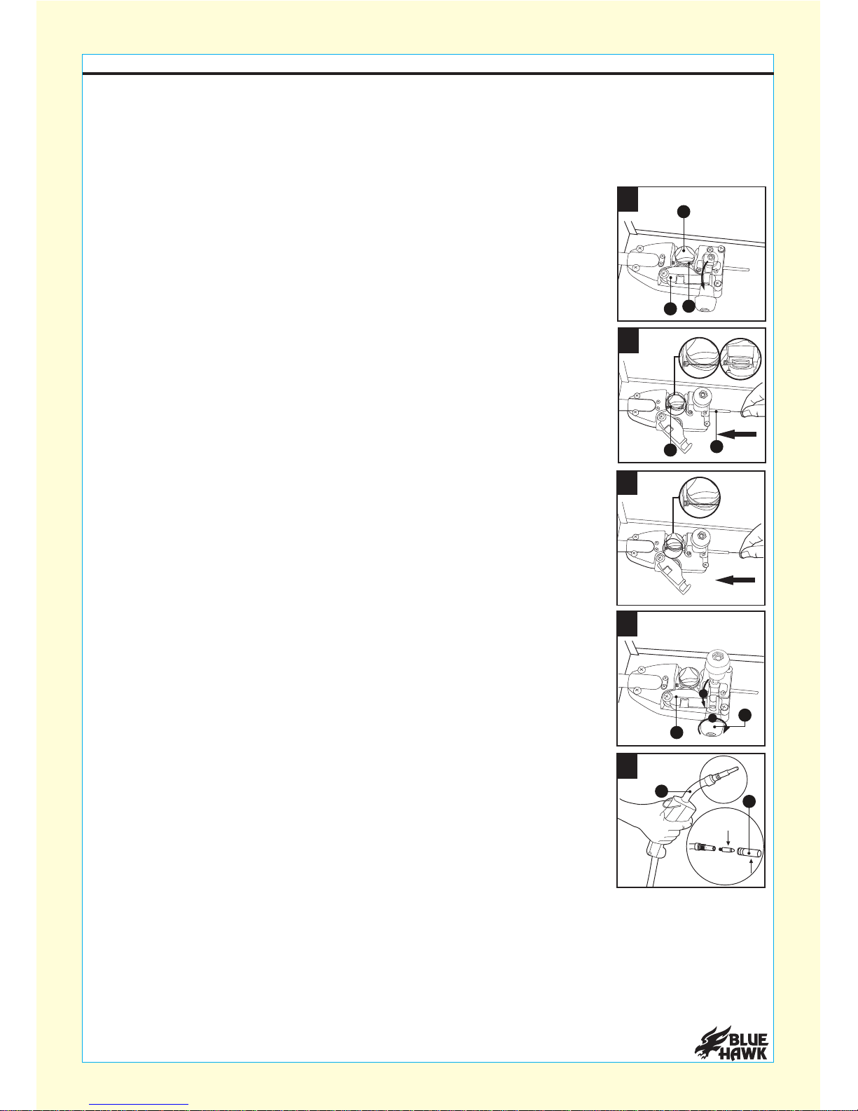
NOTE:Plastic protective cap (J) can only be removed or installed when
no wire is running or installed through feed wheel.
Unscrew plastic protective cap (J) from the feed wheel (K) (turn
counterclockwise to remove) and check the sizing on the feed wheel (K)
(sizing facing up when feed wheel is in place is the size of welding wire
5
Once tension arm is up, open swing arm (H) so that welding wire can be
fed through the wire feed assembly (F).
Loosen the tension adjustment knob by turning it counterclockwise then
lift the tension adjustment arm up. 3
4
H
JK
F
which should be used).
Unscrew safety bolt on top of access panel and lift the access panel
to expose the wire feed assembly.
Unscrew the thumb nut (O) and remove top of spool knob and spring.
Install a 2 lb. spool of welding wire (not included) on the wire spool axle (N).
Secure the spool of welding wire to the wire spool axle (N) using the spring
underneath and the knob on top. Tighten the thumb nut (O) by hand until
only there is a slight resistance when turning the spool.
ASSEMBLY INSTRUCTIONS
2
1
O
N
®
www.lowes.com
10
Make sure the welding wire is being fed through the wire feed assembly properly, and that the
feed wheel and welding spool are both spinning and that the welding wire is not pressed flat. If the
welding wire is being pressed flat, stop the machine and loosen the tension on the tension
adjustment knob. Continue to feed wire through while making sure it’s not being pressed flat.
Once the welding wire is past the welding nozzle tip, turn power off to unit and screw on the
contact tip so that you can properly check the welding wire tension before welding.
NOTE: When unscrewing the gun nozzle cup (E), make sure you do not
damage the ceramic ring at the base of the gun nozzle. Always place gun
nozzle cup in secure place where it can not get damaged.
Unscrew and remove the gun nozzle cup and contact tip (E). Lay out the
torch cable straight. Turn power switch ON and press trigger on the
welding gun to feed wire through the torch cable (C).
10
Continue to feed welding wire through and into the feed wire inlet (L).
Once the wire has been fed into the wire feed inlet (L), close the swing
arm (H) and then lower tension arm and slightly tighten adjustment 9
1
2
8
NOZZLE
CONTACT TIP
knob (G).
H
E
C
G
6
Attach the plastic protective cap (J) over the feed wheel (K). Turn the
plastic protective cap (J) so that the opening is facing the swing arm (H)
when closed and the opening will allow the welding wire to feed through
the wire feed assembly.
Feed welding wire through feed tube (I) and along the top groove of feed
wheel (K).
It’s recommended that the welding wire have a clean, straight cut at the end which will be fed
through the wire feed assembly. Cut off the end of the welding wire with a pair of wire cutters
(not included) to remove any burs, sharp edges, and/or crimps or bends in welding wire. The
manufacturer recommends cutting at least 3 inches from the welding wire to ensure a clean
straight cut.
ASSEMBLY INSTRUCTIONS
7
J
K
KI
H

®
www.lowes.com
11
WARNING AND RISK OF EXPLOSION:
For certain welding applications, the use of shielding gas may be required.
Flammable gas is dangerous. Make sure that the bottle or cylinder of gas is properly secured
before you operate this tool. If improper transportation of external gas cylinder occurs, it can
result in the bottle or cylinder being damaged or ruptured, which may cause an explosion,
causing SEVERE PERSONAL INJURY AND/OR DEATH.
Once the welding wire is properly secured, loosen the thumb nut to remove the welding wire
spool from the wire spool axle. Loosen the tension adjustment knob by turning it
counterclockwise and raising up the tension adjustment knob.
The manufacturer recommends the use of pliers (not included) when pulling the excess welding
wire from the unit. From torch tip end, pull excess welding wire out of welder gradually. Once all
the excess welding wire has been removed, follow the ‘Assembly Instructions’ on how to properly
feed the new welding wire through the welding machine properly.
Before you begin welding, please review the sticker on the inside of the access panel to make
sure the proper polarity has been set with the type of welding application and welding
wire you intend to use. Please also review the ‘Different Welding Options’ section of the
instruction manual for additional information as to which polarity may be best suited for specific
welding applications. Once the proper tension and polarity is set, close the access panel and
tighten access panel with safety screw.
WARNING: Before making any changes on the welder, make sure that the power is turned off
and the welder is unplugged from the electrical outlet.
Unscrew the safety screw on top of welder and open access panel. Once
access panel is open, cut the welding wire a few inches away from the
welding wire spool with a pair of wire cutters (not included). Make sure to
hold onto the end that is still connected to the welding wire spool and keep
constant tension on the welding wire end to prevent the welding wire from
unraveling, causing a "bird's nest." Place the welding wire end into one of
the holes on the top of the welding wire spool.
11
CHECKING WELDING WIRE TENSION:
To obtain the proper tension on the welding wire, turn the power back on and feed the welding
wire through the torch tip. Place a piece of scrap wood 2 - 3 inches away from the torch tip end
and continue to feed the welding wire through until the welding wire comes into contact with the
piece of scrap wood. For proper tension, the welding wire should bend when coming into contact
with the spare piece of wood.
If the welding wire bends, turn power off to the unit, cut off the bent piece of welding wire with wire
cutters (not included), and screw on the gun nozzle cup on by hand, making sure to not damage
the ceramic ring. Also do a final check to make sure the contact tip size you intend to use matches
both the welding wire and feed wheel size.
ASSEMBLY INSTRUCTIONS
CORRECT TENSION:
If the welding wire comes to a stop when coming into contact with the spare piece of wood,
rewind the welding wire on the spool very slightly by hand and add some additional tension to
the tension adjustment knob. Make sure the welding wire is taunt. Once welding wire is taunt,
again feed the welding wire through the machine. Check that the welding wire is not flattened
with the additional tension added to the tension adjustment knob. Repeat the above process until
the welding wire bends when coming into contact with the spare piece of wood.
INCORRECT TENSION:
If changing welding wire size, make sure that the new welding wire matches the feed wheel and
contact tip size.
CHANGING WELDING WIRE SIZE:
®
www.lowes.com
12
ASSEMBLY INSTRUCTIONS
BEFORE YOU CAN BEGIN WELDING MAKE SURE ALL PROPER SAFETY EQUIPMENT IS
BEING WORN. IF SAFTEY EQUIPMENT IS NOT WORN DO NOT PROCEED TO USE THE
WELDER AS IT PRESENTS A HAZARD. ALWAYS MAKE CERTAIN THAT YOUR GROUNDING
CLAMP IS SECURELY PLACED IN A SAFE POSITION AND IS IN DIRECT CONTACT WITH
BARE METAL. MAKE CERTAIN THAT YOU HAVE READ ALL THE INSTRUCTION
PROCEDURES BEFORE YOU BEGIN ANY WELDING PROJECT.
EACH WELDING PROJECT CAN BE DIFFERENT, REQUIRING ITS OWN UNIQUE SET UP
AND USE OF VARIOUS POWER OUTPUT LEVELS. PLEASE CONSULT YOUR LOCAL
RETAILER IF YOU ARE UNSURE WHICH SET UP AND POWER OUTPUT MAY BE
BEST SUITED FOR YOUR PARTICULAR WELDING APPLICATION.
WARNING: THIS WELDING MACHINE MUST BE CONNECTED TO A POWER SOURCE IN
ACCORDANCE WITH APPLICABLE ELECTRICAL CODES. PLEASE CONSULT A QUALIFIED
The United Stated National Electrical Code (Article 630-B, 1990 Edition) provides standards for
amperage handling capability of supply conductors based on duty cycle of the welding source.
If there is any question about the installation meeting applicable electrical code requirements,
please consult a qualified electrician
WARNING: Each specific welding application (flux welding, MIG welding, aluminum welding)
requires a specific set up of the terminal outputs in order to achieve a proper weld. Failure to set
up the welding terminal outputs properly can result in an improper weld or potential damage to
the work area. Once you know which welding process you intend to follow, review the welding
wire label for proper polarity set up. Also refer to the welding polarity sticker on the inside of the
access panel for a quick reference for proper set up.
TYPES OF WELDING APPLICATIONS COMPATIBLE WITH WELDER
ELECTRICIAN.
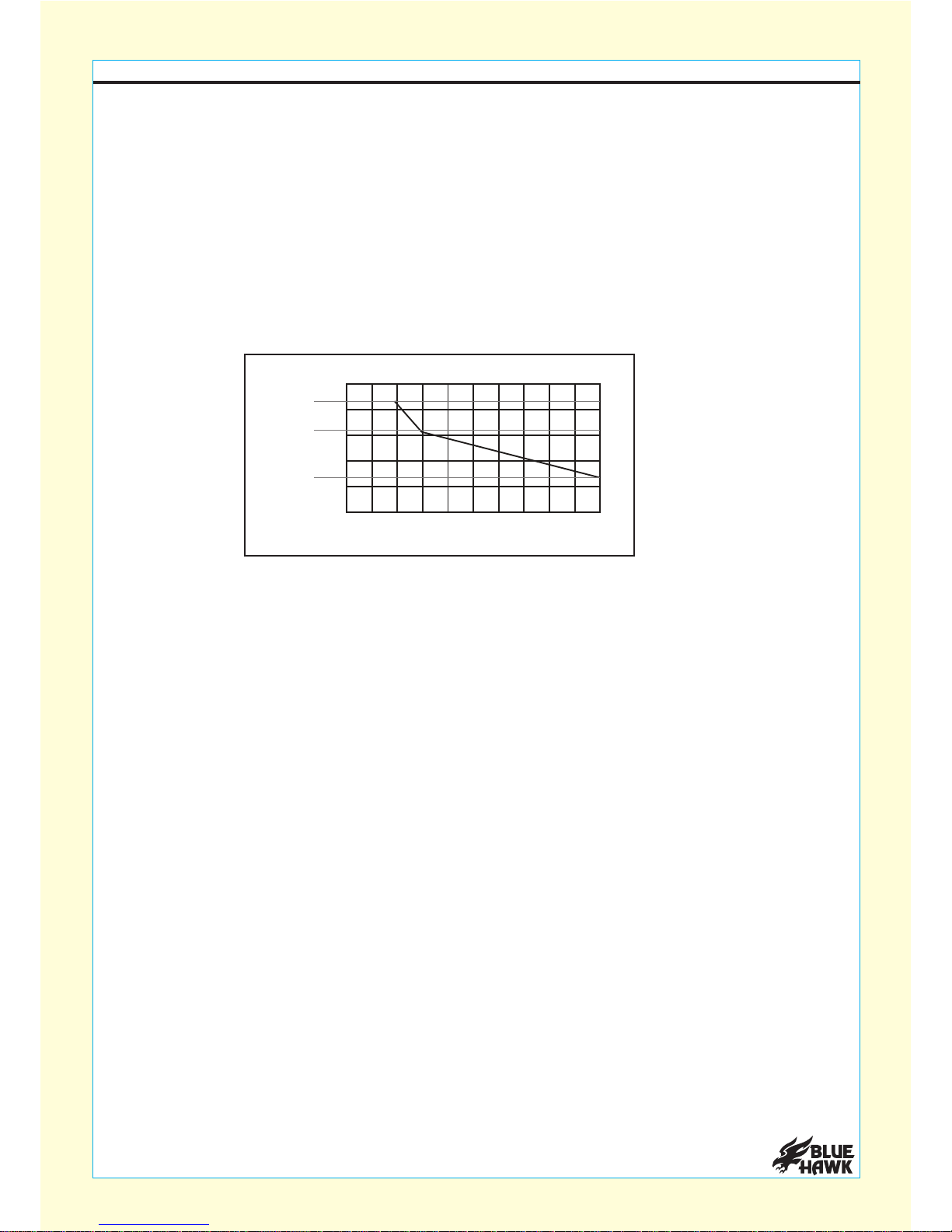
Avoid damage to the welder by not having the unit on for more than the recommended duty cycle
time.
CAUTION
DUTY CYCLE GRAPH
Max
Min
Duration of Use
Amperage
Switch Settings
88
70
66
55
35
300 100908070605040302010
The duty cycle defines the number of minutes, within a 10 minute period, during which a given
welder can safely produce a particular sustainable welding current. Failure to follow the duty cycle
limitations and not allowing the unit to cycle properly can overstress the welder's power
generation system, contributing to an improper and premature welder failure.
DUTY CYCLE
NOTE: This welder is equipped with an internal protection system to help prevent overstress on
the unit. When the unit overheats or the duty cycle/duration is not followed, the welder will
automatically shut down and automatically power back up after it has cooled. Once the unit is
powered back up, follow a more conservative duty cycle routine to help prevent excess wear and
strain on welder.
®
www.lowes.com
13
Additional components needed for MIG welding:
• Bottle or cylinder of argon gas or CO2. Must be compatible with the bottle or cylinder you intend
to use and meet all local and state safetyregulations.
• Adjustable wrench: Used to properly secure the regulator (regulator nut) on the bottle or
cylinder of CO2or argon gas (shielding gas).
• MIG welding wire: Consult your local retailer for information on which welding wire is best
suited for your specific welding application.
• Safety chain: Consult your local retailer for information on which safety chain/securing
device is best suited for the bottle or cylinder you plan to use for your specific welding
application. Please make sure that all local and state safety regulations are followed so that
you can properly secure your external gas supply.
• Welding cart: Must be used for proper transportation of welding tool and any bottle or cylinder
used with this item. Please reference your welding car’s instruction manual to make sure your
welding cart is capable of transporting the size of bottle or cylinder you intend to use.
NOTE: Any bottle or cylinder must meet all local and state safety regulation standards.
• Gas regulator: Must be used whenever an external gas supply is used. Make certain that any
regulator used is compatible with the external bottle or cylinder you intend to use and the
regulator meets all local and state safety regulations. It’s recommended that any gas regulator
which is used have a plastic adapter washer seated in the fitting that attaches to the bottle or
cylinder you intend to use for your specific welding application.
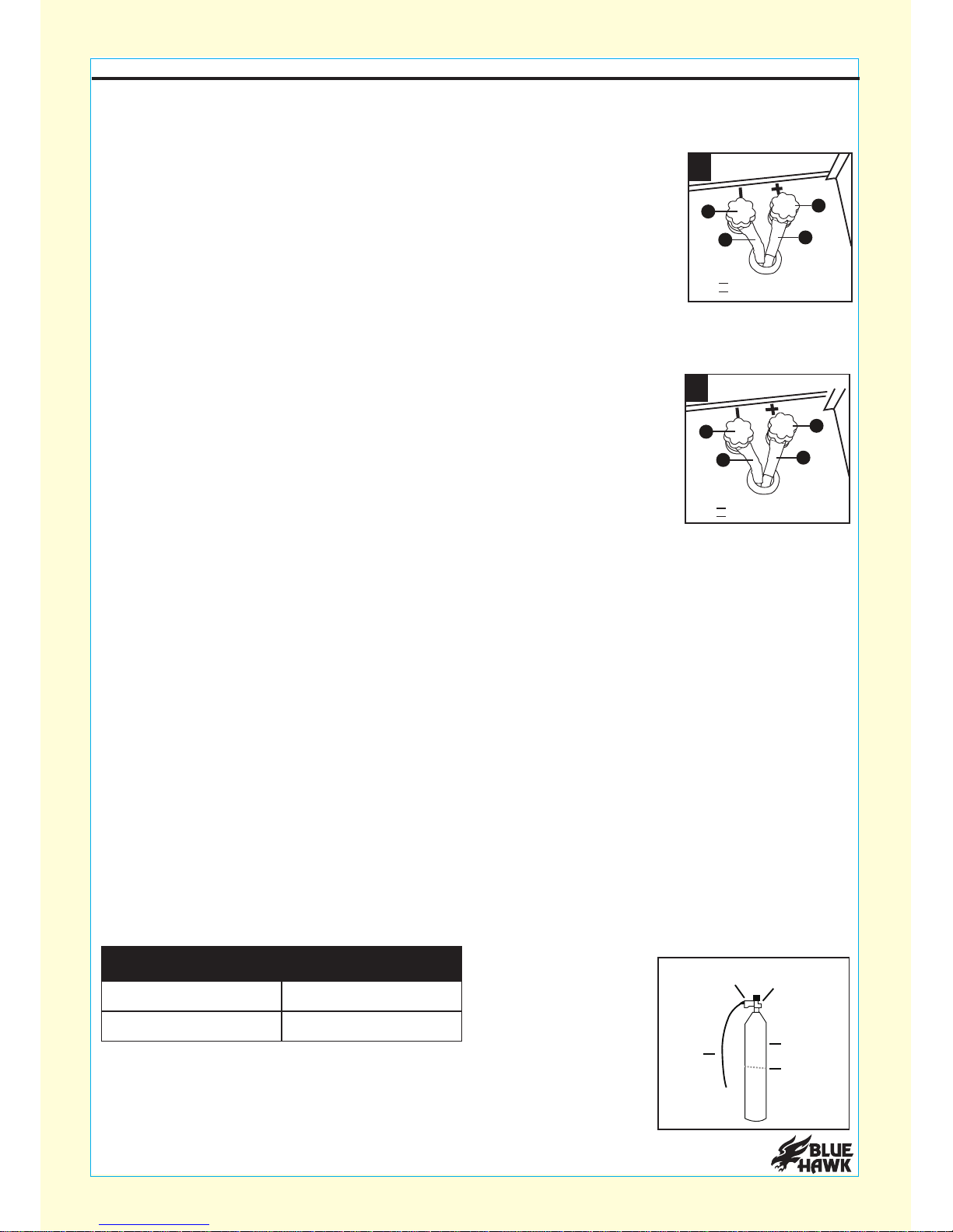
If you intend to use this welder with flux wire (flux welding), set up the polarity as follows:
After the polarity has been set up properly, plug the power cord into its 120
volt, grounded electrical outlet. Turn the welder ON. Point the gun nozzle
handle away from all objects. Squeeze trigger switch on the gun nozzle
until the welding wire feeds through the tip of the nozzle handle (about 2
inches). If necessary, move the nozzle handle slightly in a circular motion
to help feed the welding wire properly out of the head of the nozzle.
• Black (negative) wire is connected to red (positive) terminal connection on welder.
• Red (positive) wire is connected to black (negative) terminal connector
on welder.
Flux Welding:
If you intend to use this welder with MIG wire (MIG welding), set up the polarity as follows:
All of the below listed components are not included but are required for
proper instillation and set up for use when MIG welding. If any of the
below components are not used, you should not proceed with any MIG
welding application. Please consult your local retailer for further
assistance.
• Black (negative) wire is connected to black (negative) terminal connection on welder.
• Red (positive) wire is connected to red (positive) terminal connector
on welder.
MIG Welding:
12
Black B
Red R
B
B
R
R
13
Black B
Red R
B
R
R
B
ASSEMBLY INSTRUCTIONS
To properly secure the external bottle or cylinder, a safety chain must
be used to secure the bottle or cylinder to a wall or other stationary/
stable support. Once the bottle or cylinder is properly secured, check
that the safety chain is secured and would prevent the bottle or
cylinder from tipping or falling over. Insulate the base of cylinder from the work ground.
Carbon Steel
Low Alloy Steel
CO or Argon/CO2 2
CO or Argon/CO
2 2
MATERIAL GAS
REGULATOR CYLINDER VALVE
GAS TUBE
GAS CYLINDER
SAFETY CHAIN
®
www.lowes.com
14
ASSEMBLY INSTRUCTIONS
There are some applications for aluminum welding which can allow either polarity set up. Please
consult your local retailer for additional information or review your welding wire label for proper
polarity set up that may be needed.
Aluminum Welding:
Aluminum welding can also be done with the use of shielding gas and with the proper aluminum
wire or flux core aluminum wire. Please consult your local retailer for information on which welding
wire is best suited for your specific welding application.
Once the bottle or cylinder is safely secured, remove the cylinder cap with an adjustable wrench
and place in a secure location away from the cylinder valve and regulator. Open the cylinder
valve very slightly for a very short period (under 3 seconds) and close. This will clear any
dust and/or debris which may have accumulated in the valve outlet. Before proceeding to
hook up the gas tube, make sure the cylinder valve is completely closed and that no gas is
leaking from the valve.
WARNING: THE GAS IN THE BOTTLE OR CYLINDER IS UNDER EXTREME PRESSURE.
BE SURE TO KEEP YOUR FACE AWAY FROM THE VALVE OUTLET WHEN INITIALLY
OPENING. Always make sure to stand to the side of the cylinder valve opening and never stand
directly in front or behind of where the gas is released from the cylinder valve.
Attach one end of the gas tube from outlet fitting on the bottle or cylinder. Secure the gas hose
with hose clamp. Place the gas tube safety clip on the very end of the gas tube inlet connection.
Once gas tube safety clip is in place, squeeze the gas tube safety clip and connect the end to the
gas tube into the gas tube inlet connection located on the back of the welder. Release the gas
tube safety clip to properly secure the gas tube in place. Check the gas tube at both connections
to ensure a proper secure fit and that there are no kinks or twists in the gas hose.
CONNECTING EXTERNAL GAS SUPPLY WITH WELDER
1 2 43
A
B
C
D
4
321
D
C
B
A
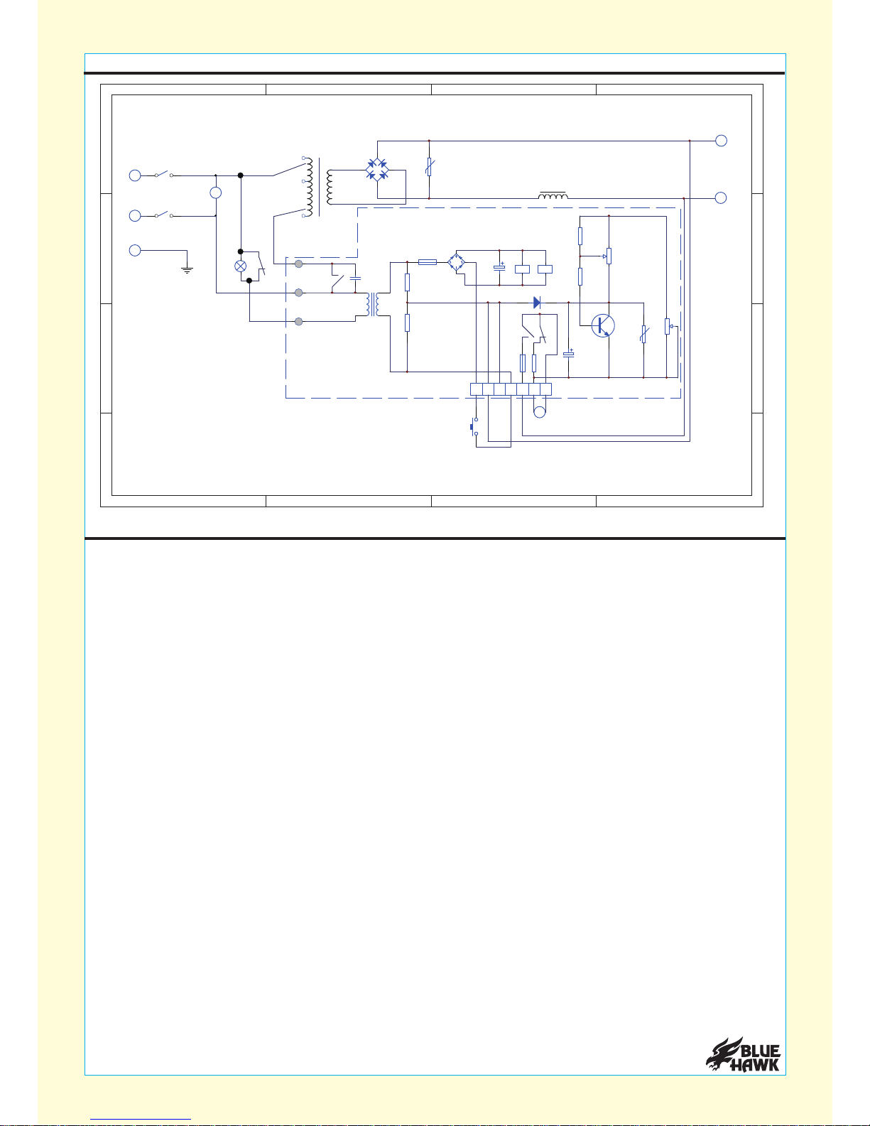
FM
L1
/
+
S1
S1
N
L
C2 CR1 CR2
12 34567 CN1
TS
M
CR1
CN4
CN3
CN2
AC120V 60Hz
ELECTRICAL SCHEMATIC OUTLINE

www.lowes.com
15
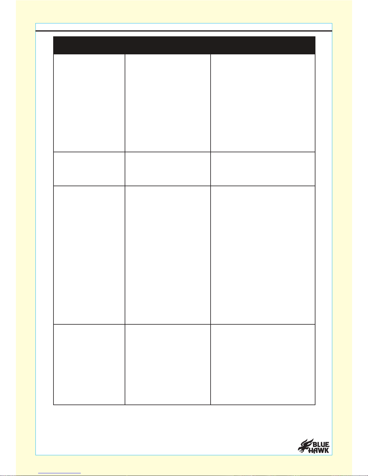
3. Adjust wire feed speed to
achieve a more stable arc.
Welding arc not stable.
1. Wire not feeding
properly.
2. Incorrect contact tip
size.
3. Incorrect wire feed
speed.
4. Loose torch cable or
ground cable.
5. Damaged torch or
loose connection within
torch.
1. See Troubleshooting section
above.
2. Replace with the proper tip
for the wire size used.
4. Check to ensure that all
connections are tight.
5. Have a qualified technician
inspect and repair/replace
as necessary.
TROUBLESHOOTNG
1. Insufficient wire
pressure.
1. Adjust wire feed pressure
properly; follow instructions
on page 12 -13.
2. Replace with the proper wire
feed roll size; follow wire
settings instruction on page
8 to 9.
3. Have a qualified technician
inspect these parts and
replace as necessary.
4. Turn off the unit and match
contact tip size to feed
wheel and welding wire.
2. Incorrect wire feed
roll size.
3. Damaged torch, cable
or liner assembly.
4. Incorrect contact tip
size.
Wire feed motor
runs but wire
does not feed
properly.
PROBLEM POSSIBLE CAUSE CORRECTIVE ACTION
Wire creates a bird’s
nest during operation.
1. Excess wire feed
pressure. 1. Adjust wire feed pressure
properly; follow instructions
on page 12 -13.
2. Replace with the proper tip
for the wire size used.
3. Loosen gun securing bolt
and push gun end into
housing just enough so that
it does not touch wire feed
mechanism.
4. Have a qualified technician
inspect and repair/replace
as necessary.
2. Incorrect contact tip
size.
3. Gun end not inserted
into drive housing
properly.
4. Damaged liner.
CARE AND MAINTENANCE
Store tool in a dry and safe place, out of the reach of children.
The manufacturer recommends the only service that should be done by the consumer should be
routing the welding wire and setting up the welder for the various welding types which the
machine can perform. Any additional maintenance and/or service should be performed by a
qualified repair/service professional. Any service, repairs, or maintenance performed by an
unqualified repair/service professional could result in injury. Consult your local retailer
regarding maintenance questions.
®
www.lowes.com
16
Wire feeds but arc
does not ignite.
Wire feeds but
shielding gas does
not flow.
1. Make certain that the
workpiece is contacted
properly by the ground clamp
and that the workpiece is
properly cleaned near the
ground clamp and the
welding location.
2. Verify that contact tip is the
proper size for the welding
wire used. Check that the
hole the tip is not deformed
or enlarged. Also, check that
the tip is not dirty; this would
prevent a good connection.
If needed, replace contact
tip with proper size and type.
1. Improper ground
connection.
1. Empty gas cylinder.
2. Nozzle plugged.
3. Regulator or cylinder
valve closed.
4. Gas line blocked.
5. Gas solenoid broken or
not connected properly.
1. Check gas cylinder.
2. Clear nozzle. If damaged,
replace.
3. Make sure both valves are
adjusted properly.
4. Check external hose and
hose within torch cable.
5. Have a qualified technician
check/replace.
2. Improperly sized or
excessively worn
contact tip.
TROUBLESHOOTING
2. Have a technician check and
secure/replace switch body.
3. Have a qualified technician
check/replace.
Welder does not
function when
switched on.
1. Tripped thermal
protection device.
2. Faulty or improperly
connected with switch
body.
3. Internal fuse blown.
1. Shut the welder’s switch to
off and allow it to cool for at
least 20 minutes. Reduce
duration or frequency of
welding periods to help
reduce wear on the welder.
Refer to duty cycle graph.
Weak arc strength. 1. Incorrect line voltage. 1. If insufficient, have a licensed
electrician remedy the
situation.
PROBLEM POSSIBLE CAUSE CORRECTIVE ACTION

®
www.lowes.com
17
WARRANTY
1-YEAR LIMITED WARRANTY
The manufacturer warrants this product against defects in materials and workmanship for
one year from date of purchase. If within this period a product is found to be defective in
material or workmanship, the product must be returned with a copy of the bill of sale as proof
of purchase to the place of purchase. The manufacturer will, at its option, repair, replace or
refund the purchase price to the consumer. This warranty does not cover the product becoming
defective due to misuse, accidental damage, improper handling and/or installation and specifically
excludes liability for direct, incidental or consequential damages. As some states do not allow
exclusions or limitations on how long an implied warranty lasts, the above exclusion and limitation
may not apply to you. This warranty gives you specific rights and you may also have other rights
which vary from state to state.

®
www.lowes.com
18
REPLACEMENT PARTS LIST
QUANTITYDESCRIPTIONPART
11
2
Pull not to take off
2
3
Ground forceps
1
4
Welding pistol
4
5
Spring pull not to take off
Power switch
1
6
7
Wire Feed Speed
Control Knob
1
1
8
Current switch
1
9
Overload indicator lamp
1
10
Front panel
1
11
Baseplate
1
12
Bottom bead
Mesh enclosure
Admission piece
1
13
14
15
Fan
1
1
1
Plug cord
QUANTITYDESCRIPTIONPART
16 1
17
PCB
1
18
Rectifier
1
19
Main transformer
1
20
Overheat protector
Wire feed disc shaft
1
21
22
Wiring terminal
2
1
23
Clapboard
1
24
Right lateral plate
1
25
Silk plate
1
26
Motor
1
27
Nut
Cover
Hand shank
1
28
29
30
Left lateral plate
1
1
1
Ductance
Printed in China
BLUE HAWK
is a registered
trademark of
L. F., LLC. All
Rights Reserved.
R
Flux-MIG 100
JOIGNEZ VOTRE REÇU ICI
Numéro de série Date d’achat
ARTICLE #0425019
MODÈLE #SGY-WELDER1
FLUX-MIG 100
19
au détaillant, appelez notre service à la clientèle au 1 877 888-8225, entre 8 h et 20 h
Des questions, des problèmes, des pièces manquantes? Avant de retourner l’article
®
www.lowes.com
120 V
60 Hz
20 A
(HNE), du lundi au vendredi.
TABLE DES MATIÈRES
IMPORTANT
Contenu de l’emballage ........................................................................................................... 24
Caractéristiques du produit ...................................................................................................... 23
Avant d’utiliser cet article, lisez et suivez toutes les consignes de sécurité et le mode d’emploi.
CONSERVEZ CE MANUEL
VOUS DEVEZ VOUS REPORTER AUX RENSEIGNEMENTS PRÉCIS DU PRÉSENT MANUEL.
VEUILLEZ CONSERVER CE MANUEL EN LIEU SÛR.
Veuillez conserver ce manuel pour vous y référer ultérieurement.
Instructions pour la préparation et l’assemblage
Installation de la bobine de fil .........................................................................................................26
Consignes de sécurité.............................................................................................................. 21
Accessoires inclus ....................................................................................................................25
Acheminement du fil .......................................................................................................................26
Modification des réglages du fil ......................................................................................................28
Différentes options de soudure
Dépannage .........................................................................................................................................33
Garantie ..............................................................................................................................................35
Liste des pièces de rechange .............................................................................................................36
Soudure MIG .................................................................................................................................31
Soudure à fil fourré ........................................................................................................................31
Soudure à l’aluminium ...................................................................................................................32
®
www.lowes.com
20
Schéma électrique .........................................................................................................................32
Table of contents
Languages:
Popular Welding System manuals by other brands

Swagelok
Swagelok 8HPH Series user manual

Lincoln Electric
Lincoln Electric TOMAHAWK 375 AIR Operator's manual

Miller
Miller SuitCase 8VS owner's manual

GYS
GYS GYSPOT P230 instruction manual

Migatronic
Migatronic SIGMA2 300 STBOFF SHORE user guide

Koike Sanso Kogyo
Koike Sanso Kogyo WEL-HANDY MINI Operation manual


