6Series 8HPH Weld Head User’s Manual
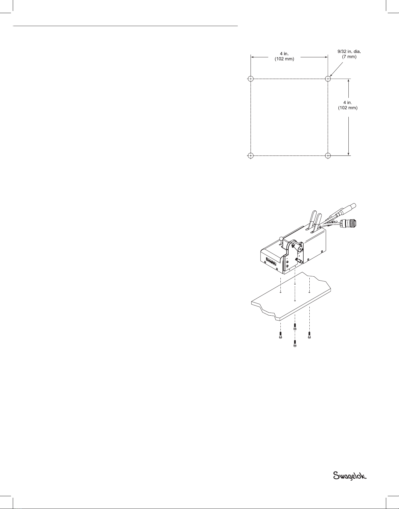
Installing the Weld Head
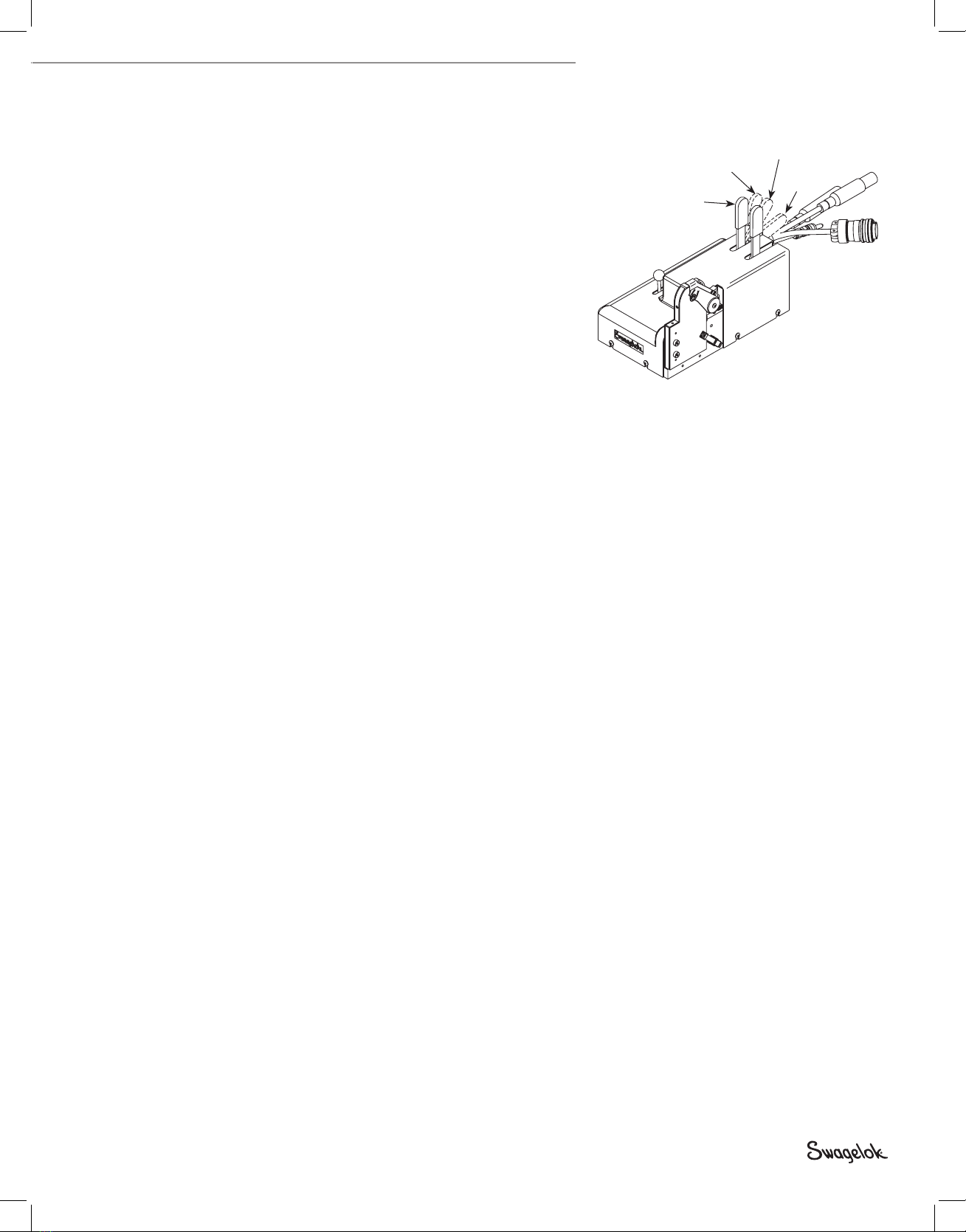
Connecting the Extension Cable to the Weld Head
The four connectors on the cable are:
• threaded multi-pin connector
• electrode (red)
• work (green)
• weld head shielding gas
1. Align the notch on the threaded multi-pin connector of the weld
head cable with the small tab in the mating socket of the extension
cable. Insert the threaded connector and screw on the weld head
cable by turning clockwise until it is tight.
2. Align the arrow on the female socket of the weld head electrode
cable (red) with the arrow on the male connector (red) of the
extension cable. With the arrows aligned, insert and fully seat the
red male connector of the extension cable into the red female
socket of the weld head cable. Twist the connector one-quarter
turn clockwise to lock into place.
3. Align the arrow on the male connector of the weld head work
cable (green) with the arrow on the female socket (green) of the
extension cable. With the arrows aligned, insert and fully seat the
green male connector of the weld head cable into the green female
socket of the extension cable. Twist the connector one-quarter
turn clockwise to lock into place.
4. Insert the male shielding gas connector of the weld head cable into
the female Swagelok quick-connect body of the extension cable.
Align bodies and stems when coupling or uncoupling.
Figure 5 Connecting the Weld Head
to the Extension Cable
Caution!
Do not rotate quick-connects while
coupled. Do not insert foreign
object into uncoupled bodies or
stems.
Figure 6 Connecting the Weld Head to the
Extension Cable
13-170.indb 6 2/1/13 1:45 PM