Blue Ox BX2227 User manual

Page 1 of 7 292-6042 Rev. F 2/14/11
Please read BOTH these Installation Instructions and the General
Instructions before attempting to install or operate this equipment.
1. Blue Ox®towing products and accessories
are intended to be installed by Blue Ox®
Dealers who are familiar with our products and
have the equipment necessary and knowledge
to do “t work”. When necessary Blue Ox®
Dealers can be found at www.blueox.com or
by contacting our Customer Care
Department at (402) 385-3051.
2. Many Blue Ox®Baseplates are designed to
use existing holes and hardware to mount
the baseplate to the towed vehicle. Even
though bolts are there, do not assume they
are adequate for baseplate mounting. Always
use hardware supplied in the hardware kit
and existing hardware specied in the
Baseplate Installation Instructions.
Conrm the towability and pre-towing
procedures for your vehicle with
the owner’s manual or contact the
vehicle’s manufacturer for specic
towing procedures.
Attachment Tab Height: 25.5”
Attachment Tab Width: 24”
2003-05 Honda Pilot
Installation Instructions
BX2227
Bolt Size Grade 5 Grade 8
1/4” 10 14
5/16” 19 29
3/8” 33 47
7/16” 54 78
1/2” 78 119
5/8” 154 230
Bolt Torque Specications
Torque in Foot-Pounds for Inch Bolts
Bolt Torque Specications
Torque in Foot-Pounds for Metric Bolts
Bolt Size Grade 8.8 Grade 10.9
6MM 6 8
8MM 16 22
10MM 31 40
12MM 54 70
14MM 89 117
Serial Number
!
Failure to read and follow these instructions
could result in separation of the towed vehicle
from the tow bar, causing property damage,
loss of towed vehicle, personal injury or death.
WARNING
If the front of your vehicle looks different
than this, call us at (402) 385-3051.

Page 2 of 7 292-6042 Rev. F 2/14/11
Parts List
Ref. No. Qty. Part # Description
1 1 61-5808 Weldment, Baseplate, BX2227
2 4 61-5589 Weldment, 3/8-16 Nut plate
3 4 61-5208 Weldment, Nut Plate, 1/4X1X1, 3/8”/14”Wire
4 2 102-6682 Backing, Plate, BX1015
5 12 201-0440 3/8-16 x 1 1/2” Hex Bolt, Grd. 5, ZP
6 12 203-0010 3/8 Lock Washer, ZP
7 12 203-0003 3/8 Flat Washer, ZP
8 4 202-0003 3/8-16 Hex Nut, ZP
9 4 201-0446 8MM-1.25 x 30MM, Hex Bolt, Grd. 8.8, ZP
10 4 203-0102 8MM Lock Washer, ZP
11 2 201-0979 #12-14 x 1” Self Drilling Screw, ZP
12 2 201-0192 #10-32 X 1/2” Slot, Rd. Hd. Screw
13 2 203-0054 #10 Lock Washer
14 2 202-0047 #10-32 Hex Nut
15 2 101-5822 Adapter, 4 Way Connector
16 2 62-3468 Attachment Assembly, SF/SB (R)
2 226-0046 Baseplate Safety Cable, 36” CL III (Not Shown)
2 229-0359 Quicklink, 3/8, ZP (Not Shown)
2 290-0437 Cap Plug, Black (Not Shown)
Important:
Use only genuine factory replacement parts on your baseplate. Do NOT substitute homemade or non-typical parts. If a bolt is lost or in
need of replacement, for your safety and the preservation of your baseplate, be sure to use a replacement bolt of the same grade (In most
cases it will be Grade 5, please reference the parts list above). Replacement parts may be ordered through your nearest Blue Ox® Dealer or
Distributor, or call our Customer Care Team at (402)385-3051. Failing to follow and/or altering these installation instructions in either
installation or required equipment will void the manufacturer’s warranty.
Tools Required
8MM Socket
10MM Socket
12MM Socket
13MM Socket
13/32” Drill Bit
Vise Grips
LOCTITE Red
2003-05 Honda Pilot
Installation Instructions
BX2227

Page 3 of 7 292-6042 Rev. F 2/14/11
Removable Tabs:
Due to the design of the removable tabs,
the RangeFinder II tow bar can not be used.
Adapters, except for the BX8833 and the
BX88151, can not be used with this baseplate.
Instructions:
The front fascia, headlight assemblies and
metal bumper are removed and reinstalled for
the baseplate installation. Drilling is required.
Models with fog lights may need to be trimmed
on the back side of the fog light housing.
The dimensional variations between otherwise
identical vehicles can be considerable.
While the baseplate was designed for easy
installation, it may be necessary to tailor the
baseplate slightly to compensate for auto
manufacturer’s tolerances. These minor
adjustments may include ling a hole slightly,
bending electrical rods or bending end plates.
The BX8869 Bulb and Socket Wiring Kit is
available for this vehicle.
1. Remove thirteen pushpins on the top side of
the fascia just above the headlight assemblies.
Set pushpins aside to be reinstalled later.
1
2. Use the 8MM socket to remove a metric bolt
from the corner of the fascia just above the
front tire. Do this to both sides of the vehicle.
Set bolts aside to be reinstalled later.
2
2003-05 Honda Pilot
Installation Instructions
BX2227
Installation Instructions
Possible location for the
BX8869 Bulb and Socket Wiring Kit.
Handling of some cosmetic parts
when installing this product may
require the use of protective covers,
rags, specialty tools, etc. to prevent
damage.

Page 4 of 7 292-6042 Rev. F 2/14/11
3. Just forward of the front tire there are two
metric bolts to remove from the underside of
the fascia corner with the 10MM socket. Do
this on both sides of the vehicle. Disconnect
the electrical connections from the fascia.
Pull the fascia’s corner out to the side, then
forward to release and set bolts and fascia
aside carefully to be reinstalled later.
NOTE: Some 2005 models may have four
push pins from the bottom edge of the fascia
to remove before the fascia is removed.
3
4. Using the 10MM socket, remove the ve
metric bolts from the driver’s side headlight
assembly, pull assembly forward, unplug
electrical connections and set aside to be
reinstalled later. Do this to both sides of the
vehicle.
4
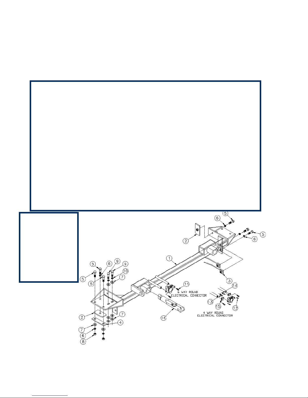
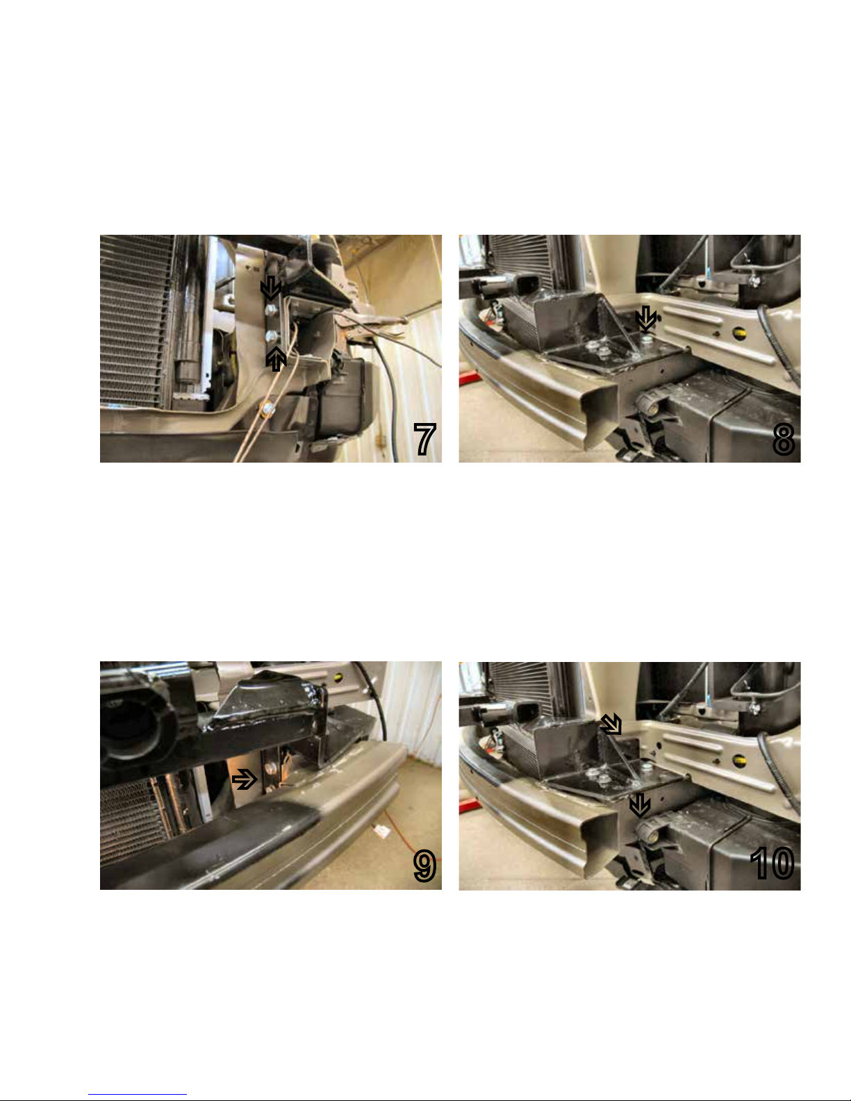
5. Remove the two metric bolts on the top of
the metal bumper bracket using a 12MM
socket. These bolts will NOT be reused for the
installation.
5
6
2003-05 Honda Pilot
Installation Instructions
BX2227
When using power drills be aware
of the dangers of torque and drill bit
length.
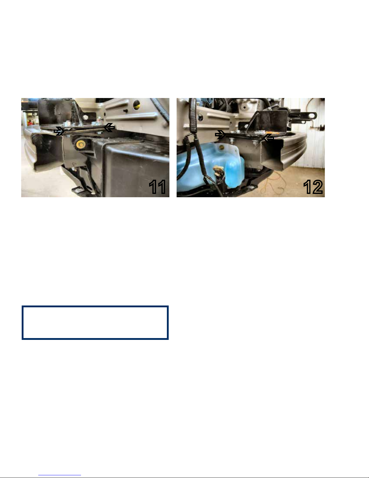
16. Slide metal bumper back on to the frame rail,
guiding the baseplate on top of frame rail. Align
with the existing holes of the bumper bracket.
Insert two 8MM-1.25 x 30MM hex bolts through
the baseplate into the two existing bumper bracket
holes using 8MM lock washers, and 3/8” at
washers (see arrow). Using a vice grip; clamp
the rear of the baseplate. Using the baseplate
as a template, drill into the frame rail through the
remaining baseplate holes (six). Three are found
on the top of the baseplate, another on the side
resting against the radiator support. Two more
are on the lower portion of the baseplate resting
against the side of frame rail. Do this to both sides
of the vehicle.

7. Using the 12MM socket, remove metric bolts
from the top and bottom of metal bumper and
set metal bumper aside to be reinstalled later.
Set baseplate in place with drilled holes. Insert
the 3/8”/14” nut plates into the frame end and
start the 3/8-16 x 1 1/2” hex bolts and the 3/8”
lock washers, do NOT tighten.
7
8. Slide the metal bumper between baseplate
and frame to align with existing holes. Use the
3/8” at washer between the metal bumper
and the baseplate to level as needed, vehicles
may vary. Tighten the 8MM-1.25 x 30MM hex
bolts, 8MM lock washers, and the 3/8” at
washers on the top side and existing bolts on
the bottom side. Do this to both sides of the
vehicle. BE SURE TO USE LOCTITE Red on
ALL bolts.
8
9. Tighten the bolts on the lower portion of the
baseplate and all installed bolts in the top of
the frame. Do this to both sides of the vehicle.
9
Page 5 of 7 292-6042 Rev. F 2/14/11
2003-05 Honda Pilot
Installation Instructions
BX2227
10. Align the nut plate with the drilled hole on the
back side of the radiator support and tighten
the 3/8-16 hex bolt and lock washer, as (white
arrow). Do this to both sides of the vehicle.
Using the 10MM socket, remove the metric
bolt from the air bafe, (grey arrow), and pull
the air bafe down away from the frame.
10

2003-05 Honda Pilot
Installation Instructions
BX2227
11. Place the backing plate on the bottom side of
the frame webbing to align with drilled holes,
insert the 3/8-16 x 1 1/2” hex bolts and 3/8” at
washers into this hole, tighten the 3/8-16 hex
nuts and 3/8” lock washers. Reinstall the air
bafe to its original position.
11
12. Place the backing plate on the bottom side of
the frame webbing to align with drilled holes,
insert the 3/8-16 x 1 1/2” hex bolts and 3/8” at
washer into this hole, tighten the 3/8-16 hex
nut and 3/8” lock washers.
12
13. Be sure ALL bolts on baseplate are tightened.
Reinstall the headlight assemblies and the
fascia, while assuring all electrical components
are properly plugged in.
Baseplate Installation is now Complete.
Install the tow bar and safety cables according
to the instructions included in their packages.
When demonstrating this to the customer, be
sure to include all of the Blue Ox packaging
and contents.
Do not substitute other devices if the tow bar
pin and clip are lost.
DEALER OR INSTALLER: BE CERTAIN
THE USER RECEIVES THE INSTRUCTION
SHEETS FOR THEIR PRODUCTS.
Be sure that ALL electrical connections
are plugged in properly and functioning
BEFORE Installing the fascia.
Page 6 of 7 292-6042 Rev. F 2/14/11

CUSTOMER SERVICE COMMITMENT
Blue Ox is committed to providing you with
exceptional customer care throughout your lifetime
with our products. Our team is here to assist you
with any questions you may have regarding the
performance of your product. Simply call 1-800-
228-9289 and you can speak with our customer
care team.
Additionally, please visit our website to see
which rallies our Destination America team will
be attending. For a nominal fee, our service
technician will service your towing system to
ensure it’s in proper working condition. Also as
a commitment to our customers, should you visit
our factory you can stay at our full service Blue
Ox campground at no charge along with enjoying
a factory tour.
Again thank you for being our customer and for
the condence you have shown in the performance
of our products. It is because of customers like
you we enjoy the success we have today.
© 2005, 08, 10, 11 Blue Ox
One Mill Road, Industrial Park
Pender, Nebraska 68047
Phone: (402) 385-3051
Toll Free: (888) 425-5382
Fax: (402) 385-3360
www.blueox.com
Page 7 of 7 292-6042 Rev. F 2/14/11
2003-05 Honda Pilot
Installation Instructions
BX2227
Shown without Removable Tabs Installed.
Shown with Removable Tabs Installed.
If the baseplate is in an accident, it must
be replaced. DO NOT use it again! An
accident can cause unseen damage and
using it again could result in more dam-
age or serious injury. DO NOT use the
baseplate if it is damaged or missing parts.

5/11/15
Permanent Baseplate Safety Cable Installation
Permanent baseplate safety cables are strongly recommended when towing a vehicle with a tow bar.
The principle function of the permanent baseplate safety cables is to prevent the towed vehicle from
breaking loose in the event the connection between the frame of the towed vehicle and the baseplate
fails or becomes disconnected. The cables must be connected from the baseplate to the frame rail
or cross member of the vehicle’s frame. The illustrations below show the possible arrangements
recommended by Blue Ox®. Each permanent baseplate safety cable must have an adequate weight
rating for the towing system. The weight rating of the two (2) cables together will not qualify.
Do not mount the permanent baseplate safety cables against wires, hoses or brake lines.
These permanent baseplate safety cables should remain installed as long as the baseplate is
installed on the vehicle. Permanent baseplate safety cables are to be used in conjunction with,
and NOT a replacement for legally required safety cables attaching the towed vehicle to the towing
vehicle.
Notice To Baseplate Installer
1. It is YOUR responsibility to watch for:
• Oil cooler and air conditioner lines
• Electrical wires and hoses
• Missing parts or attaching points on the frame
** If the baseplate is improperly installed and is against a wire or hose, it could cause uid leaks or
electrical shorts some time after the actual baseplate installation.
General Information
1. Ensure that your product(s) are registered online at www.blueox.com. It is crucial to register your product(s)
so that you may be alerted of product offerings, updates, upgrades, maintenance and safety bulletins, and/
or recalls.
2. It is the owner’s responsibility to inspect all towing equipment for cracked welds, missing or worn
parts and loose bolts before each towing trip. Be sure to use Loctite® Red on all bolts and tighten to the
recommended specications.
3. It is the owner’s responsibility to hook up all towing equipment per manufacturer’s instructions/
recommendations.
4. Remove the attachment tabs when not in use (if applicable).
Table of contents
Other Blue Ox Automobile Part manuals
Popular Automobile Part manuals by other brands

Edelbrock
Edelbrock ENDURASHINE 63-0299 installation instructions

Edelbrock
Edelbrock Performer RPM 60219 installation instructions

Edelbrock
Edelbrock 8192 installation instructions

Edelbrock
Edelbrock 72230 installation instructions

Edelbrock
Edelbrock 4100 Series installation instructions

Munters
Munters MWI Series Quick assembly guide