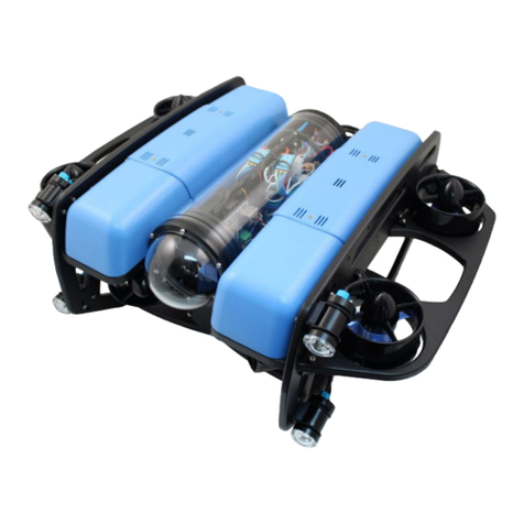
Blue Robotics BlueROV2 Manual

of#40#
1#
Assembly Intro
The BlueROV2 kit comes almost ready to dive. The assembly can be completed with basic
hand tools; no soldering or potting is required. We have included a couple of the tools to
make assembly and regular use as easy as possible.
Safety
When working with electricity, especially in water, always practice caution. Always
ensure that connections are secure and watertight. Keep your body away from spinning
motors and propellers.
When working with silicone grease and threadlocker, take care to minimize skin
contact. Wear protective nitrile or PVC gloves when handling.
Only apply threadlocker to screws contacting metal or the HDPE frame. Most
threadlockers are not chemically compatible with with polycarbonate, and will damage the
thrusters, fairings, and dome flange if used here. Refer to the documentation and chemical
compatibility notes of your threadlocker of choice for more information.
Required Tools (Not Included)
•#2 Phillips head screwdriver
•Wire cutters or scissors (for cutting zip ties)
•Medium-strength (blue) threadlocker such as Loctite 243
•Isopropyl alcohol or isopropyl alcohol wipes
•2 mm flat head screw driver
Assembling the Frame
Mounting the Battery Enclosure to the Bottom Panel
To mount the battery enclosure to the bottom panel, you will need the following parts and
tools:
•2 x Enclosure Clamp (3” Series)
•1 x Threadlocker
•1 x Bottom panel
•1 x Bag with four M4x14 socket head cap screws and four M3x12 socket head cap
screws
•1 x Watertight Enclosure for ROV/AUV (3” Series)
•1 x 3 mm hex key
•1 x 2.5 mm hex driver
1. Remove the Aluminium End Cap with 4 Holes (3” Series) to open the Watertight
Enclosure for ROV/AUV (3” Series) and set the bags inside of it to the side, except for
the bag with four M4x14 and four M3x12 screws in it.
2. Apply one drop of threadlocker to the bottom of each M4x14 socket head cap screw.
Roll the screws around on a paper towel to evenly spread the threadlocker and to
remove excess threadlocker.

of#40#
2#
3. Attach one of the Enclosure Clamps (3” Series) to the bottom panel using the four
M4x14 socket head cap screws. Be sure that the screw head is in the counterbore.
The bottom panel is only counterbored on one side. Tighten the screws until you can
feel them start to dig into the bottom panel.
4. Apply one drop of threadlocker to each of the 4 M3x12 screws. Roll the screws
around on a paper towel to evenly spread the threadlocker and to remove excess
threadlocker.
5. Place the Watertight Enclosure for ROV/AUV (3” Series) between the two Enclosure
Clamps (3” Series). The Enclosure Clamps have tapped holes on one side and
untapped holes on the other.
Ensure NO threadlocker comes into contact with the acrylic tube.
Install the four M3x12 screws into the Enclosure Clamps (3” Series) so that the screws
pass through the untapped holes on the first clamp and are secured into the tapped holes
on the alternate clamp. Install all four screws loosely at first and then slowly tighten them

of#40#
3#
on both sides evenly. Take care not to overtighten the screws. Keep the battery enclosure
approximately centered in the Enclosure Clamps (3” Series).
When you are finished tightening the screws, both sides should look similar to this:

of#40#
4#
Assembling the Center Panels
To assemble the center panels, you will need the following parts and tools:
•2 x Enclosure Cradle (4” Series)
•2 x Front center panels
•2 x Rear center panels
•1 x Threadlocker
•1 x Bag with eight M4x18 socket head cap screws
•1 x 3 mm hex key
1. Apply one drop of threadlocker to each of the eight M4x18 screws. Roll the screws
around on a paper towel to evenly spread the threadlocker and to remove excess
threadlocker.
2. Attach one of the Enclosure Cradle (4” Series) to the rear center panels. Tighten the
screws until they indent the rear center panels slightly.
3. Attach the other Enclosure Cradle (4” Series) to the front center panels. Tighten the
screws until they indent the front center panels slightly.

of#40#
5#
Assembling the Frame
To assemble the frame, you will need the following parts and tools:
•1 x Threadlocker
•1 x Bag with 12 M5x16 button head cap screws
•2 x Side panels
•1 x Bottom panel with the Watertight Enclosure for ROV/AUV (3” Series) installed
•1 x Front center panel assembly
•1 x Rear center panel assembly
•1 x 3 mm hex key
1. Apply one drop of threadlocker to each of the 12 M5x16 screws. Roll the screws
around on a paper towel to evenly spread the threadlocker and to remove excess
threadlocker.
2. Install both side panels to the bottom panel using four of the M5x16 screws; the
Aluminium End Cap (3” Series) on the Watertight Enclosure for ROV/AUV (3” Series)
should be on the same side as the Lumen mounting holes. It is very important to
avoid overtightening these screws. Tighten these screws using the provided 3 mm
hex key. Hold the short end of the 3 mm hex key while you are tightening the M5x16
screws. Do not tighten beyond the tightness you can achieve holding the short end of
the 3 mm hex key.

of#40#
6#
3. Install the center panel assemblies to the side panels using the remaining eight M5x16
screws. It is very important to avoid overtightening these screws. Tighten these
screws using the provided 3 mm hex key. Hold the short end of the 3 mm hex key
while you are tightening the M5x16 screws. Do not tighten beyond the tightness you
can achieve holding the short end of the 3 mm hex key.
Now the BlueROV2 should look like the picture below:

of#40#
7#

of#40#
8#
Electronics Enclosure Overview
The images below show orientation of the main pieces of hardware in the electronics
enclosure. They also point out the names of several of the important parts for assembly
that will be discussed in the remaining instructions.
Top View
Starboard View
Port View

of#40#
9#
Front View
Connection diagrams
These diagrams outline all of the electrical connections between components in the ROV.
There is a different diagram for each version of the ROV that Blue Robotics has produced.
•BlueROV2 with red-wire (BEC) ESCs (Pre-2018)
•BlueROV2 with no-red-wire ESCs (2018 and later)
•BlueROV2 Heavy

of#40#
10#
Installing the Cables
Removing the Electronics Enclosure Endcap
The endcap will need to be removed from the electronics enclosure in order to install the
cable penetrators. To remove the endcap, you will need the following parts and tools:
•1 x Large flat head screw driver (Optional)
•1 x The electronics enclosure assembly
•1 x 2.5 mm key driver
1. Remove the Watertight Enclosure for ROV/AUV with Dome End Cap installed from the
rear O-Ring Flange (4” Series). If this step is difficult, you can place a large flat head
screwdriver into the slots on the O-Ring Flange (4” Series), and then twist to get a gap
between the acrylic tube and the O-Ring Flange (4” Series). Once you have the gap,
you can wedge a screw driver between the end of the acrylic tube and the O-Ring
Flange (4” Series) to finish removing the acrylic tube.
2. Remove the Aluminium End Cap with 14 Holes by removing the six M3x12 screws
using the M2.5 hex driver. Place the M3x12 screws, clips (small L-shaped parts), and
face seal O-ring in a safe place.

of#40#
11#
Installing the Penetrators
To install the Penetrators, you will need the following parts and tools:
•1 x Cable Penetrator Nut (Black for Standard Tether/Red for Slim Tether), and O-ring
from one end of the Tether
•6 x Cable Penetrator Nut (red), and O-ring from bag inside each Thruster tube
packages
•(Optional if no Lumens) 1 x Cable Penetrator Nut (red) and O-ring from spares bag
•1 x Silicone Grease - 10g Tube
•1 x Aluminium End Cap with 14 Holes w/ 3 Cable Penetrator Blanks, 1 Bar30 Pressure
Sensor, 1 Enclosure Vent and Plug, and 1 power cable installed
•3 x T200 with counter-clockwise thrusters
•3 x T200 with clockwise thrusters
•1 x Set of Lumen lights (optional)
•1 x Fathom ROV Tether
•1 x Penetrator Wrench
The Aluminium End Cap with 14 Holes comes with 3 Cable Penetrator Blanks, 1 Bar30
Pressure Sensor, 1 Enclosure Vent and Plug, and 1 power cable installed.

of#40#
12#

of#40#
13#
If you install the remaining penetrators as shown in the diagram below, it will keep
everything neat and organized.
1. Remove eight of the O-rings and apply silicone grease to them. Keep the other O-ring
in the bag, you will need it in a minute.
2. Wipe the exterior surface of the electronics enclosure endcap clean with isopropyl
alcohol or isopropyl alcohol wipes, and make sure it is free of any particles in the
areas where the penetrator O-rings will sit.
3. Install the O-rings onto all of the thruster penetrators, the lumen penetrator, and the
tether penetrator.
4. Install the penetrators to the end cap in the order shown below. Tighten to finger tight,

of#40#
14#
then use the provided wrench to tighten them an additional ~1/16 of a turn. If you
can’t loosen them with your fingers, they are tight enough.
1. Thruster 1 (CCW propeller) with red penetrator nut
2. Thruster 5 (CCW propeller) with red penetrator nut
3. Thruster 3 (CW propeller) with red penetrator nut
4. Lumen with red penetrator nut (or Blank Penetrator (red) if not installing Lumens)
5. Thruster 4 (CW propeller) with red penetrator nut
6. Thruster 6 (CW propeller) with red penetrator nut
7. Thruster 2 (CCW propeller) with red penetrator nut
8. Tether with black penetrator nut (standard Tether) or red penetrator nut (Slim
Tether)
Installing the End Cap
To reinstall the Aluminium End Cap with 14 Holes, you will need the following parts and
tools:
•The face seal O-ring, the 6 M3x12 screws, and the clips that you removed from the
end cap earlier
•1 x Silicone Grease - 10g Tube
•1 x Aluminium End Cap with 14 Holes with all Cable Penetrators and Blank
Penetrators installed
•1 x 2.5 mm hex driver
1. Clean the O-ring and make sure that it is free of any debris or damage.
2. Clean the O-Ring Flange (4” Series) and make sure that the O-ring groove is free of
any debris or damage
3. Apply Silicone grease to the O-ring.
4. Install face seal O-ring onto the O-Ring Flange (4” Series).
5. Apply one drop of threadlocker to each of the M3x12 screws. Roll the screws around
on a paper towel to evenly spread the threadlocker and to remove excess
threadlocker.
6. Install Aluminium End Cap with 14 Holes with all Cable Penetrators and Blank
Penetrators installed onto the O-Ring Flange (4” Series). Do not fully tighten any
screws when first installing them; it may cause the O-ring to slip out of its groove. The
end cap’s orientation when installed should match the image below. Make sure that
the clips are oriented correctly. One should be just right of the Thruster 3 penetrator,
and the other should be just left of the Thruster 4 penetrator.

of#40#
15#
Finishing the Battery Enclosure
To complete the assembly of the battery enclosure, you need the following parts and
tools:
•1 x Bag labelled “Extra Blank Penetrators [2]”
•1 x Silicone Grease - 10g Tube
•1 x End Cap with 4 Holes (3” Series)
•1 x Penetrator wrench
•1 x XT90 to 3.5 mm bullet connector adapter
•1 x 1.5 inch piece of heat shrink
•1 x Heat gun, hairdryer, or lighter
1. Apply silicone grease to the O-ring.
2. Install the O-ring onto the battery power cable penetrator.
3. Install the battery power cable penetrator into the opening in the battery end cap.
4. Install one Cable Penetrator Nut (Red) on to the battery power cable penetrator and
tighten with penetrator wrench.
5. Place the 1.5 inch long piece of black heat shrink over the end of the battery power
cable penetrator.
6. Apply heat to the heat shrink using your heat gun, hairdryer, or lighter until the heat
shrink is firmly attached to the penetrator and snug to the two wires. You should be
able to see the threads in the penetrator through the heat shrink.

of#40#
16#
7. Install the XT90 to bullet connector adapter to the battery power wire.
8. If you wish to do the Optional Preliminary Vacuum Test, remove the Vent Plug from the
Vent Penetrator Bolt and install the endcap onto the battery enclosure. You will also
need to remove the Vent Plug for the Vent Penetrator Bolt on the electronics
enclosure.

of#40#
17#
Optional (recommended) Preliminary Vacuum Test
This point is the best time in the assembly process to perform a vacuum test. Since you
have installed all of the penetrators, but have not done any of the wiring, troubleshooting
will be as easy as possible. You will need to use the vacuum pump that comes with the kit.
1. Install the Watertight Enclosure (4” Series) with installed Dome onto the O-Ring Flange
(4” Series) that is attached to the Aluminium End Cap with 14 Holes (4” Series)
2. Assemble the vacuum tee.
Now you are ready to perform the preliminary vacuum test.

of#40#
18#
1. Test your vacuum pump to ensure that it is not leaking. See our Testing the Test
Setup Tutorial for detailed instructions.
2. Insert one of the vacuum plugs into the battery enclosure vent penetrator.
3. Insert the other vacuum plug into the electronics enclosure vent penetrator.
4. Pump the vacuum until the gauge reads 10 in. Hg [34 kPa] vacuum. If you cannot pull
a vacuum, try the suggestions following step 6, below.

of#40#
19#
5. Let the BlueROV2 and pump sit for 15 minutes.
6. If the gauge reads above 9 in. Hg [31 kPa] after 15 minutes, your seals are acceptable.
If the gauge reads below 9 in. Hg [31 kPa] vacuum after 15 minutes, you should check the
following:
1. Make sure that the M3 screws on the front and back end caps of the battery and
electronics enclosure using the M2.5 hex driver. If you are able to tighten one or more,
attempt the vacuum test again.
2. Make sure that the penetrators on the battery and electronics enclosure are fully

of#40#
20#
tightened. Check by attempting to loosen by hand. If you are able to loosen one or
more, tighten them then attempt the vacuum test again.
3. Make sure that all of the O-rings are installed in the penetrators. If any are missing,
install then attempt the vacuum test again.
4. Check that the face seal O-rings and radial O-rings are installed in the battery and
electronics enclosures and in good condition. If you find a damaged or missing O-ring,
install and attempt the vacuum test again.
If you are still having trouble holding vacuum, please contact us
To continue assembling the BlueROV2, remove the acrylic tube and dome from the
electronics enclosure.
Installing the Power Wires from the Penetrators
To install the wires from the penetrators, you will need the following parts and tools:
•1 x Large (~#2) Phillips head screw driver
1. Connect the battery power bullet connectors to bullet connectors on XT60 to bullet
connector adapter.
2. Connect the Lumen power wire (red) to the Power Terminal Block with the other red
wires. Use the rear screw terminal that is second from the bottom. To help keep the
Other manuals for BlueROV2
2
Table of contents
Other Blue Robotics Robotics manuals
