Blue Sky Energy GREENROCK Home Installation and operation manual
Fornacher Strasse 12 Telephone +43 (720) 010 188
A-4870 Vöcklamarkt Email: office@bluesky-energy.eu
Austria www.bluesky-energy.eu
January 10, 2020/greenrock-heimspeicher_installations- & inbetriebnahmehandbuch_v02_en 1
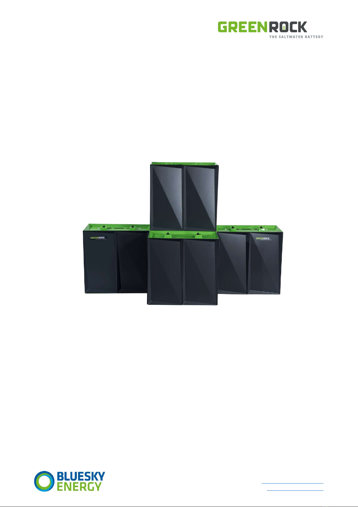
GREENROCK HOME
ENERGY STORAGE
INSTALLATION & STARTUP MANUAL

Fornacher Strasse 12 Telephone +43 (720) 010 188
A-4870 Vöcklamarkt Email: office@bluesky-energy.eu
Austria www.bluesky-energy.eu
January 10, 2020/greenrock-heimspeicher_installations- & inbetriebnahmehandbuch_v02_en 2
TABLE OF CONTENTS
Introduction .............................................................................................................................................................................................5
Explanation safety instructions ...............................................................................................................................................................5
Contact information ................................................................................................................................................................................5
(1) Safety regulations ..........................................................................................................................................................................6
1.1 General aspects ....................................................................................................................................................................6
1.2 Ambient conditions ..............................................................................................................................................................6
1.3 Qualified staff .......................................................................................................................................................................7
1.4 EMC measures ......................................................................................................................................................................7
1.5 Data safety ...........................................................................................................................................................................7
1.6 Copyright ..............................................................................................................................................................................7
1.7 Scope of application .............................................................................................................................................................7
(2) Safety instructions .........................................................................................................................................................................8
2.1 Electrical hazards..................................................................................................................................................................8
2.2 Chemical hazards .................................................................................................................................................................8
2.3 Thermal hazards ...................................................................................................................................................................9
2.4 Physical hazards ...................................................................................................................................................................9
(3) Product description......................................................................................................................................................................10
3.1 Intended use ......................................................................................................................................................................10
3.2 Type plate ...........................................................................................................................................................................10
3.2.1 Symbols type plate and system .....................................................................................................................................10
(4) Conditions at installation site ......................................................................................................................................................11
4.1 Size and weight ..................................................................................................................................................................11
4.2 Ventilation ..........................................................................................................................................................................11
4.3 Humidity .............................................................................................................................................................................11
4.4 Ambient temperature ........................................................................................................................................................11
4.5 Space required ...................................................................................................................................................................11
(5) Installation of GREENROCK Home Energy Storage system ..........................................................................................................12
5.1 Unpacking ..........................................................................................................................................................................12
5.2 Transport ............................................................................................................................................................................12
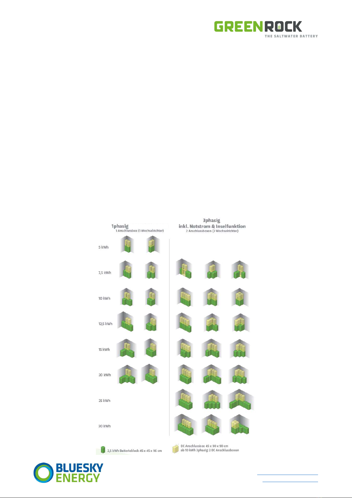
5.3 Installation variants ............................................................................................................................................................12
5.4 Structure of GREENROCK single phase ...............................................................................................................................13
5.5 Structure of GREENROCK three phase ...............................................................................................................................15
5.6 Cladding batteries - What to consider ................................................................................................................................17
5.7 Tilt protection.....................................................................................................................................................................17
5.8 Wall mount .........................................................................................................................................................................17
(6) GREENROCK Home Energy Storage - system components ..........................................................................................................18
6.1 Power inverter ...................................................................................................................................................................18
6.2 GREENROCK Energy Management System (EMS) ..............................................................................................................18
6.3 GREENROCK controller .......................................................................................................................................................18

Fornacher Strasse 12 Telephone +43 (720) 010 188
A-4870 Vöcklamarkt Email: office@bluesky-energy.eu
Austria www.bluesky-energy.eu
January 10, 2020/greenrock-heimspeicher_installations- & inbetriebnahmehandbuch_v02_en 3
6.4 Combiner Board (DC distribution) ......................................................................................................................................18
6.5 Terminal .............................................................................................................................................................................18
6.6 Battery stacks .....................................................................................................................................................................18
(7) Electrical installation ....................................................................................................................................................................19
7.1 Connection of the battery stacks .......................................................................................................................................20
7.1.1 Opening the cover of the Combiner Board ...................................................................................................................20
7.1.2 Connection of Combiner Board .....................................................................................................................................21
7.1.3 Laying the battery cables and connecting them to the battery stacks ..........................................................................22
7.1.4 Ambient temperature sensor ........................................................................................................................................22
7.2 Internal cabling ..................................................................................................................................................................23
7.2.1 Internal cabling - single-phase system...........................................................................................................................23
7.2.2 Internal cabling - three-phase system ...........................................................................................................................23
7.3 Connection to the mains supply .........................................................................................................................................25
7.3.1 Connection - single-phase system .................................................................................................................................25
7.3.2 External cabling - three-phase system ..........................................................................................................................25
7.3.3 External cabling - DC coupling (optional) ......................................................................................................................26
7.3.4 Communication connection DC coupling to MPPT charge controller ...........................................................................26
7.4 Installation of energy meter ...............................................................................................................................................27
7.4.1 Carlo Gavazzi Type EM340 direct measuring energy meter ..........................................................................................27
7.4.2 Carlo Gavazzi Type EM330 indirect measuring meter ...................................................................................................27
7.4.3 Communicative integration of the energy meters ........................................................................................................28
7.4.4 Connecting the energy meters – communication .........................................................................................................29
7.5 Installation of GREENROCK router .....................................................................................................................................30
7.5.1 Connection of network cable ........................................................................................................................................30
7.5.2 Power supply connection and router placement ..........................................................................................................31
7.5.3 Settings of GREENROCK router ......................................................................................................................................31
7.5.4 WLAN access .................................................................................................................................................................31
7.5.5 Installation without GREENROCK router .......................................................................................................................31
(8) Switching the home energy storage on and off ...........................................................................................................................32
8.1 Switching on the system ....................................................................................................................................................32
8.2 Switching off the system ....................................................................................................................................................33
(9) Access to GREENROCK EMS web interface ..................................................................................................................................34
9.1 Using GREENROCK router...................................................................................................................................................34
9.2 Using customer network ....................................................................................................................................................34
9.3 Using GREENROCK Cloud ...................................................................................................................................................35
(10) PV DC coupling with Victron Smartsolar ..................................................................................................................................36
10.1 Installation .........................................................................................................................................................................36
10.2 DC coupling and additional protection of the MPPT charge controller..............................................................................36
(11) Other information ....................................................................................................................................................................38
11.1 Frequently asked questions during setup ..........................................................................................................................38
11.2 Emergency power operation ..............................................................................................................................................38

Fornacher Strasse 12 Telephone +43 (720) 010 188
A-4870 Vöcklamarkt Email: office@bluesky-energy.eu
Austria www.bluesky-energy.eu
January 10, 2020/greenrock-heimspeicher_installations- & inbetriebnahmehandbuch_v02_en 4
11.3 Power inverter ...................................................................................................................................................................38
11.4 Storage ...............................................................................................................................................................................38
11.5 Maintenance ......................................................................................................................................................................38
11.6 Disposal ..............................................................................................................................................................................38
(12) Enclosures ................................................................................................................................................................................39
12.1 Enclosure (A) - Cabling diagram, system internal cabling ..................................................................................................40
12.2 Enclosure (B) - TN emergency power network ...................................................................................................................41
12.3 Enclosure (C) - TN network with stand-alone AC PV ..........................................................................................................42
12.4 Enclosure (D) - TN network with stand-alone 2 AC PV .......................................................................................................43
12.5 Enclosure (E) - TN network with stand-alone DC PV ..........................................................................................................44
12.6 Enclosure (F) - TN network with stand-alone 2 AC PV + DC PV ..........................................................................................45
12.7 Enclosure (G) - TN network with complete stand-along DC + AC PV ..................................................................................46
12.8 Enclosure (H) - TN network including WP ..........................................................................................................................47
(13) Glossary ....................................................................................................................................................................................48
Fornacher Strasse 12 Telephone +43 (720) 010 188
A-4870 Vöcklamarkt Email: office@bluesky-energy.eu
Austria www.bluesky-energy.eu
January 10, 2020/greenrock-heimspeicher_installations- & inbetriebnahmehandbuch_v02_en 5
© 2019 BlueSky Energy
All information in this document is subject to regular updates and modifications. In the course of updates and changes to
GREENROCK products, BlueSky Energy will create new drawings and/or related documentation to replace those in this document.
We reserve the right to make changes and technical improvements without prior notice.
For the latest documents, please contact us at [email protected]
All information in this user manual has been compiled and checked with the greatest care. Nevertheless, errors cannot be
completely ruled out. The company BlueSky Energy GmbH can therefore assume no liability for errors and resulting consequences.
INTRODUCTION
We thank you for your trust and congratulate you on your technically high-quality GREENROCK product. This document will help
you to familiarize yourself with it. By reading this document carefully, you will get to know the various possibilities of your
GREENROCK product. That is the only way you can make the best possible use of its advantages.
This document is intended to provide technical information and safety instructions for the GREENROCK product concerned. Keep
this document in a safe place near the GREENROCK product and pass it on to other operators if necessary. Only pass on
GREENROCK products to third parties with complete documentation.
The following basic safety instructions must always be observed when using the GREENROCK product. Carefully read the following
safety instructions and information on safe operation of the GREENROCK product.
EXPLANATION SAFETY INSTRUCTIONS
HAZARD
Note on danger to life if ignored
WARNING
Note on possible serious injury or danger to life if ignored
CAUTION
Note on possible slight risk of injury or damage to property if ignored
DEPENDING ON THE DEGREE OF DANGER
Note on hazards due to electric current
IMPORTANT
An important functional note
NOTE
General information or special tips
If you see one of the symbols shown in the following chapters, increased attention is required.
CONTACT INFORMATION
BlueSky Energy
Fornacher Strasse 12
A-4870 Vöcklamarkt
Austria www.bluesky-energy.eu
Fornacher Strasse 12 Telephone +43 (720) 010 188
A-4870 Vöcklamarkt Email: office@bluesky-energy.eu
Austria www.bluesky-energy.eu
January 10, 2020/greenrock-heimspeicher_installations- & inbetriebnahmehandbuch_v02_en 6
(1) SAFETY REGULATIONS
1.1 General aspects
The product has been manufactured in accordance with the state of the art and recognised safety regulations. Nevertheless, in the
event of faulty operation or misuse, there is a danger to
life and limb of the operator or third parties
the device and other material assets of the operator
the efficient work with the device
All persons involved in the commissioning, servicing and maintenance of the product must
be qualified correspondingly
have knowledge in dealing with electrical installations, and
read this manual completely and follow it exactly
The documentation must always be kept at the place of use of the product. In addition to the documentation, the generally
applicable and local regulations on accident prevention and environmental protection must be observed.
All safety and hazard information on the product
must be kept in legible condition
must be undamaged
must not be removed
must not be covered, pasted over or painted over
The terminals can reach high temperatures.
Only operate the product if all protective devices are fully functional. If the protective devices are not fully functional, there is a
danger to
life and limb of the operator or third parties
the device and other material assets of the operator
the efficient work of the product
Before switching on the product, have any safety devices that are not fully functional repaired by an authorised specialist company.
Never bypass or shut down protective devices.
Before switching on the product, eliminate any faults that could impair safety.
Your safety is all-important!
1.2 Ambient conditions
Operation or storage of the product outside the specified range is considered improper. The manufacturer is not liable for any
damage resulting from this.
For detailed information about the permissible ambient conditions, please refer to the technical data of your GREENROCK product.

Fornacher Strasse 12 Telephone +43 (720) 010 188
A-4870 Vöcklamarkt Email: office@bluesky-energy.eu
Austria www.bluesky-energy.eu
January 10, 2020/greenrock-heimspeicher_installations- & inbetriebnahmehandbuch_v02_en 7
1.3 Qualified staff
The information in this document is intended for qualified staff only. An electric shock can be fatal. Do not perform any activities
other than those described in the documentation. This shall also apply if you are qualified to do so.
All cables and wires must be solid, undamaged, insulated and sufficiently dimensioned. Loose connections, braised, damaged or
undersized cables and lines should be repaired immediately by an authorised specialist company.
Maintenance and repair may only be carried out by an authorised specialist company.
It cannot be guaranteed that externally procured parts have been designed and manufactured in a way that meets the
requirements of stress and safety. Only use original spare parts (also applies to standard parts).
Do not make any changes, installations or conversions to the product without the manufacturer's approval.
If the components are not in perfect condition, replace them immediately.
1.4 EMC measures
In special cases, despite compliance with the standardized emission limit values, influences for the intended area of application
may occur (e.g. if sensitive devices are at the installation site or if the installation site is in the vicinity of radio or television
receivers). In this case, the operator is obligated to take appropriate measures to remedy the fault.
1.5 Data safety
The user is responsible for saving changes to the factory settings. The manufacturer is not liable for deleted personal settings.
1.6 Copyright
The copyright to this documentation remains with the manufacturer.
The information contained in these documents is the property of BlueSky Energy GmbH. Publication, in whole or in part, requires
the written consent of BlueSky Energy GmbH. Any internal duplication intended for evaluation of the product or for proper use is
permitted and does not require approval.
Text and illustrations correspond to the state of the art at the time of publication. Subject to change without notice. The content of
the documentation does not justify any claims on the part of the buyer. We are grateful for any suggestions for improvement and
for any errors in the documentation.
Operating instructions, manuals and software are protected by copyright. Copying, duplicating, translating, translating into any
electronic medium or into machine-readable form in whole or in part is only permitted with the express permission of BlueSky
Energy GmbH. An exception applies to the making of a backup copy of software for one's own use for backup purposes. Violations
will be prosecuted under criminal law and will result in damages. All trademarks or brands used in this document refer only to the
respective product or the owner of the trademark or brand. The naming of products which are not from BlueSky Energy GmbH is
exclusively for information purposes. BlueSky Energy GmbH makes no claim to trademarks or brands other than its own.
1.7 Scope of application
This document applies to the GREENROCK Home Energy Storage Multigrid.

Fornacher Strasse 12 Telephone +43 (720) 010 188
A-4870 Vöcklamarkt Email: office@bluesky-energy.eu
Austria www.bluesky-energy.eu
January 10, 2020/greenrock-heimspeicher_installations- & inbetriebnahmehandbuch_v02_en 8
(2) SAFETY INSTRUCTIONS
2.1 Electrical hazards
WARNING
The GREENROCK Energy Storage system works with voltages of up to 400 V at correspondingly high currents.
Since currents of 250 mA or more can be lethal, appropriate precautions must be taken.
Measures
In case of danger, immediately disconnect the energy storage from the power supply.
The covers of the GREENROCK energy storage may only be removed by trained specialist staff.
Do not touch any live parts.
WARNING
The metallic connections of the Combiner Board (DC distribution) of the GREENROCK accumulator are under power.
When working on or in the accumulator, appropriate precautions must be taken.
Measures
Disconnect the energy storage from the power supply.
Open the fused circuit-breaker to disconnect the batteries from the Combiner Board.
Use insulated tools only.
CAUTION
The poles of the battery stacks of the GREENROCK energy storage are always live; appropriate precautions are
necessary.
Measures
Do not place any tools or other material on the battery stacks.
Use insulated tools only when working on the energy storage unit.
2.2 Chemical hazards
NOTE
The materials used in the GREENROCK Energy Storage systems are non-toxic. The electrolyte is a pH-neutral salt
water based on sodium sulphate.
Measures
If you come into contact with the electrolyte, wash the affected areas thoroughly with water.
Electrolyte residues on the battery or in the vicinity of the battery can simply be wiped away with a cloth.
A drip tray under the battery stacks is not required.
Fornacher Strasse 12 Telephone +43 (720) 010 188
A-4870 Vöcklamarkt Email: office@bluesky-energy.eu
Austria www.bluesky-energy.eu
January 10, 2020/greenrock-heimspeicher_installations- & inbetriebnahmehandbuch_v02_en 9
WARNING
The GREENROCK energy storage can release traces of gases during operation:
H2, O2, CO2, CO. To stop these gases collecting, appropriate measures are required.
Measures
A natural ventilation of 0.5 m3/h per installed kWh is recommended.
If the natural ventilation of the installation site is not sufficient, appropriate technical ventilation must be
provided.
2.3 Thermal hazards
WARNING
Risk of injury due to hot Combiner Board! The Combiner Board inside the energy storage could become very hot, so
appropriate measures are necessary.
Measures
Do not touch Combiner Board.
WARNING
Fire hazard through covered openings and gaps! The GREENROCK energy storage can become very hot during
operation. The openings and gaps of the energy storage are deliberately designed!
Measures
The energy storage must not be used as a shelf!
The openings and gaps of the energy storage must not be covered!
2.4 Physical hazards
WARNING
Risk of injury and/or material damage due to heavy battery stacks. The battery stacks of the GREENROCK energy
storage weigh 140 kg. Appropriate measures are necessary to avoid injuries.
Measures
When transporting and setting up the energy storage, appropriate aids must be used to ensure safe working
(safety shoes/gloves/hand pallet truck/sack truck/crane).
WARNING
Risk of injury or death and/or damage to property due to overturning of the energy storage. The GREENROCK
energy storage is high and heavy. Appropriate measures are necessary to prevent the energy storage from tipping
over or falling over.
Measures
The energy storage must be fixed to a wall with material suitable for the masonry.

Fornacher Strasse 12 Telephone +43 (720) 010 188
A-4870 Vöcklamarkt Email: office@bluesky-energy.eu
Austria www.bluesky-energy.eu
January 10, 2020/greenrock-heimspeicher_installations- & inbetriebnahmehandbuch_v02_en 10
(3) PRODUCT DESCRIPTION
The GREENROCK Home Energy Storage system is a modular power storage system consisting of saltwater batteries, hereinafter
referred to as battery stacks, Victron Energy inverters, a GREENROCK energy management system and a DC junction box with
battery fuses.
The system is perfectly suitable for increasing the self-consumption of photovoltaic systems. Depending on the system and design,
the PV system can be AC- or DC-coupled.
Depending on the version, the GREENROCK Home Energy Storage system is an emergency power & stand-alone unit and is
available in single-phase and three-phase versions.
3.1 Intended use
The product is not splash-proof. The product is only suitable for indoor use. Use the product only in accordance with the
information in the enclosed documentation and in accordance with local standards and guidelines. Any other use may result in
personal injury or damage to property. For safety reasons, it is prohibited to modify the product or install components that are not
expressly recommended or sold for the product by BlueSky Energy. Unauthorized modifications or conversions invalidate the
warranty claims and the operating permit. Any use of the product other than that described in its intended use shall be considered
as improper use. The enclosed documentation is an integral part of the product. The documentation must be read, observed and
kept accessible at all times.
3.2 Type plate
The type plate with the exact device designation unambiguously identifies the product. It is located on the cover of the Combiner
Board inside the system. An additional identical type plate is supplied with the device, which is to be attached to the cover part
with the internal cabling. This cover part must be placed on the main junction box in front of the inverter.
The type plate must be permanent, legible and affixed to the outside of the product and must not be removed.
3.2.1 Symbols type plate and system
Symbol Meaning Explanation
CE label The device complies with the requirements of the
applicable EU directives and standards.
Warning of hot surface Risk of injury due to hot Combiner Board! The
Combiner Board inside the energy storage could
become very hot.
Danger to life due to high electrical voltages in the
power storage system!
Even after disconnecting the device from external
voltage, voltage may still be present in the device.
Risk of injury and/or material damage due to heavy
battery stacks.
The battery stacks of the GREENROCK Energy
Storage weigh 140 kg. Appropriate measures are
necessary to avoid injuries.
Install the storage system indoors or away from weather
conditions.
A completely enclosed area is not required.
Waste Electrical and Electronic Equipment (WEEE) The components of the system must not be disposed
of with household waste but must be sent to a
specialist company for recycling.
Return to the recycling cycle.
Observe documentation. The documentation supplied with the system
contains safety instructions.

Fornacher Strasse 12 Telephone +43 (720) 010 188
A-4870 Vöcklamarkt Email: office@bluesky-energy.eu
Austria www.bluesky-energy.eu
January 10, 2020/greenrock-heimspeicher_installations- & inbetriebnahmehandbuch_v02_en 11
(4) CONDITIONS AT INSTALLATION SITE
The energy storage system should be installed indoors or protected from weather conditions. A completely enclosed area is not
required.
Do not install or operate the energy storage system in direct sunlight.
4.1 Size and weight
Exact size and weight specifications can be found in the data sheet. The installation site must be suitable for the size and weight of
the energy storage.
4.2 Ventilation
GREENROCK energy storage emits traces of gases during normal operation. A natural and continuous ventilation of 0.5 m3/h per
installed kWh is recommended. If the natural ventilation of the installation site is not sufficient, appropriate technical ventilation
must be provided. Alternatively, it is recommended that ventilation be installed in accordance with local battery room guidelines. In
Europe and other locations, the EN 50272 guidelines recommend the installation of batteries in well ventilated rooms where the
ventilation corresponds to the battery capacity and the exhaust air is exhausted outside the building.
4.3 Humidity
Install the energy storage system in a clean and tidy environment protected from water ingress. A direct supply of water to the
energy storage can lead to short circuits.
4.4 Ambient temperature
The GREENROCK Home Energy Storage system is designed for temperatures from -5 °C to +40 °C (outside this temperature range
there is the possibility of a power reduction of the system).
The battery storage must be operated at an ambient temperature of between -5 °C and +50 °C on a 24-hour average basis.
Operation outside these limits may reduce the life of the storage or cause irreparable damage.
The energy storage must be stored within the following temperatures: -5 °C to +50 °C. Storage outside these limits may cause
permanent damage to the battery.
4.5 Space required
Depending on the selected system size, a different space requirement of the system is required. This must be provided in
accordance with the data sheet.
The system must be placed at a distance of 10 cm from the wall due to internally installed fans.
Fornacher Strasse 12 Telephone +43 (720) 010 188
A-4870 Vöcklamarkt Email: office@bluesky-energy.eu
Austria www.bluesky-energy.eu
January 10, 2020/greenrock-heimspeicher_installations- & inbetriebnahmehandbuch_v02_en 12
(5) INSTALLATION OF GREENROCK HOME ENERGY STORAGE
SYSTEM
5.1 Unpacking
On receipt of the delivery, check that the tilt and shock indicator has not tripped (if fitted) and that the packaging and boxes have
not been punctured or broken.
Unpack the individual components carefully and check the completeness of the scope of delivery, and also check whether
electrolyte has leaked or whether connections are damaged or missing.
If you notice any damage or missing components, please contact your distributor or sales partner immediately. Please also include
photos in your documentation of the damage.
5.2 Transport
Use suitable equipment to move and transport the battery stacks. The stacks can be transported with an appropriately designed
pallet truck. Position the product so that the cabling is not damaged.
During transport, make sure that the battery stacks are not tilted more than 45 degrees!
5.3 Installation variants
GREENROCK Energy Storage systems are always mounted on the wall, in a corner.
Fornacher Strasse 12 Telephone +43 (720) 010 188
A-4870 Vöcklamarkt Email: office@bluesky-energy.eu
Austria www.bluesky-energy.eu
January 10, 2020/greenrock-heimspeicher_installations- & inbetriebnahmehandbuch_v02_en 13
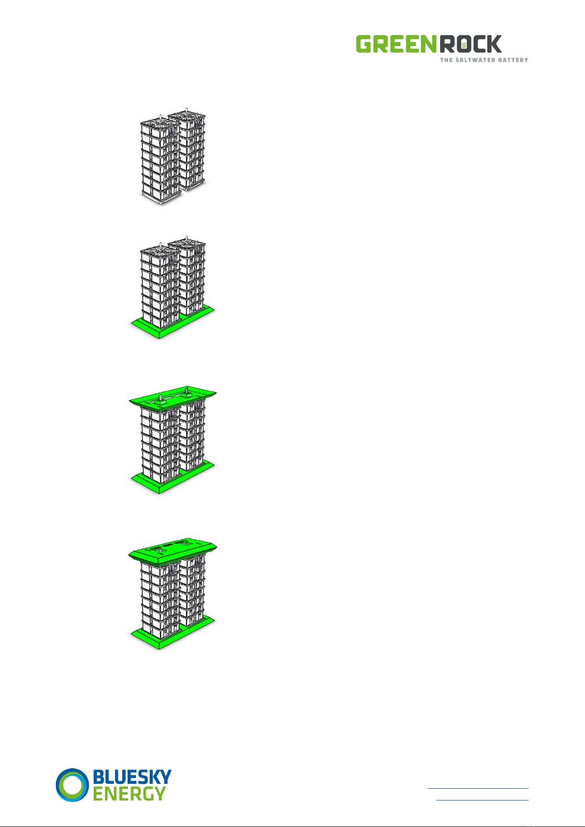
5.4 Structure of GREENROCK single phase
Place the battery stacks at their destination and align
them roughly.
The cabling of the batteries must be on the front side.
Use appropriate lifting aids for this purpose.
The distance from threaded bolt to threaded bolt is
400 mm (central).
If the battery casing option was selected:
(without which you can skip this step)
Slip over the eyeglass-shaped base plate, which
serves as a rough positioning template.
The Velcro fasteners must point outwards and
upwards.
Be careful not to damage the cabling.
Place the base plate/intermediate plate on the two
battery stacks.
The cabling openings must be on the rear side.
Next, place and centre the base/intermediate plate of
the junction box.
The cabling openings must again be on the rear side.

Fornacher Strasse 12 Telephone +43 (720) 010 188
A-4870 Vöcklamarkt Email: office@bluesky-energy.eu
Austria www.bluesky-energy.eu
January 10, 2020/greenrock-heimspeicher_installations- & inbetriebnahmehandbuch_v02_en 14
Place the junction box on the base plate.
Make sure that the cover is mounted on the inverter
frame.
The Velcro fasteners of the lid cover must point
outwards and down.
Centre the junction box so that the spacer bolts
engage in the holes of the cross brace of the box.
Make sure that the junction box is firmly fixed.
Fasten the junction box with the enclosed M16
screws with a maximum torque of 30 Nm.
Optionally it is also possible to fix the junction box to
a wall using a wall mounting set.
The cladding parts are attached by means of the pre-
assembled Velcro points.
Cladding of the battery stacks: OPTIONAL.
Fornacher Strasse 12 Telephone +43 (720) 010 188
A-4870 Vöcklamarkt Email: office@bluesky-energy.eu
Austria www.bluesky-energy.eu
January 10, 2020/greenrock-heimspeicher_installations- & inbetriebnahmehandbuch_v02_en 15
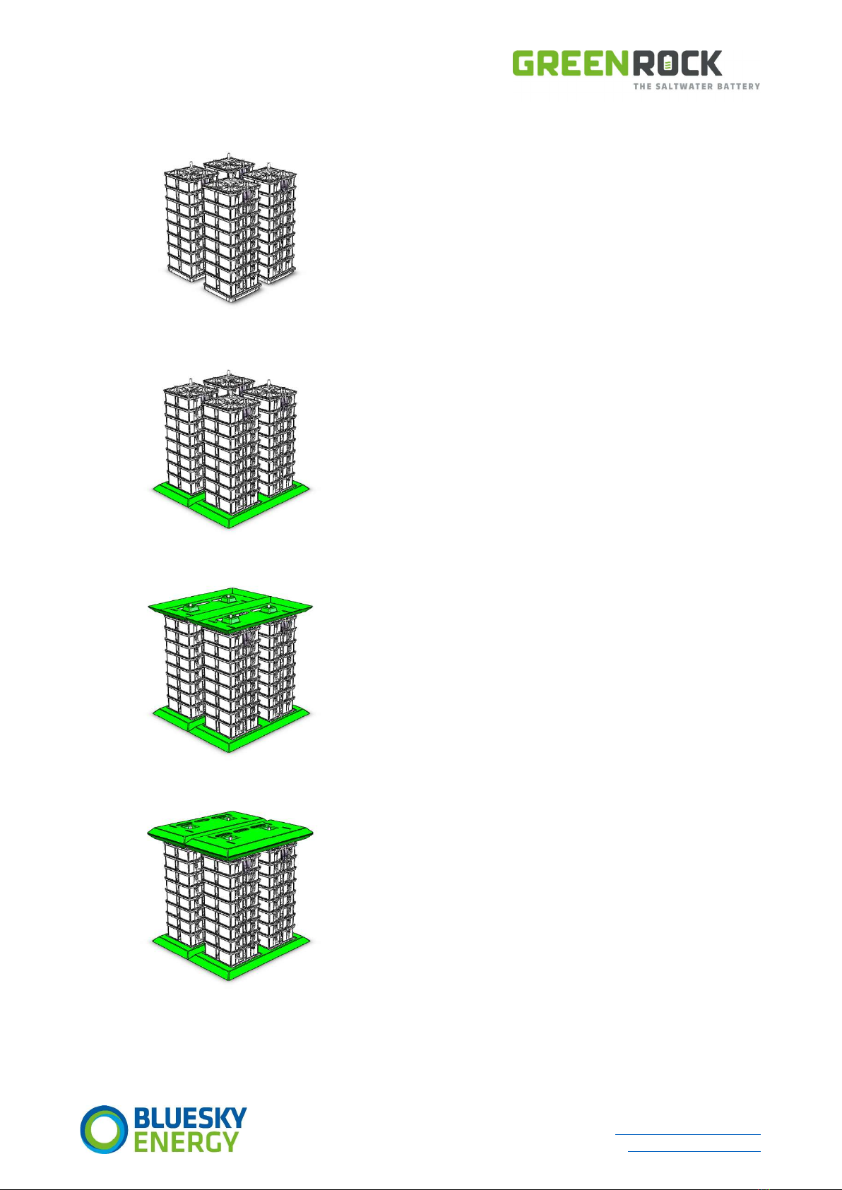
5.5 Structure of GREENROCK three phase
Place the battery stacks at their destination and align
them roughly.
The cabling of the batteries must be on the front side.
Use appropriate lifting aids for this purpose.
The distance from threaded bolt to threaded bolt is
400 mm (central).
If the CLADDING option is selected:
(without which you can skip this step)
Slip over the eyeglass-shaped base plate, which
serves as a rough positioning template.
The Velcro fasteners must point outwards and
upwards.
Be careful not to damage the cabling.
Place the base/intermediate plate on the battery
stacks.
The cable openings must be located on the rear side.
Next, place and centre the base plate of the junction
box.
The cable openings must be located on the rear side.
Fornacher Strasse 12 Telephone +43 (720) 010 188
A-4870 Vöcklamarkt Email: office@bluesky-energy.eu
Austria www.bluesky-energy.eu
January 10, 2020/greenrock-heimspeicher_installations- & inbetriebnahmehandbuch_v02_en 16
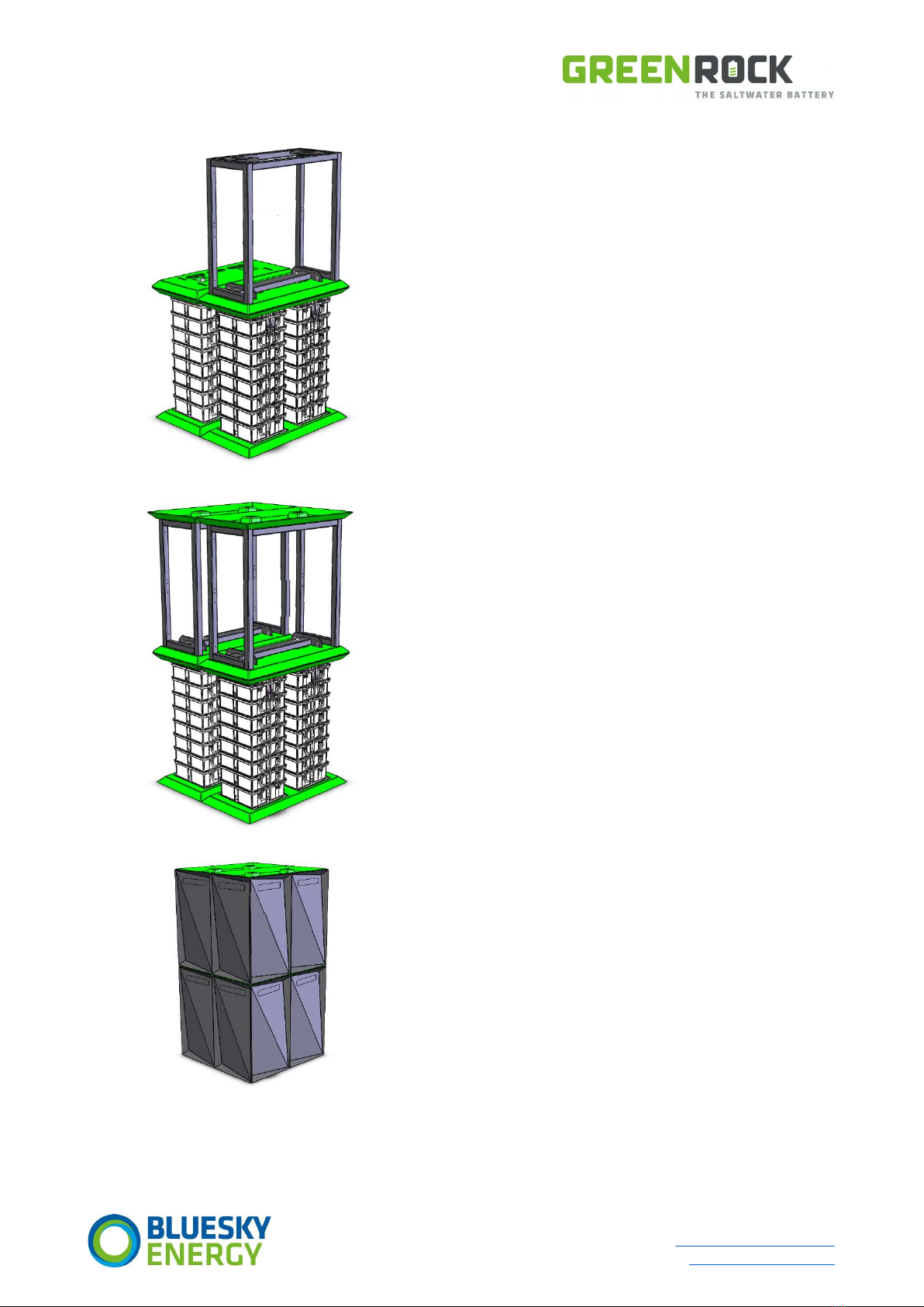
Place the junction box with the GREENROCK EMS on
the front base plate.
Make sure that the cover is mounted on the inverter
frame.
The Velcro fasteners of the lid cover must point
outwards and down.
Centre the junction box so that the spacer bolts
engage in the holes of the cross brace of the box.
Make sure that the junction box is firmly fixed.
Fasten the junction box with the enclosed M16
screws with a torque of 30 Nm.
Optionally it is also possible to fix the junction box(es)
to a wall using a wall mounting set.
Place the second junction box on the rear base plate.
Make sure that the cover is mounted on the inverter
frame.
Centre the junction box so that the spacer bolts
engage in the holes of the cross brace of the box.
Make sure that the junction box is firmly fixed.
Fasten the junction box with the enclosed M16
screws with a maximum torque of 30 Nm.
The cladding parts are attached by means of the pre-
assembled Velcro points.
Cladding of the battery stacks: OPTIONAL.

Fornacher Strasse 12 Telephone +43 (720) 010 188
A-4870 Vöcklamarkt Email: office@bluesky-energy.eu
Austria www.bluesky-energy.eu
January 10, 2020/greenrock-heimspeicher_installations- & inbetriebnahmehandbuch_v02_en 17
5.6 Cladding batteries - What to consider
When placing and assembling the cladding parts,
make sure that single and/or double versions are
used correctly.
Observe the version marked red in the illustration.
Double cover over double base.
Single cover over single base.
Make sure that the Velcro fasteners of the battery
cover point down and outwards.
The cladding parts of the batteries are not
symmetrical. Make sure that the long side faces
outwards.
5.7 Tilt protection
Due to the size of the system, the frame of the system has to be mounted with an anti-tilt device by means of wall hooks, which
achieves a pulling force of 8 kg.
This tilt protection can be mounted directly on the top mounting rail/metal rail inside the device.
5.8 Wall mount
As an option, the junction box can also be mounted on a wall using a wall bracket. When choosing this option, you will receive all
necessary documents for assembly and installation.
Fornacher Strasse 12 Telephone +43 (720) 010 188
A-4870 Vöcklamarkt Email: office@bluesky-energy.eu
Austria www.bluesky-energy.eu
January 10, 2020/greenrock-heimspeicher_installations- & inbetriebnahmehandbuch_v02_en 18
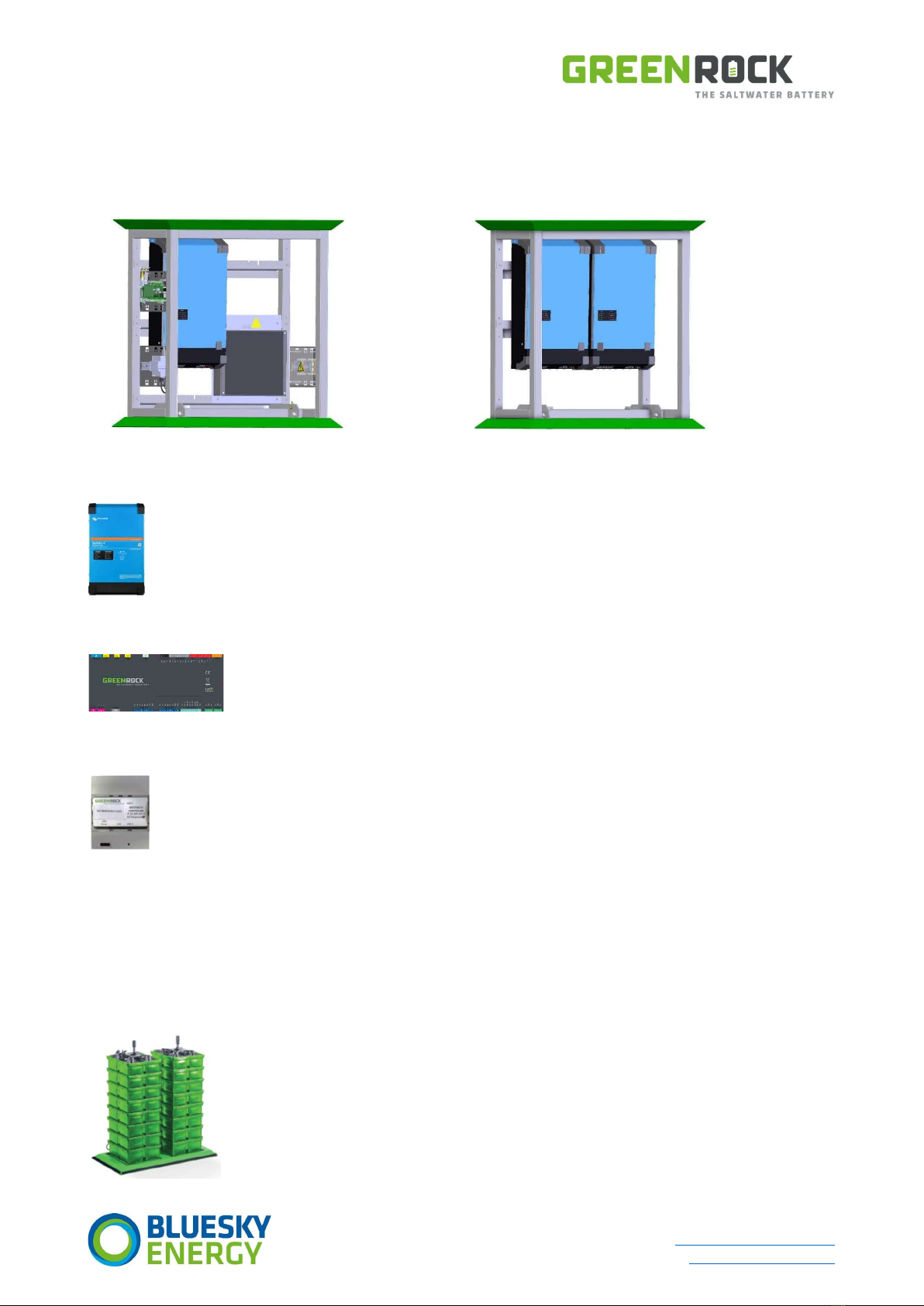
(6) GREENROCK HOME ENERGY STORAGE - SYSTEM
COMPONENTS
The GREENROCK Home Energy Storage consists of the following main components:
Basic junction box for single-phase and three-phase systems Additional junction box for three-phase systems
6.1 Power inverter
The inverters used serve to convert AC power into DC power (charger function) and to convert DC power into AC
power (inverter function). Currently, inverters from Victron Energy are used in GREENROCK Home Energy Storage
systems. A single-phase system contains 1 inverter (L1); 3-phase systems contain 3 inverters with one device per phase
(L1 - L3).
6.2 GREENROCK Energy Management System (EMS)
The GREENROCK EMS (Energy Management System) is the heart of the application.
It represents the core of the application, takes care of the recording of all relevant system data such as
surplus, intake, PV generation and own consumption, takes over the entire control of all applications and
ensures optimum operation of the entire system.
6.3 GREENROCK controller
The GREENROCK controller as interface for the inverters and the Energy Management System (EMS).
6.4 Combiner Board (DC distribution)
The Combiner Board serves as DC distribution for all DC generators (inverter/charger and photovoltaic charge controller) as well as
for the saltwater batteries. Furthermore, a battery monitoring system (BMS) is implemented on the Combiner Board.
Terminal
The terminals are the interface between the internal and external cabling.
6.5 Battery stacks
The 48 V saltwater battery stack is the cornerstone of the scalable energy solutions from
BlueSky Energy. It connects eight battery cells switched in series to a 48 V product.
6.1
6.2
6.4
6.3
6.5
6.1
6.1

Fornacher Strasse 12 Telephone +43 (720) 010 188
A-4870 Vöcklamarkt Email: office@bluesky-energy.eu
Austria www.bluesky-energy.eu
January 10, 2020/greenrock-heimspeicher_installations- & inbetriebnahmehandbuch_v02_en 19
(7) ELECTRICAL INSTALLATION
WARNING
The electrical installation of the GREENROCK Energy Storage system may only be carried out by a qualified
electrician.
Measures
Five safety guidelines
1. Disconnect.
2. Secure against restarting.
3. Ensure that there is no voltage.
4. Earth and short-circuit.
5. Cover or enclose adjacent live parts.
CAUTION
The electrical installation must be carried out in accordance with the applicable regional standards and directives.
Measures
Observe the applicable regional standards and guidelines!
Please contact your energy supplier before installation!
CAUTION
The poles of the battery stacks of the GREENROCK energy storage are always live; appropriate precautions are
necessary.
Measures
Do not place any tools or other material on the battery stacks.
Use only insulated tools when working on the energy storage unit.
Fornacher Strasse 12 Telephone +43 (720) 010 188
A-4870 Vöcklamarkt Email: office@bluesky-energy.eu
Austria www.bluesky-energy.eu
January 10, 2020/greenrock-heimspeicher_installations- & inbetriebnahmehandbuch_v02_en 20
7.1 Connection of the battery stacks
WARNING
Before the battery stacks are connected to the Combiner Board, the stack voltage must be measured and
compared! If the voltages of the individual battery stacks deviate by more than 3 V (48 V systems), measures must
be taken.
Measures
The individual battery stacks must be brought to the same voltage with a charger suitable for batteries.
In this case, contact BlueSky Energy.
If the batteries are within the voltage limits described above, you can connect the battery stacks to the Combiner Board.
The GREENROCK Energy Storage systems already include the entire cabling and protection for the DC side. The system is a 48 V
safety extra-low voltage system. Each battery stack is individually fused with a 20 A gG fuse at the positive pole.
Before you start with the installation of the energy storage, you must ensure that all fuse isolators between the battery
stacks and the DC distributor (Combiner Board) are open!
The fuse isolators for the battery stacks are located under the cover of the Combiner Board!
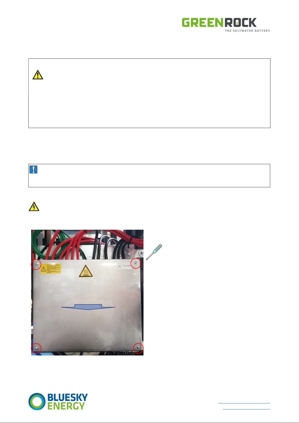
7.1.1 Opening the cover of the Combiner Board
If the system is in operation, please read the chapter “Switching off the HOME ENERGY STORAGE” before opening the
Combiner Board cover!
After the GREENROCK Home Energy Storage has been switched off, the Combiner Board cover can be removed by loosening the 4
cover screws.
Table of contents
Popular Storage manuals by other brands

Western Digital
Western Digital WDH2Q20000 - My Book Studio Edition II Hard Drive... install guide

Seagate
Seagate BARRACUDA ST1000DM008 product manual

Western Digital
Western Digital My Cloud user manual

Hitachi
Hitachi Deskstar 180GXP Quick installation guide

RunCore
RunCore SSD Pro IV product manual

Team
Team mostash user guide

ATESS
ATESS BC Series user manual

Overland Storage
Overland Storage SnapServer DX2 quick start guide

Cryotherm
Cryotherm BIOSAFE 120 operating manual

Seagate
Seagate Constellation ES.3 ST4000NM0033 product manual

CEStronics
CEStronics OMEGA FLEX Destop Writer DTW operating instructions

Seagate
Seagate DB35.2 product manual


