Cryotherm BIOSAFE 120 User manual
Operating Manual
BIOSAFE® 120 / 220 / 420 MDß
Service – Hotline:
+49 (0) 2741-95 85 75


Inhalt
I
Seite
1Introduction 1
1.1Symbols in the Manual 1
1.2Principle 2
1.3Delivery 2
2Component Overview 3
3Cryogenic Storage Vessels
CHRONOS®120/220/420 4
3.1Specifications of the Vessels CHRONOS®
120/220/420 4
3.2Structure of the Vessel 6
3.2.1Combined Positive Pressure Relief and Seal-off
Device 6
3.2.2Castors / Transport possibilities CHRONOS®120 7
3.2.3Castors / Transport possibilities CHRONOS®
220/420 8
3.2.4Cover CHRONOS® 120 9
3.2.5Cover / Elevating Mechanism CHRONOS®
220/420 10
3.2.6Storage Shelf / Storage Frame 12
3.2.7Connection for Level Control Unit and Vessel
Control System BIOSAFE – CONTROL® ß 12
3.2.8Fill Connection 13
4Level Control Unit and Vessel Control System
BIOSAFE-CONTROL®ß 14
4.1Functions 14
4.2Operating Elements 23
4.3Assembly / Commissioning 24
4.4Normal Operation 24
5Safety 26
5.1Safety advices 26
5.2How to handle liquid Nitrogen 26
5.3General Safety Instructions 26
5.4Proper Use according to the Regulations 26
5.1Safety Safety advices “Handling with cryogenic
liquefied gases” Source: IGV Germany 27
5.2Note Road Transportation 31
5.3Labelling 32
6Transport and Assembly 33
6.1General Transport 33
6.2Assembly 34
7Operation 35
7.1Installation / Assembly 35
7.1.1Assembly of the Fill Line 35
7.1.2Assembly of BIOSAFE-CONTROL®ß 36
7.1.3Connection of the liquid Nitrogen Supply 36
7.2Initial Commissioning 37
7.3Normal Operation 38
7.4Storing and Taking-out of Samples 40
7.5Putting out of Operation / Cleaning 41
Contents
Introduction
II
8Accessories 42
8.1.1Sorting System CHRONOS®120 42
8.1.2Sorting System CHRONOS®220 45
8.1.3Sorting system CHRONOS®420 48
9Maintenance / Repair 52
9.1Scope of Maintenance 52
9.2Declaration of Decontamination 54
9.3Spare Parts 55
10Faults 56
10.1General 57
10.2Possible Faults CHRONOS®58
11Warranty 60

Introduction
1
BIOSAFE ®120/220/420 MDß is a medical device of Class II a
according to Directive 93/42/EWG of the Council of 14 June
1993 for medical devices.
With the medical device BIOSAFE®120/220/420 MDß for
example the following cell and tissue samples are long-term
stored by using liquid nitrogen (LIN) as cryogenic agent at
temperatures below -130° C for the return into the human
being:
•sperm, ovum
•ancestral cells, bone marrow
•blood components, e. g. erythrocytes
•heart valves
•skin, bones, teeth
as well as e. g.
•samples for the DNA – analysis in gene technology
The preconditions for this are
•that the samples are tightly packed in packaging suitable for
liquid nitrogen temperatures.
•that the samples were deep-freezed correctly.
•That the medical device BIOSAFE®120/220/420 MDß is
operated properly according to the regulations.
Informs of dangerous situations resulting in possi-
ble
•Personal injuries
•Environmental damage
•Machinery damage
Voltage hazard
Indicates
•Advices
•Exemplifications
•Supplements
Warning of Squeezing Danger
1 Introduction
1.1 Symbols in the Manual
Introduction
2
The medical device BIOSAFE®120/220/420 MDß may only
be operated according to this operating manual.
Before commissioning, it is absolutely necessary to read
the operating manual completely.
The BIOSAFE®120/220/420 MDß may only be operated by
trained and instructed personnel.
Immediately after receipt of the unit, check delivery with
regard to
•completeness
•damage
In case of transport damage, inform
•transport insurance
•transport company
•supplier
1.2 Principle
1.3 Delivery

Component Overview
3
The medical device BIOSAFE®120/220/420 MDßconsists of
two components:
•Level control unit and vessel control system BIOSAFE –
CONTROL®ß, with level probe, temperature probe, evalua-
tion software for PC and holding device at CHRONOS®
120/220/420
•Cryogenic Storage Vessel CHRONOS®120/220/420 with
designer cover with vacuum insulated panel, solenoid
valve, cover switch and safety intermediate piece under a
cover, insulated decanting hose
Optional component:
•„I / O Box“ for connecting external alarms, main shut-off
valve, analogue output for temperature documentation
Accessories:
Sale by:
Cryotherm GmbH & Co. KG
•aluminum sorting system
No medical device
2 Component Overview

Cryogenic Storage Vessels CHRONOS®120/220/420
4
3 Cryogenic Storage Vessels
CHRONOS®120/220/420
3.1 Specifications of the Vessels
CHRONOS®120/220/420
CHRONOS®
120
CHRONOS®
220
CHRONOS®
420
1. Width B 56 cm 72 cm 90 cm
2. Depth T 70 cm 85 cm 103 cm
3. Total height of Vessel H
(cover closed) 112 cm 120 cm
119 cm
4. Assembly width A 80 cm 80 cm 96 cm
5. Assembly depth D 80 cm 75 cm 95 cm
6. Assembly width
BIOSAFE-CONTROL®ß
80 cm 95 cm
110 cm
7. Height with
BIOSAFE-CONTROL®ß 125 cm 125 cm
125 cm

Cryogenic Storage Vessels CHRONOS®120/220/420
5
CHRONOS®220 CHRONOS®420
8. Vessel height, cover opened H1 107 cm 107 cm
9. Space required: Depth F 91 cm 116 cm
10. Space required: Width G 141 cm 175 cm
11. Space required: Distance J 42 cm 62 cm
12. Space required: Distance J1 55 cm 75 cm
13. Space required: Height H3 137 cm 137 cm
14. Space required: Height H4 168 cm 168 cm
Behälte
G
D
Wand
H
Deckel
Behälte
J
Position Deckel
J

Cryogenic Storage Vessels CHRONOS®120/220/420
6
Caution! The positive pressure relief and seal-off
device protects the vacuum room from overpres-
sure. Re-evacuation may only be carried out by
•manufacturer’s skilled staff
The protective cover (2) intercepts the valve insert
(1), when there is overpressure existing in the vacu-
um room.
•Do not remove the protective cover (2).
•Protect the valve from heat as well as cooling, as
brittleness results in the loss of the operating vacuum.
CHRONOS®
120 CHRONOS®
220 CHRONOS®
420
Total geometrical capacity 151 251 415 l
Geometrical capacity below the
storage shelf (LIN reserve) 21 35
57 l
Geometrical capacity above the
storage shelf (cubic capacity) 130 216
358 l
1decimetre filling height corre-
sponds to
21 35 57 l
Operating overpressure 0 0 0 bar
Empty weight 100 175 225 kg
Outside diameter 560 710 900 mm
Inside diameter 514 664 854 mm
Storage height 625 625 625 mm
Operating height (upper edge of
the vessel with open cover) 1045 1070
1070 mm
Total height 1150 1180 1190 mm
Roller diameter 80 80 Mm
Static rate of evaporation
(measured with gas phase stor-
age)
2,3
3,5
2,0
5,0
1,5
≈6,2
%/d
l/d
Holding time (LIN Reserve) 4,5 58 d
3.2 Structure of the Vessel
3.2.1 Combined Positive Pres-
sure Relief and Seal-off De-
vice

Cryogenic Storage Vessels CHRONOS®120/220/420
7
As an option, the cryogenic storage vessel CHRONOS® can
be equipped with a roller base. This roller base features 4
casters, 2 of which are equipped with locking levers.
Transport with roller base
It is absolutely necessary to carry out transport over
uneven grounds and stairs with 2 persons.
Transport with fork lifter
The CHRONOS®120 Vessel can be transported with a fork
lifter.
Special fork lifter pockets are not provided. Therefore, it is
absolutely necessary to secure the vessel with conventional
means during the transport with a fork lifter.
Danger of tumbling down during unsecured transport.
It is absolutely necessary to secure the vessel at the fork
lifter with suitable means (tightening straps) before
transport.
3.2.2 Castors /
Transport possibilities
CHRONOS®120
Cryogenic Storage Vessels CHRONOS®120/220/420
8
The cryogenic storage vessel CHRONOS®220 is equipped
with 2 fixed castors without locking levers in the rear area and
two adjusting feet in the front area. Thus, it is ensured that the
vessel is stable in operating condition and cannot be moved
without special devices
For the transport of Vessel CHRONOS®220/420,two
possibilities are given:
- by means of the additional transport device (article no.
78202830)
- by means of a fork lifter
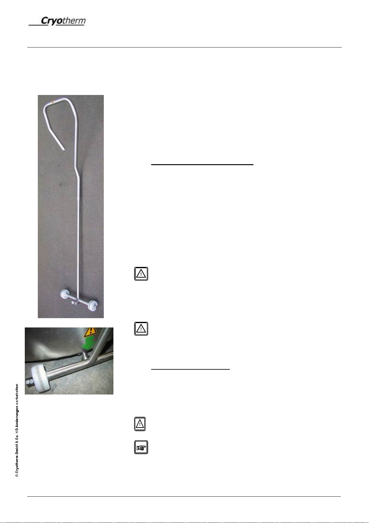
Transport with transport device
The transport device (article no. 78202830) is intended for
transporting vessels over small or middle distances (mainly
inside buildings) and for shunting inside the laboratory.
The transport device is a frame with handle, two castors and a
hemispherical journal placed in the lower area.
At the vessel bottom (in the front area), there exists the
corresponding accommodation for hemispherical journals of
the transport device (marked with a green arrow label).
By means of the transport device, the vessel is slightly lifted in
front, is thus placed on four castors and can be moved.
Danger: trapping of the fingers
By means of the transport device, hindrances up to a height /
depth / width of 20 mm (e. g. steps) can be overcome.
.
Danger: Due to the weight of the vessel, the handle of the
transport device can hit back. Do not let go of the
transport device during transport.
Transport with fork lifter
The CHRONOS®220/420 Vessel can be transported with a
fork lifter.
Special fork lifter pockets are not provided. Therefore, it is
absolutely necessary to secure the vessel with conventional
means during the transport with a fork lifter.
Danger of tumbling down during unsecured transport.
It is absolutely necessary to secure the vessel at the fork
lifter with suitable means (tightening straps) before
transport.
3.2.3 Castors /
Transport possibilities
CHRONOS® 220/420

Cryogenic Storage Vessels CHRONOS®120/220/420
9
Adjustable feet (CHRONOS 220/420)
The feet at CHRONOS 220/420 can be adjusted in height.
For this, loosen the upper lock nut first and then adjust the foot
with the lower nut in height or depth.
Subsequently, tighten the upper lock nut again.
CAUTION
Do not unscrew the foot completely!
The vessel is equipped with a detachable cover. The cover
reduces the penetration of humidity and minimizes the
penetration of additional heat into the vessel.
A lock is integrated in the cover. Thus, the access to the
contents of the vessel is limited.
Danger at the lock: trapping of the fingers
For handling the cover, two cover handles are provided.
The handles of the vessel are exclusively intended for
operating the cover and must not be used for any other
purposes.
Opening of the vessel cover
First of all, unlock the lock for opening the vessel. After that,
the cover has to be lifted.
Should any frost formation be apparent at the cover,
remove it with open cover!
Closing the vessel cover
For closing the vessel cover, put the cover on the vessel
again. Shut the lock after closing.
Danger at the lock: trapping of the fingers
3.2.4 Cover
CHRONOS® 120

Cryogenic Storage Vessels CHRONOS®120/220/420
10
The vessel is equipped with a liftable - slewable cover. The
cover reduces the penetration of humidity and minimizes the
penetration of additional heat into the vessel.
A lock is integrated in the cover. Thus, the access to the
contents of the vessel is limited
Danger at the lock: trapping of the fingers
For handling the cover, two cover handles are provided.
The handles of the vessel are exclusively intended for
operating the cover and must not be used for any other
purposes.
Cover opening mechanism
The cover opening mechanism serves for facilitating the
opening and closing of the cover. The cover opening
mechanism consists of a lifting mechanism with integrated gas
pressure spring.
The pressure inside the gas pressure spring is adjusted in
such a way that the cover cannot leave the vessel completely
itself. This pressure ensures the perfect function of the cover
opening mechanism
The pressure inside the gas pressure spring has to be
examined during the annual maintenance and readjusted,
if necessary.
Opening of the vessel cover
First of all, unlock the lock for opening the vessel. After that,
the cover has to be lifted upwards to the limit stop and
subsequently swivelled aside. In tilt-out condition the cover is
blocked and protected against falling down.
After opening, block the cover by tilting-out aside.
Possible frost formation at the cover edge can possibly
result in the fact that the cover does not move upwards
itself after opening the lock handle.
For opening, loosen the cover at the handles with lateral
movements and moderate pulling upwards.
Should any frost formation be apparent at the cover,
remove it with open cover!
3.2.5 Cover / Elevating Mecha-
nism
CHRONOS® 220/420

Cryogenic Storage Vessels CHRONOS®120/220/420
11
Closing the vessel cover
For closing the vessel cover, swing back the cover first, so that
the cover is located above the vessel. At the same time, the
blocking is loosened. After that, carefully lower the cover. Shut
the lock after closing.
Danger at the lock: trapping of the fingers
EMERGENCY - PROCEDURE
In case that the lifting mechanism is obviously blocked with
closed or opened cover, carry out the following emergency -
procedure after consulting the CRYOTHERM – SERVICE
(Hotline: 02741 – 95 85 75):
Opening: Loosen 4 fastening screws between cover and
lifting mechanism. The cover can then be lifted
with 2 persons.
Closing: Loosen the cover as described and insert into the
vessel as much as possible in slightly turned po-
sition.
Cryogenic Storage Vessels CHRONOS®120/220/420
12
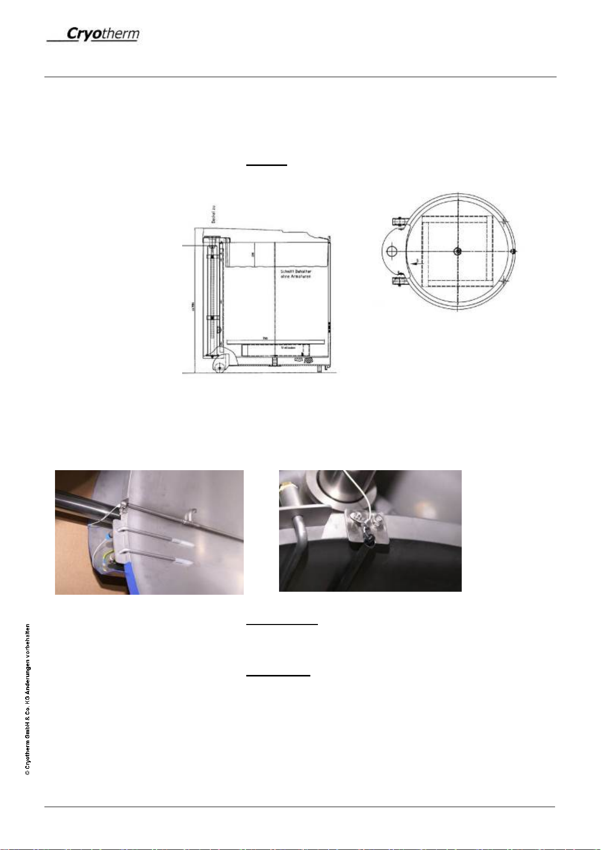
The storage shelf is a storage level loosely inserted into the
vessel and is located on a storage frame made of aluminum.
Picture:
CHRONOS® 220/420
Right picture:
The level probe of BIOSAFE-CONTROL® ß is inserted into the
splash guard pipe (center) provided for this.
Left picture:
Between the LIN fill line (left) and the splash guards pipe
(right) for the level probe, there exists the instrument leads for
the temperature probe of the BIOSAFE-CONTROL®ß
3.2.6 Storage Shelf / Storage
Frame
3.2.7 Connection for Level Control
Unit and Vessel Control Sys-
tem
BIOSAFE – CONTROL® ß

Cryogenic Storage Vessels CHRONOS®120/220/420
13
The fill connection is a detachable 3/8” screwed pipe.
At this connection, the decanting of the LIN supply is
connected.
The fill pipe ends inside the vessel below the cover insulation
and is slightly bevelled.
It prevents the splashing of the level probe or of the sorting
system.
3.2.8 Fill Connection

Level Control Unit and Vessel
Control System
BIOSAFE-CONTROL® ß
14
Languages
•The device display readings and the PC software can
be set to German or English. Combinations are pos-
sible, too, i. e. German display and English PC soft-
ware or German PC software and English display.
Level control
•The level of the liquid nitrogen inside the storage ves-
sel is kept between minimum and maximum.
•If the level falls below minimum, a solenoid valve is
triggered and liquid nitrogen continues flowing into the
storage vessel.
•A delayed reaction between 0 and 999 minutes can
be selected for the magnetic valve (1). This delay
cannot be set for “Filling after Min. Alarm” and “Manu-
al Filling”.
•The filling procedure is stopped as soon as the level
reaches the maximum level.
•If the level falls below the minimum alarm level or
exceeds the maximum alarm level, a visual and
acoustic alarm is triggered. In addition, an alarm out-
put is connected..
•The level and the operating states are displayed both
at the device and at the PC.
•Delay times for triggering an alarm can be set both at
the device and via PC.
•All alarms can only be activated or deactivated via a
service menu in the PC software (1). This menu can
only be accessed by service personnel. At the time of
delivery ex works all alarms are activated.
•With opened cover, automatic refilling is suppressed.
Manual refilling (e. g. for unfogging) is possible.
•The distances between the sensors of the level probe
(standard design) are as follows:
Minimum alarm to minimum: 3 cm
Minimum to maximum: 4 cm
Maximum to maximum alarm: 3 cm
•Alternatively there is a level control probe spaced at
2 cm/2cm/2cm. If required, please contact the
manufacturer or service.
•In order to set the requested level in the storage ves-
sel, the vessel probe has to be inserted more or less
deeply into the instrument leads provided for this.
4 Level Control Unit and Vessel
Control System
BIOSAFE-CONTROL®ß
4.1 Functions
Level Control Unit and Vessel
Control System
BIOSAFE-CONTROL® ß
15
Temperature - Control
•The temperature inside the storage vessel is con-
trolled, displayed (at the device and the PC) and
logged.
•If an adjustable limiting value for the storage
temperature is exceeded longer than the period of
time selected for this, an alarm is recorded, dis-
played and triggered.
•The values for the storage temperature are stored
every 15 minutes.
•If the temperature is above the limit, the log rate for
the temperature values is increased from 1 reading
every 15 minutes to 1 reading per minute. Thus the
progression up to exceeding the limiting temperature
is displayed with a higher resolution and is thus more
accurately traceable.
•A graphic evaluation of the temperature course can
be carried out via PC.
•Delay times for triggering an alarm and the maximum
allowable storage temperature can be set both at the
device and via PC
•Display range: -200 °C to +50 °C
Cover control
•The opening condition of vessel cover is determined
by means of a cover switch.
•The opening of the cover is registered and indicated.
•If an adjustable period of time is exceeded for cover
opening, an alarm is triggered.
Note:
Vessels without a cover switch must be bridged.

Level Control Unit and Vessel
Control System
BIOSAFE-CONTROL® ß
16
Display/Indication
•The display language can be set to German or Eng-
lish.
•On the display are indicated;:
- storage temperature
- level (between minimum and maximum)
- messages (operating state, information, alarm
messages)
•In addition, the
- vessel no. (= ID) (1 to 32)
- date and time (prevailing)
- date and time of an occurred alarm message
and
•information on:
- data connection to the Master („M“)
- automatic refilling is triggered („F“)
- device is switched „inactive“ ( „ i “ )
are indicated.
•With alarm messages, the background lighting of the
display flashes.
Acoustic and visual alarm
•With alarm messages, the background lighting of the
display flashes.
•On the display, the prevailing alarm is indicated in
plain text.
•In addition to the visual alarm message, an acoustic
warning takes place.
This manual suits for next models
2
Table of contents


