Blue Star J Series User manual

User’s Manual
Hi-Wall Split Air Conditioners
(J Series &D Series - T3 Fixed Speed Cool Only)

First Published - July, 2018
No part of this publication may be reproduced in any manner
whatsoever without permission in writing from the CEO,
Blue Star International FZCO.
Blue Star International FZCO is a wholly owned subsidiary of Blue Star Limited, India.
While due care has been taken to avoid errors or misinterpretation,
Blue Star Limited or Blue Star International FZCO is neither liable nor
responsible for consequence of any action taken on the basis of this publication.
All contents applicable as on date of publication.
Modications may take place subsequently.
Published by
Blue Star International FZCO
Unit No: 3E - 520, Building No: 3E (East Side),
Dubai Airport Free Zone, Dubai, UAE
PO Box No: 293719Trade Licence No: 3331
Email: [email protected]
Visit us at: www.bluestarindia.com
For restricted circulation only. Not for sale.
2
Hi-Wall Split Air Conditioner

3
User’s Manual
Table of Contents
Letter from the CEO ........................................................................................4
Safety Instructions ................................................................................................5
Preparation Before Use ....................................................................................................................6
Safety Precautions .............................................................................................................................7
Identification of Parts
Indoor Unit ...................................................................................................................................................8
Outdoor Unit ................................................................................................................................................8
Display Introduction..................................................................................................................................9
Maintenance ..............................................................................................................................................11
Protection ...................................................................................................................................................12
Troubleshooting ........................................................................................................................................13
Installation Instructions
Installation Diagram ...............................................................................................................................14
Select the Installation Location ............................................................................................15
Indoor Unit Installation ...................................................................................................................16
Outdoor Unit Installation ................................................................................................................21
Air Purging ...........................................................................................................................................22
Notes ........................................................................................................................................34
E-Waste Management ......................................................................................................... Back Page Inner
Remote Controller .............................................................................................................................23
Models Range ......................................................................................................................................30
Customer Care .....................................................................................................................................32

4
Dear Customer,
Congratulations on the purchase of your new high performance and energy-ecient Blue Star product,
one amongst the many world-class solutions that Blue Star manufactures and markets around the globe.
This superior product has been designed for optimum performance even under harsh ambient conditions.
Ithasbeenmanufacturedwiththebest availablematerials,withstringentqualitycontrolmeasuresundertaken
during all the manufacturing processes. It has been tested under actual operating conditions in our factory
labs to ensure that you get years of satisfactory and trouble-free performance.
We are condent that time and performance will justify the trust you have placed in this product.
This manual will help you get the best out of your machine.We urge you therefore to spare some time to go
through it in detail.
In the unlikely event of your product running into a problem, kindly first check the Troubleshooting
Chart contained in this manual. There may be a simple solution to the problem. If this does not
help, please contact your nearest Blue Star dealer for expert assistance. You can also reach us on
We look forward to a long and mutually satisfying association with you.
With warm regards,
Dawood Bin Ozair,
Chief Executive Ocer,
Blue Star International FZCO
Letter from the CEO
Hi-Wall Split Air Conditioner

5
User’s Manual
Safety Instructions
To guarantee the unit works normally, please read the manual carefully before installation,
and try to install strictly according to this manual.
Do not let air enter the refrigeration system or discharge refrigerant when moving the air
conditioner.
Earth the air conditioner properly.
Check the connecting cables and pipes carefully, make sure they are correct and firm before
connecting the power of the air conditioner.
There must be an air-break switch.
After installing, the consumer must operate the air conditioner correctly according to this
manual, keep a suitable storage for maintenance and moving of the air conditioner in the
future.
Type of fuse used on indoor unit controller is 5x20, with rating 3.15 A / 250 V.
A residual current device (RCD) with the rating of above 10mA shall be incorporated in the
fixed wiring according to the national rule.
Warning: Risk of electric shock can cause injury or death. Disconnect all remote electric
power supplies before servicing.
Recommended pipe should not exceed 5m. If need to exceed the pipe length, U Trap is
required after every 5m length for oil return to the compressor.
This appliance can be used by children aged from 8 years and above and persons with the
reduced physical, sensory or mental capabilities or lack of experience and knowledge if they
have been given supervision or instruction concerning the use of the appliance in a safe way
and understand the hazards involved. Children shall not play with the appliance. Cleaning
and user maintenance shall not be made by children without supervision.
The batteries in remote controller must be recycled or disposed of properly. Please discard
the batteries as sorted municipal waste at the accessible collection point.
If the supply cord is damaged, it must be replaced by the manufacturer, its service agent or
similarly qualified person in order to avoid a hazard.
The appliance shall be installed in accordance with national wiring regualtions.
The air conditioner must be installed by professional or qualified persons.
The appliance shall not be installed in the laundry area / washroom.
The temperature of refrigerant circuit will be high, please keep the interconnection cable
away from the copper tube.
Warning: Electrical instructions
Power supply: the electrical installation must be in accordance with the local power
standard in particular for earthing plug. We cannot be held responsible for any
incident caused by a faulty electrical installation.
Advises for the electrical installation of your device:
- Don't use receptacle extension, adapter or multiple receptacle
- Never eliminate the earthing plug
- The electrical outlet must be easily accessible but out of reach from children
In case of doubt, please contact installer.

Preparation before use
Before using the air conditioner, be sure to check and preset as the following.
Back-light function
Hold down any button of the remote controller for about 2 seconds, the back-light
will be turned on. It will be turned off automatically after about 10 seconds.
Remote Controller presetting
Each time after the remote control is replaced with new batteries or is energized,
remote control auto presetting heat pump. If the air conditioner you purchased is
a Cooling Only one, heat pump remote controller can also be used.
Auto Restart Presetting
The air conditioner has Auto-Restart function, you can set or cancel this function
when the air conditioner is running.
Hold down the emergency button (ON/OFF) for a few seconds, this function
will be set if you hear beep twice. If you just hear beep once, this function will
be cancelled.
Safeguarding the environment
This marking indicates that this product should not be disposed
with other household wastes throughout the EU. To prevent possible
harm to the environment or human health from uncontrolled waste
disposal, recycle it responsibly to promote the sustainable reuse of
material resources. To return your used device, please use the return
and collection systems or contact the retailer where the product was
purchased. They can take this product for environmental safe
recycling.
6
Hi-Wall Split Air Conditioner

Do not keep any objects on the outdoor
fire may break out
to let the air flow be deflected to entire
room speeds, this may cause an injury
Symbols in this manual are interpretated as shown below.
sure
the cord, else the power cord will break.
An electric shock or fire may be caused
7
User’sManual
Safety Precautions
Keep the power supply circuit breaker
or plug away from dirt. Connect the
power supply cord to it firmly and
correctly. Insufficient contact might
lead to shock or fire break out.

The figures in this manual are based on the external view of a standard model.
Consequently, the shape may differ from that of the air conditioner you have selected.
Air Intake
Air Outlet
Air Outlet
Horizontal Adjustment
Louver
Air Filter
Remote Controller
Pipes and Power
Connection Cord
Emergency Panel
Display Panel
Drain Hose
Note: Condensate water drains at
COOLING or DRY operation.
Identification of parts
Air Intake
Front Panel
O
O
F
N
F
MODE
SMART
QUIET DIMMER
ECONOMY
FEEL
SUPER
FAN SPEED
CLOCK
TIMER ON
TIMER OFF
SLEEP
TEMP.
TEMP.
Vertical Adjustment
Louver
8
Hi-W all Split Air Conditioner

DA Series
9
User’s Manual

Dplay inducon
Emergency button
ON/OFF To let the AC run or stop by pressing the button.
10
Hi-Wall Split Air Conditioner
DJ Series

Maintenance
Note: It is necessary to clean the
air filter after using it for about
100 hours.
Front panel maintenance
Air filter maintenance
Never use volatile substance
such as gasoline or polishing
powder to clean the appliance.
Clean and reinstall the air filter.
Close the front panel again.
shock!
Electric
Dangerous!
Wipe with a soft
and dry cloth.
Use soft moisture cloth to
clean if the front panel is
very dirty.
Never sprinkle water onto the
indoor
unit
Reinstall and shut the front panel.
Reinstall and shut the front panel by
pressing position "b" downward.
If the dirt is conspicuous, wash
it with a solution of detergent
in lukewarm water. After
cleaning, dry well in
shade.
Clean the air filter every two weeks if
the air conditioner operates in an
extremely dusty environment.
Stop the appliance, cut off the
power supply and remove the air
filter.
1
23
1.Open the front panel.
2.Press the handle of the filter gently
from the front.
3.Grasp the handle and slide out the filter.
soft cloth to
clean it.
Use a dry and
bb
Turn off the appliance first
before disconnecting from
power supply.
Cut off the power supply a
Grasp position "a" and pull
outward to remove the
front panel. a
11
User’s Manual

Protection
Operating condition
The protective device may trip and stop the appliance in the cases listed below:
COOLING
DRY
Outdoor air temperature is over 55oC
Room temperature is below 21oC
Room temperature is below 18oC
Noise pollution
Install the air conditioner at a place that can bear its weight in order to operate more quietly.
Install the outdoor unit at a place where the air discharged and the operation noise would not annoy your
neighbours.
Do not place any obstacles in front of the air outlet of the outdoor unit lest it increases the noise level.
Features of protector
If all operation has stopped, press ON/OFF button again to restart, Timer should be set again if it has been
cancelled.
The protective device will work for the following cases:
Restarting the unit after operation stops or changing mode during operation, you need to wait for 3
minutes.
Connect to power supply and turn on the unit at once, it may start 20 seconds later.
Defrost
Features of HEATING mode (Not Applicable)
Preheat
At the beginning of the HEATING operation, the airflow from the indoor unit is discharged 2-5 minutes later.
In HEATING operation the appliance will defrost (de-ice) automatically to raise efficiency. This
procedure usually lasts 2-10 minutes. During defrosting, fans stop operation.
After defrosting completes, it returns to HEATING mode automatically.
1.
2.
Note: Heating mode is NOT available for cooling only air conditioner models.
The temperature of some products is allowed beyond this range. In specific situation, please consult the merchant. If the
air conditioner runs in COOLING or DRY mode with door or window opened for a long time when relative humidity is above
80%, dew may drip down from the outlet.
Hi-Wall Split Air Conditioner
12
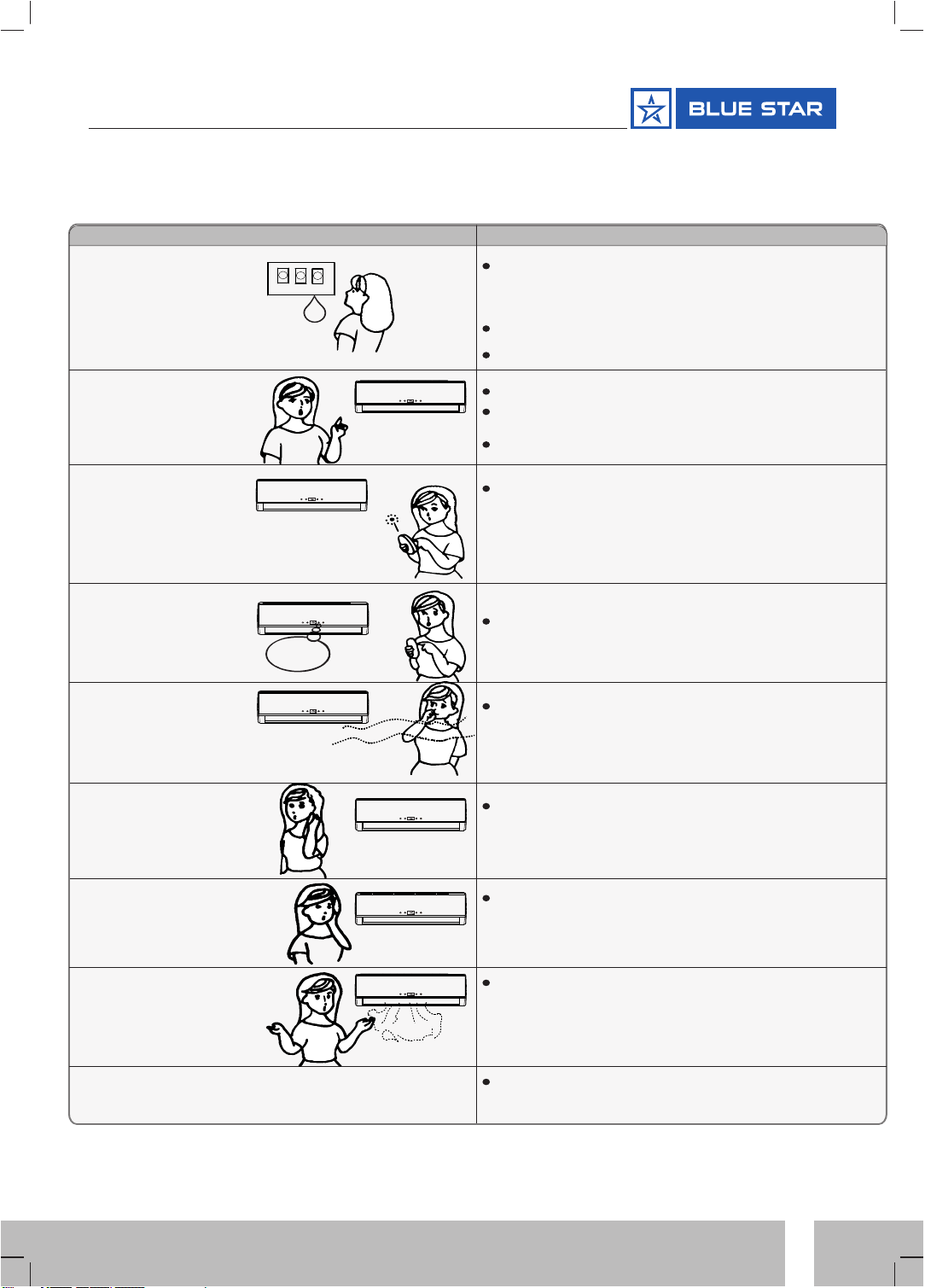
Trouble Analysis
Does not run
No cooling or
heating air
Ineffective control
Does not operate
immediately
Peculiar odor
A sound of
flowing water
Cracking sound is
heard
Spray mist from
the outlet
The compressor indicator (red) lights on constantly,
and indoor fan stops.
The unit is shifting from heating mode to defrost. The
indicator lights off within ten minutes and returns to
heating mode.
Is the air filter dirty?
Are the intakes and outlets of the air
conditioner blocked?
Is the temperature set properly?
don't run
If the protector trips or fuse is blown,
please wait for 3 minutes and start again, the
protector device may be preventing the unit to work.
.If batteries in the remote controller are exhausted.
If the plug is not properly plugged.
The following cases may not always be a malfunction, please check it before asking for service.
If strong interference (from excessive static electricity
discharge, power supply voltage
abnormality) presents, operation will be abnormal. At this
time, disconnect from the power supply and connect back
2-3 seconds later.
Changing mode during operation, there will be
a 3 minute delay.
This odor may come from another source such as
furniture, cigarette etc, which is sucked in the unit
and blows out with the air.
Caused by the flow of refrigerant in the air
conditioner, not a trouble.
The sound may be generated by the expansion or
contraction of the front panel due to change of
temperature.
Mist appears when the room air becomes very
cold because of cool air discharged from
indoor unit during COOLING or DRY
operation mode.
Troubleshooting
13
User’s Manual
Note: Heating mode is NOT available for cooling only air conditioner models.

Distance from wall
should be over 50mm
Air intake distance from
the wall should be
over 250mm
Air intake distance from the wall
over 250mm
air outlet distance from the wall
should be over 500mm
Distance from ceiling
should be over 200 mm
Distance from the wall
should be over 50mm
Distance from floor should be
over 2500mm.
should be over 250mm
Installation diagram
Above figure is only a simple presentation of
the unit, it may not match the external
appearance of the unit you purchased.
Installation must be performed in accordance with
the national wiring standards by authorized personnel only.
Installation instructions
14
Hi-Wall Split Air Conditioner

Installation instructions
Outdoor unit
Outdoor unit
Indoor unit
Indoor unit
Pipe length
Pipe length is
Height
Height
Select the installation location
Location for Installing Outdoor Unit
Where it is convenient to install and well ventilated.
Avoid installing it where flammable gas could leak.
Keep the required distance apart from the wall.
Recommended pipe should not exceed 5m. If need to
exceed the pipe length, U Trap is required
after every 5m length for oil return to the compressor.
For further piping details refer table below.
Keep the outdoor unit away from a place of greasy dirt,
vulcanization gas exit.
Avoid installing it at the roadside where there is a risk of
muddy water.
A fixed base where is not subject to increasing operation
noise.
Where there is not any blockage for air outlet.
If the height or pipe length is out of the scope of the table, please consult the merchant.
Location for Installing Indoor Unit
Where there is no obstacle near the air outlet and air can be
easily blown to every corner.
Where piping and wall hole can be easily arranged.
Keep the required space from the unit to the ceiling and wall
according to the installation diagram on previous page. Where
the air filter can be easily removed.
Keep the unit and remote controller 1m or more apart from
television, radio etc.
To prevent the effects of a fluorescent lamps, keep as far as
possible.
Do not put anything near the air inlet to obstruct it from air
absorption.
Where there is strong enough to bear the weight
and is not tend to increase operation noise and vibration.
15
User’s Manual
Installation instructions
Piping direction
1
2
3
4
trough
Note: When installing the pipe at the directions 1,2 or
4, saw the corresponding unloading piece off the
indoor unit base.
Unloading
piece
Saw the unloading piece
off along the trough
Put the piping (liquid and gas pipe) and cables through the wall hole from outside or put them through
from inside after indoor piping and cables connection complete so as to connect to outdoor unit. Decide
whether saw the unloading piece off in accordance with the piping direction.(as shown below)
3. Indoor Unit Piping Installation
Indoor
Outdoor
Wall hole sleeve
( hard polythene tube
prepared by user)
5mm
(tilt downward)
Install a sleeve through the wall hole to keep the
wall tidy and clean.
Drill a hole on the wall. The hole should tilt a little
downward towards outside.
Decide the position of hole for piping according to
the location of mounting plate.
2. Drill a Hole for Piping
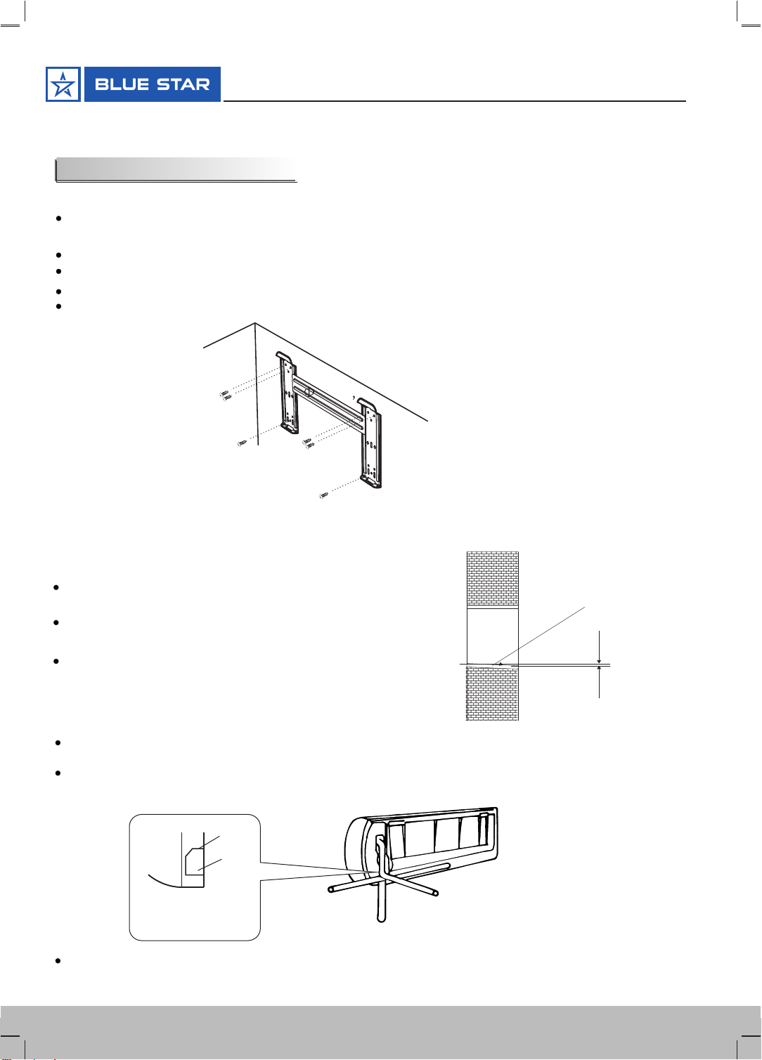
Keep the mounting plate horizontally with a horizontal ruler or dropping line.
Drill holes of 32mm in depth on the wall for fixing the plate.
Insert the plastic plugs to the hole, fix the mounting plate with tapping screws.
Inspect if the mounting plate is well fixed. Then drill a hole for piping.
1. Installing the Mounting Plate
Decide an installing location for the mounting plate according to the indoor unit location and
piping direction.
Indoor unit installation
After connecting piping as required, install the drain hose. Then connect the power cords. After connecting,
wrap the piping, cords and drain hose together with thermal insulation materials.
Mounting plate
Tapping screw
Note: The shape of your mounting plate may be different from the one above, but the installation method is similar.
Note: As the above figure shown, the six holes matched with tapping screw on the mounting plate must be used to
fix the mounting plate, the others are prepared.
16
Hi-Wall Split Air Conditioner

Installation instructions
Piping Joints Thermal Insulation:
Wrap the piping joints with thermal
insulation materials and then wrap
with a vinyl tape.
Piping Thermal Insulation:
a.
Place the drain hose under the piping.
b.
Insulation material uses polythene foam over 6mm in thickness.
Note: Drain hose is prepared by user.
Drain pipe should point downward for easy drain flow. Do not
arrange the drain pipe twisted, sticking out or wave around,
do not immerse the end of it in water.
If an extension drain hose is connected to the drain pipe, make sure
to thermal insulated when passing along the indoor unit.
When the piping is directed to the right, piping, power
cord and drain pipe should be thermal insulated and
fixed onto the back of the unit with a piping fixer.
Thermal insulation
wrapped with vinyl type
Small
pipe
Large pipe Thermal insulation
Power cord tube
Power cord 1
(for heat-pump)
Defrost cable(for heat-pump) Drain hose
(prepared by user)
A. Insert the pipe fixer to the slot.
Piping fixer Base
B. Press to hook the pipe fixer onto the base.
Base Base
Piping fixer Hook here
Insert here
drain
hose
drain
hose
large
pipe large
pipe
small
pipe
small
pipe
a. Before unscrewing the big and the small sealing caps, press the small
sealing cap with the finger until the exhaust noise stops, and then loosen
the finger.
b. Connect indoor unit pipes with two wrenches. Pay special attention
to the allowed torque as shown below to prevent the pipes, connectors
and flare nuts from being deformed and damaged.
c. Pre-tighten them with fingers at first, then use the wrenches.
If you don't hear the exhaust noise, please contact with the merchant.
Piping Connection:
17
User’s Manual

4. Connecting of the Cable
Outdoor Unit
Indoor Unit
Connect the power connecting cord to the indoor unit by
connecting the wires to the terminals on the control
board individually in accordance with the outdoor unit
connection.
Note: For some models, it is necessary to remove the cabinet
to connect to indoor unit terminal.
Installation instructions
Caution:
1. Never fail to have an individual power circuit specifically for the air conditioner. As for the method of
wiring, refer to the circuit diagram posted on the inside of the access door .
2.Comfirm that the cable thickness is as specified in the power source specification.
3.Check the wires and make sure that they are all tightly fastened after cable connection.
4. Be sure to install an earth leakage circuit breaker in wet or moist area.
The figures in this manual are based on the external
view of a standard model. Consequently, the shape
may differ from that of the air conditioner you have
selected.
Access door
Terminal(inside)
Outdoor unit
1). Remove the access door from the unit by loosening the
screw. Connect the wires to the terminals on the control
board individually as the following.
2). Secure the power connecting cord onto the control
board with cable clamp.
3). Reinstall the access door to the original position with
the screw.
4) Use a recognized circuit breaker for 24K model or above
between the power source and the unit.
A disconnecting device to adequately disconnected all
supply lines must be fitted.
Cable Specifications
Chassis
Cabinet
Front panel
Terminal (inside)
Indoor unit
18
Hi-Wall Split Air Conditioner
The cord may be different from the list above. It may be used as the next list. And it can be larger. 0-6A, use
0.75mm or 18AWG. 0-10A, use 1mm or 16AWG. 0-16A, use 1.5mm or 14AWG.
0-20A, use 2.5mm or 14AWG. 0-25A, use 2.5mm or 12AWG. 0-32A, use 4mm.

Installation instructions
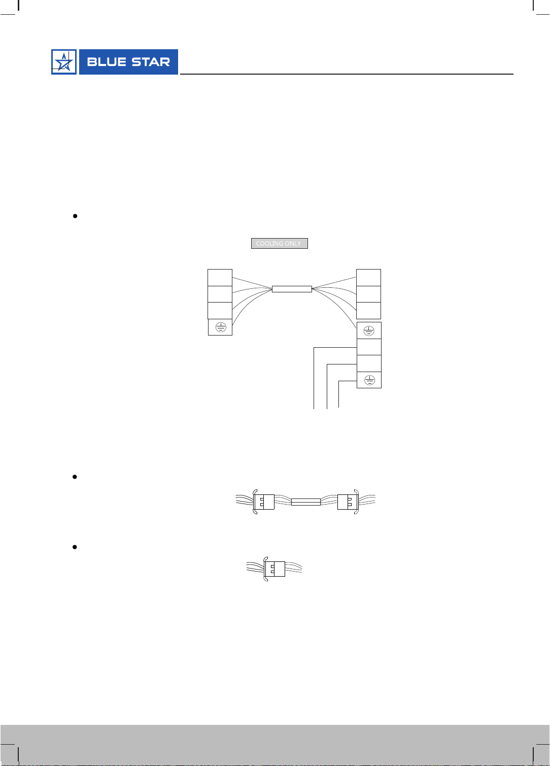
Wiring Diagram
CJRRA & CJYRA - 18k & 24k Model
Indoor unit Outdoor unit
Power connecting cord
Blue Blue
Yellow/Green Yellow/Green
Brown
Terminal
Brown
NN
1L
1L
Terminal
For above models, the power supply are connected from indoor unit.
For these models, the ground wire may be connected to the electric box directly.
Warning: Before obtaining access to terminals, all supply circuits must be disconnected.
Note: All the wires may be different colors. The indicators ‘1L 2L 3L’ may be ‘4 5 6’ or others.
And the terminal may be defferent from the material object.
19
User’sManual
CJYFA - 18k & 24K Model
For above models, the power supply are connected from indoor unit.
For these models, the ground wire may be connected to the electric box directly.
Installation instructions
Ionizer (The ionizer is an optional part)
Ionizer wire (indoor)
Wire (indoor) Sensor(outdoor)
After connection, the wire should be well wrapped with a wrapping tape and the connector
should be put inside the unit.
Overheat protection or high pressure protection cable (it`s an optional part)
After connection, the ionizer will work automatically .
For these models, the power supply are connected from outdoor unit, with a circuit breaker.
Indoor unit Outdoor unit
Terminal Terminal
Power connecting cord
Terminal
Power supply
N
L
1L 1L
N
L
N
L
CDRRA, CDYRA & CDYFA - 30k Model
CDRRA & CDYFA - 36k Model
Black
Yellow/Green
Gray
Brown
Yellow/Green
Black
Brown
Gray
Wiring Diagram
Warning: Before obtaining access to terminals, all supply circuits must be disconnected.
Note: All the wires may be different colors. The indicators ‘1L 2L 3L’ may be ‘4 5 6’ or others.
And the terminal may be defferent from the material object.
20
Hi-Wall Split Air Conditioner
This manual suits for next models
12
Table of contents
Other Blue Star Air Conditioner manuals


Popular Air Conditioner manuals by other brands


York
York E3GE036S01B installation instructions

Mitsubishi Electric
Mitsubishi Electric MUX-19TV - E1 Service manual

Unitary products group
Unitary products group LA120 installation manual

KITANO
KITANO Roka II Series Operation and installation manual

KONVEKTA
KONVEKTA KL40T operating instructions

Costway
Costway EP23995DE user manual