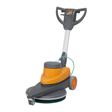
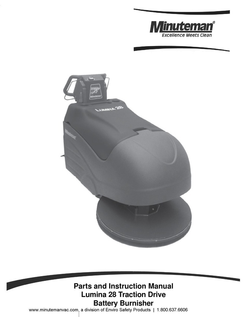
Blue Star 607056 Product manual

604510
Rev. 02 (07-99)
Operator and Parts Manual
20-inch Battery
Burnisher

OPERATION
220-inchBattery Burnisher (07–99)
This manual is furnished with each new model. It
provides necessary operation, machine maintenance
instructions and an illustrated parts list.
Read this manual completely and understand the
machine before operating or servicing.
A complete illustrated Parts Lists is supplied with this
manual, use this list to order parts. Before ordering
parts or supplies, be sure to have your machine model
number and serial number handy. Parts and supplies
may be ordered by phone or mail from any authorized
parts and service center, distributor or from any of the
manufacturer subsidiaries.
This machine will provide excellent service. However,
the best results will be obtained at minimum costs if:
SThe machine is operated with reasonable care.
SThe machine is maintained regularly - per the
machine care instructions provided.
SThe machine is maintained with manufacturer
supplied or equivalent parts.
MACHINE DATA
Pleasefill out at time of installation for future reference.
Model No.-
Install. Date -
Serial No.-
E1999 Printed in U.S.A
TABLE OF CONTENTS
SAFETY PRECAUTIONS 3. . . . . . . . . . . . . . . . . . . . . . .
MACHINE COMPONENTS 4. . . . . . . . . . . . . . . . . . . . . .
MACHINE INSTALLATION 5. . . . . . . . . . . . . . . . . . . . . .
MACHINE UNCRATING 5. . . . . . . . . . . . . . . . . . . . . .
BATTERY INSTALLATION 5. . . . . . . . . . . . . . . . . . . .
MACHINE SETUP 6. . . . . . . . . . . . . . . . . . . . . . . . . . . . . .
PRE–OPERATION CHECKS 6. . . . . . . . . . . . . . . . .
INSTALLING PAD 6. . . . . . . . . . . . . . . . . . . . . . . . . . .
MACHINE OPERATION 7. . . . . . . . . . . . . . . . . . . . . . . . .
WHILE OPERATING MACHINE 8. . . . . . . . . . . . . . .
PAD MOTOR CIRCUIT BREAKER 8. . . . . . . . . . . .
BATTERY CHARGING 8. . . . . . . . . . . . . . . . . . . . . . . . . .
MAINTENANCE 9. . . . . . . . . . . . . . . . . . . . . . . . . . . . . . .
DAILY MAINTENANCE 9. . . . . . . . . . . . . . . . . . . . . .
WEEKLY MAINTENANCE 9. . . . . . . . . . . . . . . . . . . .
MONTHLY MAINTENANCE 9. . . . . . . . . . . . . . . . . .
EVERY 250 HOURS OF OPERATION 9. . . . . . . . .
BATTERY MAINTENANCE 10. . . . . . . . . . . . . . . . .
TRANSPORTING MACHINE 10. . . . . . . . . . . . . . . . . .
STORING MACHINE 10. . . . . . . . . . . . . . . . . . . . . . . . .
RECOMMENDED STOCK ITEMS 10. . . . . . . . . . . . . .
TROUBLE SHOOTING 11. . . . . . . . . . . . . . . . . . . . . . . .
SPECIFICATIONS 11. . . . . . . . . . . . . . . . . . . . . . . . . . . .
PARTS LIST 12. . . . . . . . . . . . . . . . . . . . . . . . . . . . . . . . .
ELECTRICAL DIAGRAM 16. . . . . . . . . . . . . . . . . . . . . .

OPERATION
20-inch Battery Burnisher (07–99) 3
SAFETY PRECAUTIONS
This machine is suited to burnish smooth floors in an
indoor environment and is not constructed for any
other use. Use only recommended pads and cleaning
solutions.
All operators must read, understand and practice the
following safety precautions:
The following safety alert symbols are used throughout
this manual as indicated in their description.
WARNING: To warn of hazards or unsafe
practices which could result in severe personal
injury or death.
FOR SAFETY: To identify actions which must be
followed for safe operation of equipment.
The following information signals potentially dangerous
conditions to the operator or equipment:
FOR SAFETY:
1. Do not operate machine:
– Unless trained and authorized.
– Unless operation manual is read and
understood.
– In flammable or explosive areas unless
designed for use in those areas.
2. Before starting machine:
– Make sure all safety devices are in place
and operate properly.
3. When using machine:
– Go slow on inclines and slippery surfaces.
– Use care when reversing machine.
– Always follow safety and traffic rules.
– Report machine damage or faulty
operation immediately.
4. Before leaving or servicing machine:
– Stop on level surface.
– Turn off machine.
5. When servicing machine:
– Avoid moving parts. Do not wear loose
jackets, shirts, or sleeves.
– Block machine tires before jacking
machine up.
– Use hoist or jack of adequate capacity to
lift machine.
– Disconnect battery connections before
working on machine.
– Wear protective gloves when handling
batteries or battery cables.
– Avoid contact with battery acid.
– Use manufacturer supplied or approved
replacement parts.
WARNING: Batteries emit hydrogen gas.
Explosion or fire can result. Keep sparks and
open flame away. Keep battery compartment open
when charging.
WARNING: Flammable materials or reactive
metals can cause explosion or fire. Do not pick
up.

OPERATION
420-inchBattery Burnisher (07–98)
MACHINE COMPONENTS
4
5 6
3
1
2
7
1. Control Console
2. Control Grips
3. Machine ON/OFF Switch
4. Power ON Indicator Light
5. Battery Level Meter
6. Pad Pressure Meter
7. Circuit Breaker Button
8
9
10 11
12
13
14
16
15
8. Small Rear Wheels
–for tilting back machine to install pad.
9. Pad Pressure Adjustment Knob
10. Wall Rollers
11. Front Caster
12. Pad Guard
13. Battery Hood
14. Battery Hood Latch
15. Pad Driver
16. Main Wheels

OPERATION
20-inchBattery Burnisher (07–99) 5
MACHINE INSTALLATION
MACHINE UNCRATING
Carefully check carton for signs of damage. Report
damages at once to carrier. Batteries and battery
charger are packaged separately.
Battery installation must be accomplished after
removing machine from crate.
To uncrate your machine remove straps and carefully
lift or create a ramp using crate boards to remove
machine from pallet.
ATTENTION: Do not roll machine off pallet,
damage may occur.
BATTERY INSTALLATION
WARNING: Batteries emit hydrogen gases.
explosion or fire can result. Keep sparks and open
flame away. Keep covers open when charging.
FOR SAFETY: When servicing machine, wear
protective gloves when handling batteries or
battery cables. Avoid contact with battery acid.
Recommended Battery Specifications:
Two 12 volt deep cycle 215 amp hour batteries. Part
Number #600394. Maximum battery dimensions are
7in.W (178 mm) x 15.5in.L (394 mm) x 14.25in.H
(362mm).
FOR SAFETY: Before leaving or servicing
machine, stop on level surface and turn off
machine.
1. Be certain ON/OFF switch is turned off.
2. Remove front hood to access battery
compartment. Remove loose battery cable (Fig.1).
Fig. 1.
3. Carefully install batteries into compartment and
arrange battery posts as shown
(Fig. 2).
(+)
(-)
Fig. 2.
ATTENTION: Do not drop batteries into
compartment! Battery and machine housing
damage may result. This damage is not covered
by warranty.
4. Connect cables to battery posts in numerical order
as labeled. RED TO POSITIVE (+) & BLACK TO
NEGATIVE (–) (Fig. 2).
5. Cover cable connections with rubber boots.
Double check cable connections before closing up
battery compartment.
6. Replace hood and secure with latches.

OPERATION
620-inchBattery Burnisher (07–99)
MACHINE SETUP
PRE–OPERATION CHECKS
1. Sweep the floor to remove particles and other
debris.
2. Check battery meter charge level to ensure
batteries are fully charged (See BATTERY
CHARGING).
3. Check that a pad is installed.
4. Before burnishing make sure floor is dry.
INSTALLING PAD
FOR SAFETY: Before leaving or servicing
machine, stop on level surface and turn off
machine.
1. Tilt machine back until it rests on small rear
wheels (Fig. 3).
Fig. 3.
ATTENTION: Do not leave machine tilted back for
an extended time. Battery acid may run out the top
of batteries. Battery acid can cause severe burns
on contact with skin.
2. Remove plastic center pad lock by turning lock
counter–clockwise (Fig. 4).
3. Select a pad that is recommended for 2000 RPM
burnishing. The pad should be a maximum of 25.4
mm (1 inch) thick, 508 mm (20 inch) in diameter
with a standard 89 mm (3.5 inch) center hole.
Machine is not designed for spray buffing.
NOTE: Consult your authorized distributor to assist
you in choosing the correct pad for your specific
burnishing need.
4. Position pad centered on pad driver and replace
centerlock securely (Fig. 4).
Fig. 4.
ATTENTION: Make sure centerlock does not cross
thread or floor damage could occur. Do not over
tighten.
ATTENTION: Do not operate machine without a
pad and the pad centerlock in place.
5. Return machine to operating position immediately.

OPERATION
20-inchBattery Burnisher (07–99) 7
MACHINE OPERATION
FOR SAFETY: Do not operate machine unless
operator manual is read and understood.
1. Adjust pad to correct pad pressure: With pad
installed and caster wheel swung towards pad
driver, rotate pad pressure adjustment knob
clockwise until pad is not touching floor, (check by
manually spinning pad; it should turn freely)
(Fig. 5).
Fig. 5.
2. While manually spinning the pad, increase pad
pressure by rotating knob counter clockwise, until
pad contacts the floor enough to stop the pad.
Then turn knob counterclockwise one more
rotation. This setting will be very close to the
operating setting. Continue through instructions to
achieve exact setting.
3. Activate ON/OFF switch.
4. Twist control grips forward to activate the pad
(Fig. 6).
NOTE: If there is excess vibration realign pad.
FOR SAFETY: When using machine, go slow on
inclines and slippery surfaces.
Fig. 6.
ATTENTION: To prevent floor damage, machine
must be kept moving.
5. Lock pad pressure adjustment knob to correct
pad pressure setting: Turn knob counter clockwise
until pad pressure meter reads in the green zone.
Then lock adjustment knob by turning knurled nut
clockwise (Fig. 7).
Fig. 7.
6. If machine circuit breaker trips, check pad
pressure and/or replace soiled pad. Reset circuit
breaker button after allowing motor to cool (Fig. 8).
See PAD MOTOR CIRCUIT BREAKER

OPERATION
820-inchBattery Burnisher (07–99)
Fig. 8.
7. Begin burnishing by pushing machine forward.
8. Turn ON/OFF switch off when not in use or when
charging.
WHILE OPERATING MACHINE
Periodically check battery meter’s discharge level. When
needle drops to the red zone recharge batteries (See
BATTERY CHARGING).
ATTENTION: Do not continue to run machine when
battery meter needle is in the red zone, battery
damage will result.
FOR SAFETY: Before leaving machine, stop on
level surface and turn off machine.
PAD MOTOR CIRCUIT BREAKER
Machine is equipped with a circuit breaker to protect
pad motor from damage. If the pad motor circuit
breaker trips, it can not be reset immediately.
Determine reason why breaker tripped, allow motor to
cool and then reset. Circuit breaker will trip due to
excessive overload on pad. Clean or change pad if
breaker should trip. Pad motor circuit breaker button is
located at left side of control console.
BATTERY CHARGING
ATTENTION: The following charging instructions
are intended for supplied 24V chargers only.
Otherwise use a charger with the following
specifications to prevent battery damage.
CHARGER SPECIFICATIONS:
SOUTPUT VOLTAGE - 24 VOLTS
SOUTPUT CURRENT - 25 AMPS
SAUTOMATIC SHUTOFF CIRCUIT
SFOR DEEP CYCLE BATTERY CHARGING
NOTE: For optimum machine operation, keep
batteries charged at all times. Never let batteries set in
a discharge condition.
ATTENTION: Do not continue to run machine
when battery meter needle is in the red zone,
battery damage will result.
WARNING: Batteries emit hydrogen gas.
Explosion or fire can result. Keep sparks and
open flame away. Keep covers open when
charging.
FOR SAFETY: When servicing machine, wear
protective gloves when handling batteries or
battery cables. Avoid contact with battery acid.
1. Transport machine to a well ventilated area when
charging.
2. Turn ON/OFF switch off.
3. Remove hood to access battery compartment
(Fig. 9).
Fig. 9.
4. Check water lever ‘‘A”in each battery cell. Do not
charge batteries unless water is slightly covering
battery plates ‘‘B”. If needed, add just enough
distilled water to slightly cover plates. DO NOT
overfill. Batteries can overflow during charging due
to expansion. Replace cell caps before charging
(Fig. 10).

OPERATION
20-inchBattery Burnisher (07–99) 9
A
B
Fig. 10.
5. Plug charger into charger receptacle located near
battery cable connections (Fig. 11).
Fig. 11.
NOTE: Once the charger is connected to the
machine, machine becomes inoperable.
6. Plug charger into grounded wall outlet after
connecting charger to machine (Fig. 12).
GROUNDED
3 HOLE OUTLET
GROUND PIN
Fig. 12.
7. Charger will automatically begin charging and shut
off when fully charged.
8. After charger has turned off, unplug charger from
wall outlet first then disconnect charger from the
machine.
9. Recheck battery fluid level after charging. If
needed, add distilled water to bring level of fluid to
bottom of sight tubes. Be certain to replace cell
caps securely and to wipe off the top of batteries
with a clean cloth.
MAINTENANCE
To keep machine in good working condition, simply
follow machines daily, weekly and monthly
maintenance procedures.
FOR SAFETY: Before leaving or servicing
machine, stop on level surface and turn off
machine.
FOR SAFETY: Before servicing machine,
disconnect battery connections.
DAILY MAINTENANCE
1. Remove and clean pad. Never use soiled pads
when burnishing. Replace pad when it becomes
loaded with residue.
2. Clean machine housing with a nonabrasive,
non-solvent cleaner.
3. Recharge batteries if needed.
WEEKLY MAINTENANCE
1. Check water level in battery cells
(See BATTERY MAINTENANCE).
2. Clean battery tops of corrosion.
3. Check for loose or corroded battery cables.
MONTHLY MAINTENANCE
1. Lubricate axle and caster grease fittings with a
water resistant grease.
2. Check machine for loose nuts and bolts.
EVERY 250 HOURS OF OPERATION
Check pad motor for carbon brush wear, replace
brushes if necessary.

OPERATION
10 20-inchBattery Burnisher (07–99)
BATTERY MAINTENANCE
WARNING: Batteries emit hydrogen gas.
Explosion or fire can result. Keep sparks and
open flame away. Keep battery compartment open
when charging.
FOR SAFETY: When servicing machine, wear
protective gloves when handling batteries or
battery cables. Avoid contact with battery acid.
1. Always follow proper charging instructions (See
CHARGING BATTERIES).
2. Each week AFTER charging, check water level in
each battery cell of all batteries. Water level (A)
should reach bottom of sight tubes (B). If needed,
add just enough distilled water to reach bottom of
sight tubes. DO NOT overfill (Fig. 13).
A
B
Fig. 13.
3. Keep battery tops and terminals clean and dry.
a. Mix a strong solution of baking soda and
water.
b. Brush solution sparingly over battery tops,
terminal and cable connectors.
NOTE: Do not allow baking soda solution to enter
battery cells.
c. Use wire brush to clean terminal post and
cable connections.
d. After cleaning, apply a coating of clear battery
post protectant to terminals and cable
connections.
4. Check for loose or worn cables. Replace if worn.
TRANSPORTING MACHINE
When transporting machine by use of a trailer or truck,
be certain to follow tie–down procedures below:
1. Raise pad with pad pressure adjustment knob.
2. Tilt machine back on small wheels and load
machine using a recommended loading ramp.
ATTENTION: Do not transport machine tilted back
on small rear wheels. Battery acid may run out the
top of batteries. Battery acid can cause severe
burns on contact with skin.
3. Position front of machine up against front of trailer
or truck.
4. Place a block behind the rear wheels and the front
casters.
5. Place tie–down straps over top of machine and
secure straps to floor. It may be necessary to
install some tie-down brackets to the floor of your
trailer or truck.
STORING MACHINE
Remove pad and store machine in a dry area in the
upright position.
ATTENTION: Do not store machine tilted back on
small rear wheels. Battery acid may run out the
top of batteries. Battery acid can cause severe
burns on contact with skin.
RECOMMENDED STOCK ITEMS
Refer to Parts List section for recommended stock
items. Stock Items are clearly identified with a bullet
preceding the parts description. See example below:

OPERATION
20-inchBattery Burnisher (07–99) 11
TROUBLE SHOOTING
PROBLEM CAUSE SOLUTION
No power, nothing runs. Faulty ON/OFF switch Contact Service Center.
Batteries need charging. See Battery Charging
Battery(s) faulty. Replace battery(s)
Loose battery cable. Tighten loose cables.
Batteries are not connected correctly. See Battery Installation.
Pad motor does not run. Faulty roll switch. Contact Service Center.
Machine circuit breaker has tripped. Clean or replace pad and reset
breaker button.
Faulty contactor. Contact Service Center.
Faulty wiring. Contact Service Center.
Faulty pad drive motor. Contact Service Center.
Carbon brushes worn. Contact Service Center.
Short run time. Batteries not fully charged. Charge batteries.
Bad cell in one or more batteries. Replace battery.
Batteries need maintenance. See Battery Maintenance.
Faulty charger. Replace charger.
SPECIFICATIONS
MODEL 20-INCH BATTERY BURNISHER
LENGTH 1320 mm (52 in)
WIDTH 610 mm (24 in)
HEIGHT 940 mm (37 in)
WEIGHT WITH BATTERIES 169 Kg (364 lbs)
PAD DIAMETER 508 mm (20 in)
BRUSH MOTOR 2hp, 2100 rpm brush speed, 24v, 90A, 1500w
BATTERIES 2–215amp/hour, 12v deep cycle
RUN TIME on full charge 3 hours
DECIBEL RATING AT OPERATOR’S EAR, INDOORS ON TILE <70dB(A)

PARTS LIST
20-inchBattery Burnisher (07–98)
12
CHASSIS ASSEMBLY
49
50
42
40
27 29
28
18
23
25
26
24
21
22
19 20
30
41 43 39
44
35
36
37
38
31
32
3353
34 45
52
15
16
17
51
54
56
55
57
58
61
69
60
59
65
66
64 67
48
47
46
10
1112
13
14
32
3
4
6
5
7
8
9
1
3
4
63
68
71
70

PARTS LIST
20-inchBattery Burnisher (07–99) 13
CHASSIS ASSEMBLY
REF PART # DESCRIPTION QTY.
1 602786 CHASSIS, BLACK 1
1 607221 CHASSIS, NAVY BLUE 1
2 25660 AXLE, FRONT 1
3 140015 WASHER, LOCK 2
4 140223 SCREW 2
5 25656 WHEEL 2
6 103071 BEARING 2
7 140013 WASHER, FLAT 2
8 140017 WASHER, LOCK 2
9 2949.5 SCREW 2
10 25666 AXLE, REAR 1
11 4252 WASHER 2
12 4108 DWHEEL, REAR 2
13 14880.5 WASHER, FLAT 2
14 3036.10 SCREW 2
15 25715 STUD 2
16 140506 NUT 8
17 140015 WASHER, LOCK 4
18 140932 LATCH 2
19 140829 SCREW 8
20 140539 NUT 8
21 2728.14 SCREW 1
22 140042 WASHER, LOCK 1
23 25688.BK PANEL, REAR 1
24 120649 DECAL, WARNING 1
25 140018 WASHER, LOCK 4
26 140887 SCREW 4
27 140887 SCREW 1
28 25648 SPRING 1
29 25655 PIN 1
30 25670 TUBE, HANDLE 1
31 25671 BRACKET 1
32 130729 SWITCH 1
33 27098 BRACKET, SWITCH 1
34 27099 BUSHING 1
35 25691.6 SCREW 1
36 6306.4 WASHER 1
DRECOMMENDED STOCK ITEMS
REF PART # DESCRIPTION QTY.
37 15752.14 WASHER, LOCK 1
38 14501 NUT 1
39 200823 DGRIP, HANDLE 2
40 19417 DSWITCH 1
41 130738 DLIGHT, INDICATOR 1
42 25647 DMETER, PAD PRESSURE 1
43 25645 DMETER, BATTERY 1
44 25644 DCIRCUIT BREAKER 70A 1
45 600652 DECAL, DASH 1
46 600394 BATTERY 2
47 600704 CABLE, (NEG) 1
48 600705 CABLE, (POS) 1
49 130367 CABLE, JUMPER 1
50 100706 PLATE, BATTERY 1
51 25726 DECAL, BATTERY CONNECTION 1
52 25646 SHUNT 1
53 15858.12 SCREW 4
54 140552 NUT 2
55 140016 WASHER, LOCK 2
56 140510 NUT 2
57 25642 DCONTACTOR, 24V 1
58 140501 NUT 2
59 6306.4 WASHER 2
60 140889 SCREW 2
61 140042 WASHER, LOCK 2
62 140539 NUT 2
63 140032 WASHER, FLAT 2
64 27833 PLUG 1
65 600736 WIRE (RED) 1
66 600737 WIRE (BLK) 1
67 140019 WASHER, STAR 2
68 2728.12 SCREW 2
69 140540 NUT 2
70 26124 DECAL, CAUTION 1
71 14880.5 WASHER, FLAT 4

PARTS LIST
20-inchBattery Burnisher (07–98)
14
BRUSH DRIVE GROUP
1
2
34
7
6
8
910
12
11
10
1314
13
14
15
169
17
18
19
36
35
37
43
38
39
20
44
45
46 49
47
56
29
48
40
41
42
24
25
2629
25
26
34
15
33
32
21
22
23
50
55 54
52
53
30
31
27
28
51
5

PARTS LIST
20-inchBattery Burnisher (07–98) 15
BRUSH DRIVE GROUP
REF PART # DESCRIPTION QTY.
1 600724 COVER, BATTERY, BLACK 1
1 607223 COVER, BATTERY, NAVY BLUE 1
2 140829 SCREW 4
3 140932 LATCH (ASM.) 2
4 140539 NUT, KEP 4
5 26656.BK GUARD, PAD DRIVER 1
6 25675 DGASKET 2
7 15984 BUSHING 1
8 25674 SCREW 2
9 140045 WASHER, FLAT 1
10 25701 ASM., WIRE 2
11 611221 COVER, RUBBER (BLK) 1
12 611222 COVER, RUBBER (RED) 1
13 140548 NUT, JAM 2
14 140027 WASHER, FLAT 2
15 140015 WASHER, LOCK 1
16 140221 SCREW, HEX 1
17 25652 SPRING 1
18 140594 NUT, HEX 1
19 25672 SPACER, THREADED 1
20 140041 WASHER, FENDER 4
21 140010 WASHER, FLAT 1
22 140016 WASHER, LOCK 1
23 140208 SCREW, HEX 1
24 25650 MOUNT, VIBRATION 1
25 140017 WASHER, LOCK 1
26 2949.5 SCREW 1
27 140047 WASHER, FLAT 1
28 21152 GASKET 1
29 140013 WASHER, FLAT 1
∇Assembly
YIncluded in Assembly
REF PART # DESCRIPTION QTY.
30 130479 DMOTOR, 24V 1
512003 DCARBON BRUSH 4
31 25675 DGASKET 1
32 140628 KEY 1
33 25732 WASHER, FLAT 1
34 140203 SCREW 1
35 240202 DKNOB 1
36 140894 SCREW, SET 1
37 26812 NUT 1
38 26815 NUT 1
39 25683 WASHER, TAPERED 1
40 14880.14 WASHER, FLAT 1
41 26814 SLEEVE 1
42 26811 DCASTER 1
43 606066 DECAL, “IDS”1
43 607082 DECAL, “BLUESTAR”1
44 25679.20 SCREW 2
45 25657 SPACER 2
46 27527 DWHEEL, BUMPER 2
47 4252 WASHER 2
48 140515 NUT, HEX 2
49 140047 WASHER 1
∇50 27073 DASM., PAD DRIVER 1
Y51 27071 DISC, DRIVER 1
Y52 27900 HUB, PAD DRIVER 1
Y53 190177 SCREWS & CAPS SET
Y∇54 25707 ASM., PAD RETAINER 1
Y55 100101 DRING, PAD RETAINER 1
56 600653 DECAL, BRUSH ADJ. 1
D Recommended Stock Items

ELECTRICAL DIAGRAM
16 20-inchBattery Burnisher (07–98)
Table of contents
Other Blue Star Floor Machine manuals
Popular Floor Machine manuals by other brands
Alto
Alto TW 1400 HD operating instructions

Terrco
Terrco 7500 operating instructions
Kunzle & Tasin
Kunzle & Tasin NEW GOLIA PLUS S User & maintenance manual
Schwamborn
Schwamborn ES 51S Translation of the original operation manual

Nobles
Nobles EC-H2O brochure
Kent Euroclean
Kent Euroclean SelectGloss 20B parts list
