Blueair BLMI-300A User manual

Installation and User’s Manual
BLMI-300A
BLMI-500A
BLMI-650A
BLMI-900A
ver.201803_02
I512A-200

23
Table of Contents
Freight Claim Procedure(Important)
1.
Specifications .................................................................................. 4
1.1 Technical Specification
1.2 Product Dimensions
1.3 Accessories Included with the Unit
1.4 How to determine read model names and serial numbers
2. Installation & Operations Guide ................................................. 8
2.1 Location Requirements
2.2 Installation Requirements
2.3 Electrical Requirements
2.4 Installation Checklist
2.5 How to Remove Machine Panel
2.6 Bin Installation
2.7 Bin S/W Installation
2.8 Water supply & Drain Connections
2.9 Wire
2.10 Final Check
2.11 Test Run
3. Operation ........................................................................................ 18
3.1 Button
3.2 Status Light
3.3 7-Segments
3.4 Operation Cycle
3.5 Safety
3.6 Error Codes
4. Maintenance & Cleaning ............................................................. 22
4.1 Maintenance Period
4.2 Interior Cleaning & Sanitizing Procedure
4.2.1 Cleaning Procedure
4.2.2 Sanitizing Procedure
4.2.3 Product Disassembly
4.3 Level sensor Cleaning
4.4 Exterior Cleaning
4.5 Storage Container and Scoop
4.6 Air Filter
4.7 Condenser
4.8 How to Prepare Unit for LongTerm Storage

Freight Claim Procedure(Important)
23
Inspect Immediately
This product has been carefully inspected and packed in accordance with the
carrier’s packing specifications. Responsibility for safe delivery has been
assumed by the carrier. If loss or damage occurs, you as the consignee must file
a claim with the carrier and hold the container for carrier’s inspection.
Visible Loss or Damage
Any external evidence of loss or damage must be fully described and noted on
your freight bill or express receipt and signed by the carrier’s agent.The claim
should be filed on a form available from the carrier.
Concealed Loss or Damage
Concealed loss or damage should be reported to the carrier and vendor within 24
hours af delivery.
After 24 hours the seller is not responsible for any freight damage incurred.
Keep the product as well as all of the original packaging material in a receiving
area for carrier's inspection.
Warning
Connect to potable water supply only.
Adult Supervision is required for safe use either by children under 8 years of age
or the developmentally disabled.
The warranty does not apply to the following.
Repair or replacement of parts required due to misuse, improper care or storage,
negligence, alteration, use of incompatible supplies or lack of specified maintenance.
Regular maintenance items.
Failures caused by improper or erratic voltages, adverse environmental or water
conditions, improper drainage, interruption in electrical or water supply.
Improper or unauthorized repair.
Any ice machine that has been installed and/or maintained inconsistent with the
instructions provided by Blue Air
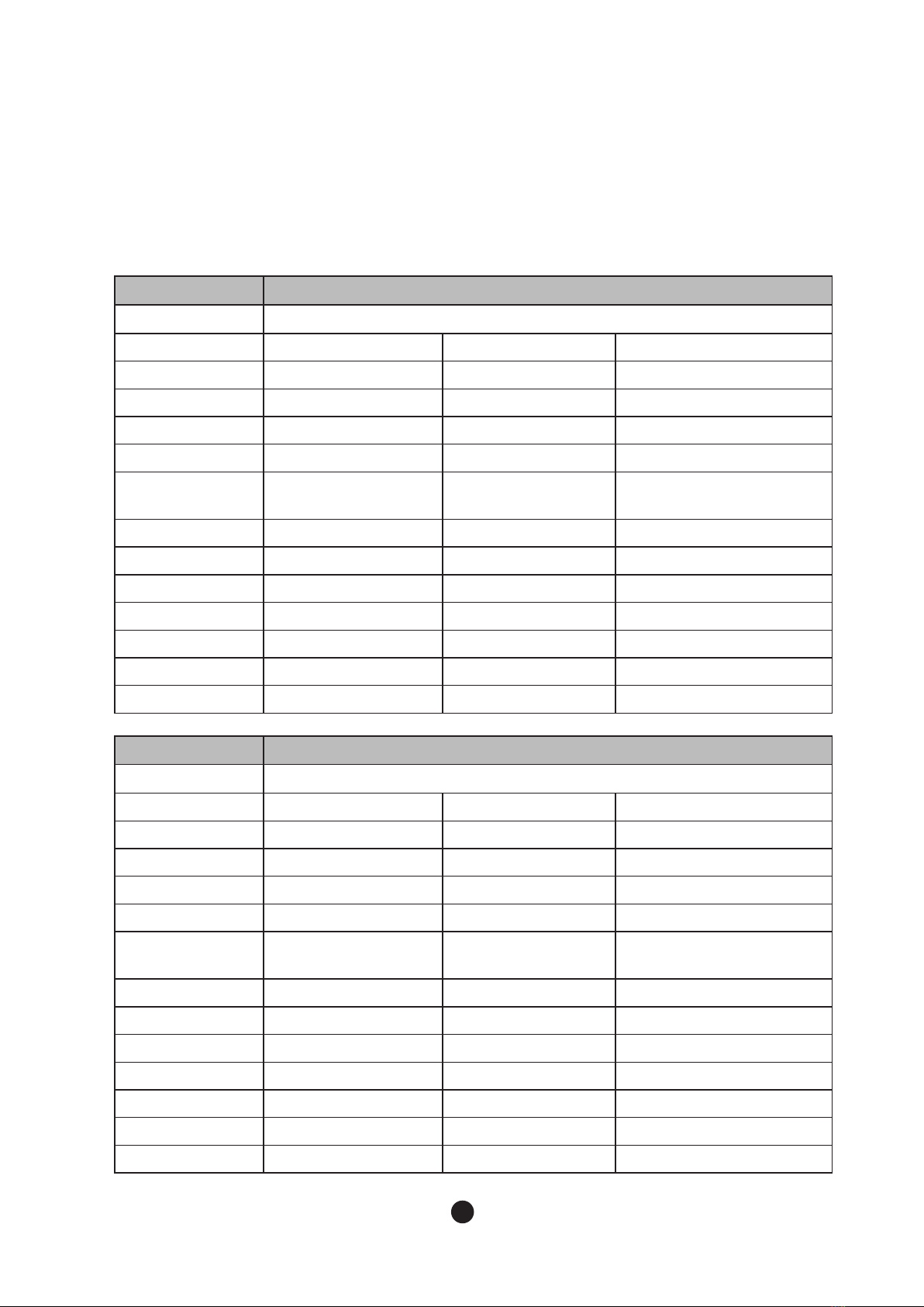
1. Specifications
1.1 Technical Specification
300A
Condenser
Air Cooling
Rated Voltage
115V/60Hz/1Ph 220-240V/50Hz/1Ph
220V/60Hz/1Ph
Rated Ampere
8A 6A
6A
Compressor
115 V 37 LRA 6.35RLA 198-254V 18.6LRA 4.04RLA 187-254V 23.4LRA 4.46RLA
Pump
115V 0.53FLA 59.9W 220-230V 0.16FLA 35.9W 220-230V 0.2FLA 41.3W
Fan
115V 0.68FLA 75.2W 220-230V 0.16FLA 35.9W 220-230V 0.29FLA 62.2W
Maximum Breaking
Capacity of Fuse Size
15A -
-
Designed Pressure
HI –580 / LO –320 psig HI – 380 / LO – 195psig
HI – 380 / LO – 195psig
Refrigerant
R-410A 400g (14.1OZ) R-404A 450g (15.8OZ)
R-404A 650g (22.9OZ)
Safety Approval
UL N/A
N/A
Sanitation Approval
ETL N/A
N/A
Energy Star
Certified N/A
N/A
CE
N/A Certified
N/A
KC
N/A N/A
Certified
500A
Condenser
Air Cooling
Rated Voltage
115V/60Hz/1Ph 220-240V/50Hz/1Ph
220V/60Hz/1Ph
Rated Ampere
14A 7A
7A
Compressor
115 V 57 LRA 11.4RLA 198-254V 18.6LRA 4.04RLA 198-254V 30.0LRA 4.35 RLA
Pump
115V 0.53FLA 59.9W 220-230V 0.16FLA 35.9W 220-230V 0.2FLA 41.3W
Fan
115V 0.68FLA 75.2W 220-230V 0.33FLA 56.9W 220-230V 0.29FLA 62.2W
Maximum Breaking
Capacity of Fuse Size
25A -
-
Designed Pressure
HI – 580 / LO –320 psig HI – 380 / LO – 195psig
HI – 380 / LO – 195psig
Refrigerant
R-410A 450g (15.8OZ) R-404A 650g (22.9OZ)
R-404A 600g (21.1OZ)
Safety Approval
UL N/A
N/A
Sanitation Approval
ETL N/A
N/A
Energy Star
Certified N/A
N/A
CE
N/A Certified
N/A
KC
N/A N/A
Certified
45
● Electrical & Refrigerant Data
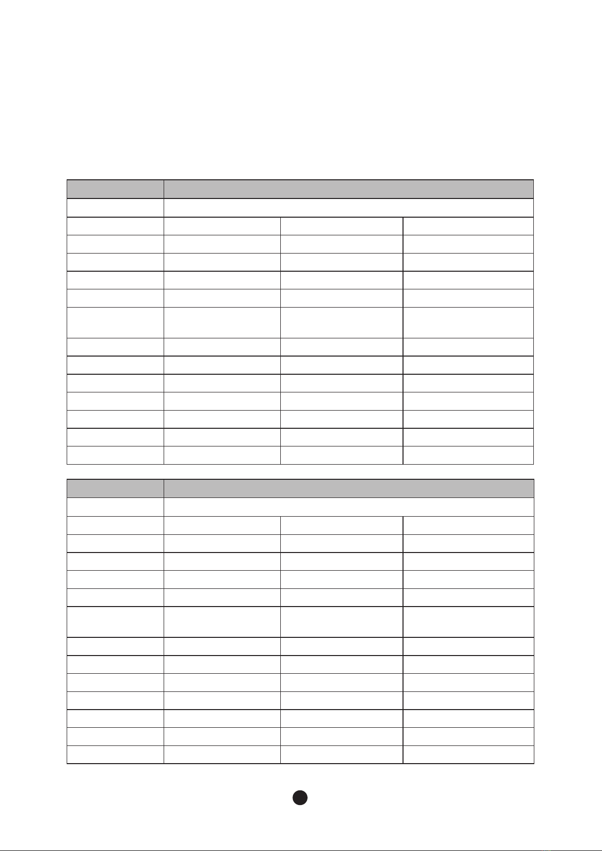
650A
Condenser
Air Cooling
Rated Voltage
208-230V60Hz/1Ph 220-240V/50Hz/1Ph
220V/60Hz/1Ph
Rated Ampere
9A 6A
6A
Compressor
208~230 V 29LRA 6.8 RLA 198 ~ 264 V 24 LRA 5.9RLA 208~230 V 29LRA 5.6 RLA
Pump
115V 0.55FLA 63.5W 230V/50Hz 0.29FLA 61.7W 220V/60Hz 0.28FLA 61.0W
Fan
115V 0.68FLA 75.2W 220-230V 0.33FLA 56.9W 220-230V 0.29FLA 62.2W
Maximum Breaking
Capacity of Fuse Size
15A -
-
Designed Pressure
HI –580 / LO –320 psig HI –580 / LO –320 psig
HI –580 / LO –320 psig
Refrigerant
R-410A 700g (24.6OZ) R-410A 700g (24.6OZ)
R-410A 700g (24.6OZ)
Safety Approval
UL N/A
N/A
Sanitation Approval
ETL N/A
N/A
Energy Star
Certified N/A
N/A
CE
N/A
Certified N/A
KC
N/A N/A
Certified
900A
Condenser
Air Cooling
Rated Voltage
208-230V/60Hz/1Ph 220-240V/50Hz/1Ph
220V/60Hz/1Ph
Rated Ampere
9A 9A
9A
Compressor
208~230V 41LRA 7.6RLA
220V 50LRA 9.4 RLA 208 ~ 230 V 48 LRA 8.8RLA
Pump
115V 0.55FLA 63.5W 230V/50Hz 0.29FLA 61.7W 220V/60Hz 0.28FLA 61.0W
Fan
115V 0.68FLA 75.2W 220-230V 0.33FLA 56.9W 220-230V 0.29FLA 62.2W
Maximum Breaking
Capacity of Fuse Size
15A -
-
Designed Pressure
HI –580 / LO –320 psig HI –580 / LO –320 psig
HI –580 / LO –320 psig
Refrigerant
R-410A 1100g (38.8OZ) R-410A 900g (31.7OZ)
R-410A 1100g (38.8OZ)
Safety Approval
UL N/A
N/A
Sanitation Approval
ETL N/A
N/A
Energy Star
N/A N/A
N/A
CE
N/A
Certified N/A
KC
N/A N/A
Certified
45

No Model Rated Voltage AT 70 °F / WT 50°F
AT 21 °C / WT 10°C
1 300A 115V/60Hz/1Ph 323lbs/day (146 kg/day)
2 300A 220-240V/50Hz/1Ph 303lbs/day (137 kg/day)
3
300A 220V/60Hz/1Ph 337lbs/day (153 kg/day)
4
500A 115V/60Hz/1Ph 517lbs/day (235 kg/day)
5
500A 220-240V/50Hz/1Ph 463lbs/day (210 kg/day)
6
500A 220V/60Hz/1Ph 457lbs/day (208 kg/day)
7
650A 208-230V60Hz/1Ph 625lbs/day (283 kg/day)
8
650A 220-240V/50Hz/1Ph 726lbs/day (329 kg/day)
9
650A 220V/60Hz/1Ph 643lbs/day (292 kg/day)
10
900A 208-230V60Hz/1Ph 890lbs/day (404 kg/day)
11
900A 220-240V/50Hz/1Ph 858lbs/day (389 kg/day)
12
900A 220V/60Hz/1Ph 915lbs/day (415 kg/day)
● Approximate Ice Production
67
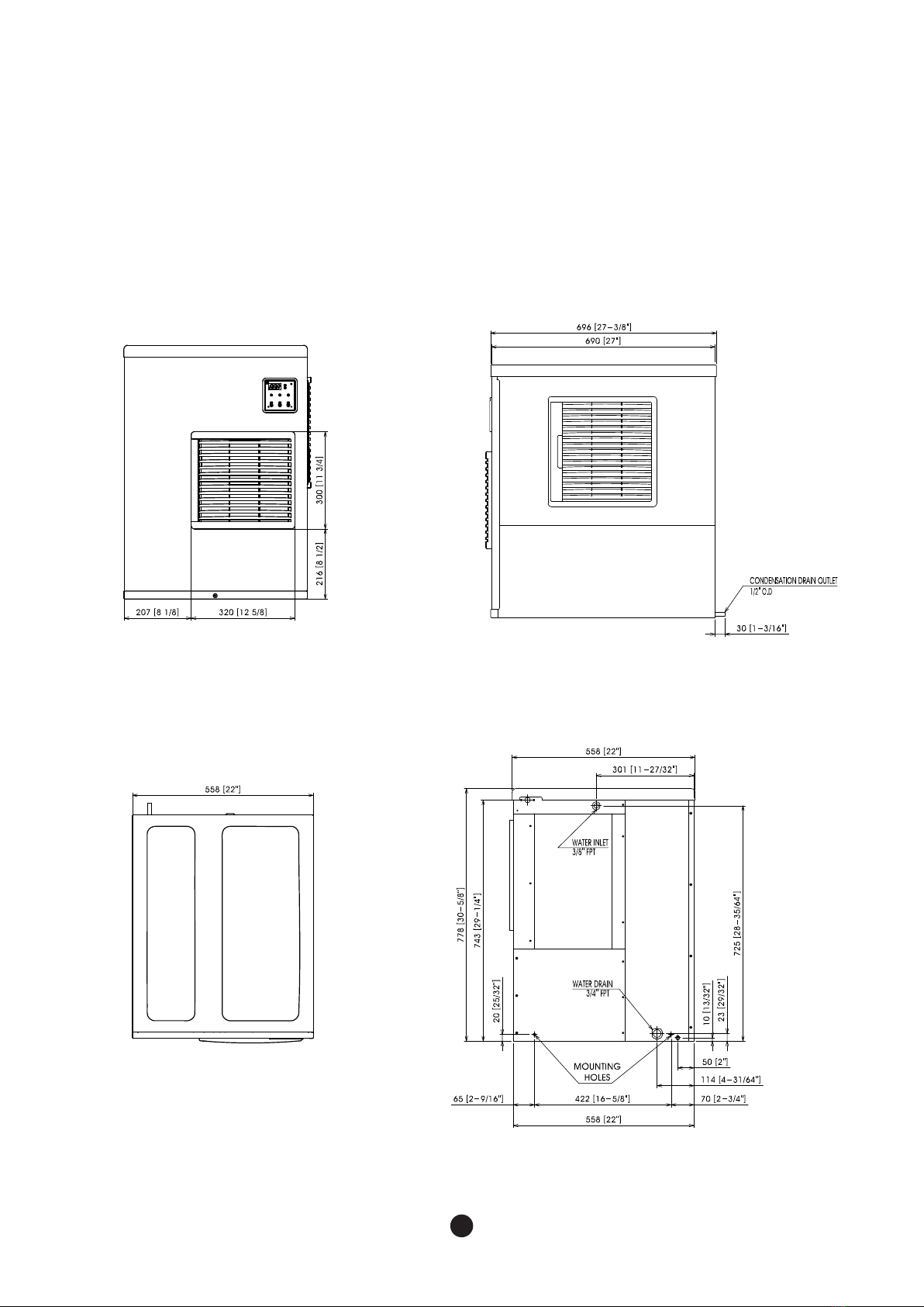
1.2 Product Dimensions
● 300A/500A
67
FRONT
TOP
SIDE
REAR
89
● 650A
FRONT
TOP
SIDE
REAR

89
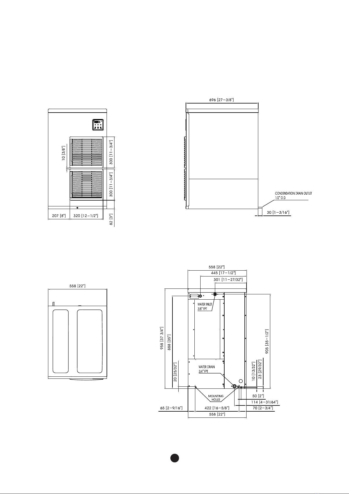
● 900A
FRONT
TOP
SIDE
REAR

10 11
1.3 Accessories Included with the Unit
1.4 How to determine model names and serial numbers
1.4.1 Model names
1.4.2 Serial number
No Name Picture Quantity
1 Bin switch 1
2 M5 Bolt 4
3 Screw M6 2
4 Earth Screw 1
5 User Manual 1
BLMI-900A
daily ice production in pound
a (4 digits) : CIS code for specific model
b (1 digit) : Product group
c (2 digits) : Manufacturing site
(supplier code)
d (1 digit) : Manufacturing year
e (1 digit) : Manufacturing month
f (5 digit) : Serial number (00001 ~ 99999)
BL : Blueair
M : Modular
(U:Undercounter)
I : Crescentice
Air - cooled
a b d e fc
Year 2015 2016 2017 2018 2019 2020
Mark G H J K M N
Month Jan. Feb. Mar. Apr. May. Jun.
Mark 123456
Month Jul. Aug. Sep. Oct. Nov. Dec.
Mark 7 8 9 A B C

10 11
2. Installation & Operation Guide
2.2 Installation Requirements
The installation location of the ice machine should satisfy following conditions.
If the location does not satisfy these conditions, do not install the machines in that location.
The installment location must be changed to meet following conditions.
-The location should be in indoors and have good ventilation
-The location should not be near a heat source and should not be in direct sunlight
-The operating temperature at the location should be between 45°F- 100°F(7°C- 38°C).
-The location should have access to a water supply, drainage and an easily connected
source of electricity
-The location should not have any obstacles, disturbing air circulation(heat exchange)
-The location should have enough clearance for wiring and plumbing on the rear.
-The location should have no food waste nor food contaminant.
-The location should support the full weight of the machine filled with ice.
-The head and bin should be level.
-The vent of the of ice machine and drain of the bin should be separated.
-The drain tip of the bin should have an air gap.
-The ice machine and bin should be completely cleaned after installation.
-The drain line should be easily separated from the ice machine.
-There must be minimum of (8 inches (20 cm) )of clearance, around, above and below the
machine for enough air circulation and maintenance.
- Carefully align the ice machine with the bin to ensure a secure seal.
WARNING
-
The ice machine should be installed, following the local regulations of the country, state and region.
- Read the manual thoroughly before installation. Incorrect installation may cause
malfunction, or bodily injury and death.
- Do not drop tools into the bin or the floor of the unit during installation. It may cause
injure during routine operation of the machine.
- Do not operate unit with enclosure removed.This is marked by a sticker labelled "CAUTION
or WARNING - Parts. Do Not Operate Unit With Enclosure Removed."
(When disassembly for cleaning or similar servicing exposes moving parts.)
2.1 Location Requirements
12 13
2.3 Electrical Requirements
WARNING
- Electrical wiring and grounding of the unit should be done in accordance to the applicable
local, state and federallaws and regulations.
-The ice machine must be grounded in accordance to the law and regulations of the country,
state, and region.
Please read the following warnings
-The Ice machine must be grounded.
-The Ice machine must be connected to an exchangeable fuse or circuit breaker.
- Decide the appropriate size of the wire based on the length, thickness, and position of the wires.
- Electrical wiring and ground must be done by a qualified electrician.
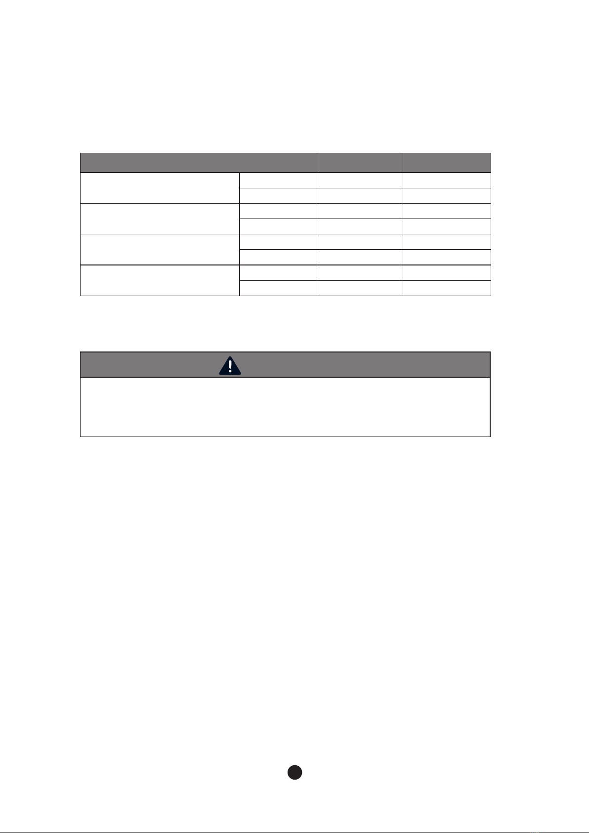
● Installation condition
Condition Minimum Maximum
Ambient Temperature
°F
45 100
°C
7 38
Water temperature
°F
45 90
°C
7 32
Water pressure psig 30 100
kPa 206.8 689.4
Voltage
115V
100 130
220V
208 230
2.3.1 Voltage
2.3.2 Fuse / Circuit Breaker
- When operating the ice machine (with maximized electrical load) range of variation in maximum
voltage allowed is ±10% of the rated voltage.
-Main voltage transformer tab switch must be set to the same input voltage for single phase models,
BLMI-650, 900A.
-The ice machine must be wired to an exclusive fuse/circuit breaker
-The circuit breaker must be installed in accordance with applicable local, state and federal regulations.

12 13
2.4 Checklist before Installation
- After unpacking, please check the product appearance. If there is damage to the product,
contact your place of purchase.
- Remove packing box, tape and other packing components. If these things are not
removed, the ice machine may not function properly.
- Check the name plate for minimum electrical requirement for operating the machine.
Ensure there is sufficient electricity to operate the machine.
-To avoid any damage during installation, remove all panels.
Please refer to “2.5 How to Remove Panel”.
- Remove all accessories, enclosed with the ice machine.
- Remove protective plastic film on the panel.
- Check whether a compressor is secure and the fan blade turns freely.
-The ice machinemustbe installed onto the bin.The available binsare as below.
● LB-300S: 30 inch(762mm)
● LB-220S: 22 inch(558mm)
● For further information, contact the seller.
2.3.3 Power Connection
- Permanently connect : Wiring must be greater than 12AWG.
- Cord connection: Refer to “1.1Technical Specification” to check detailsof cable size requirements
for the power supply.
14 15
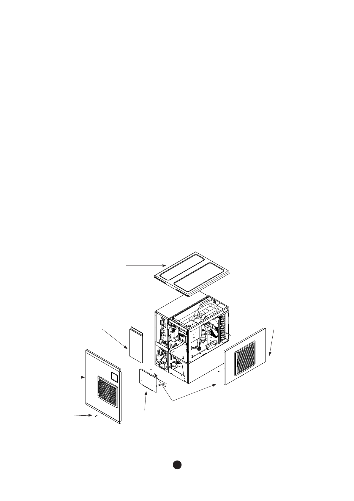
Fig 1
Top panel
Insulation
panel
Screw
Screw
Ice Cover
Side
Panel(R)
Front
panel
2.5 How to Remove Panel
To avoid any damage during installation, please remove all panels.
Please remove them in the following order by referring to Fig 1.
1. Unscrew the bottom screw of the front panel and store it securely.
2. Remove the front panel by firmly grasping the bottom edge and pulling it up and away
from the unit.
3. Store the front panel securely.
4. Remove the top panel by firmly grasping the front edge and pushing back.
5. Store the top panel securely.
6. Unscrew the Side Panel(R), and store it away securely.
7. Grasp the front of the right panel and pull it forward.
8. Store the right panel securely.
9.The left and back panels cannot be removed.
10. Remove the insulation panel by pushing it up.
11. Unscrew the ice cover and remove the cover by pushing it up.
14 15
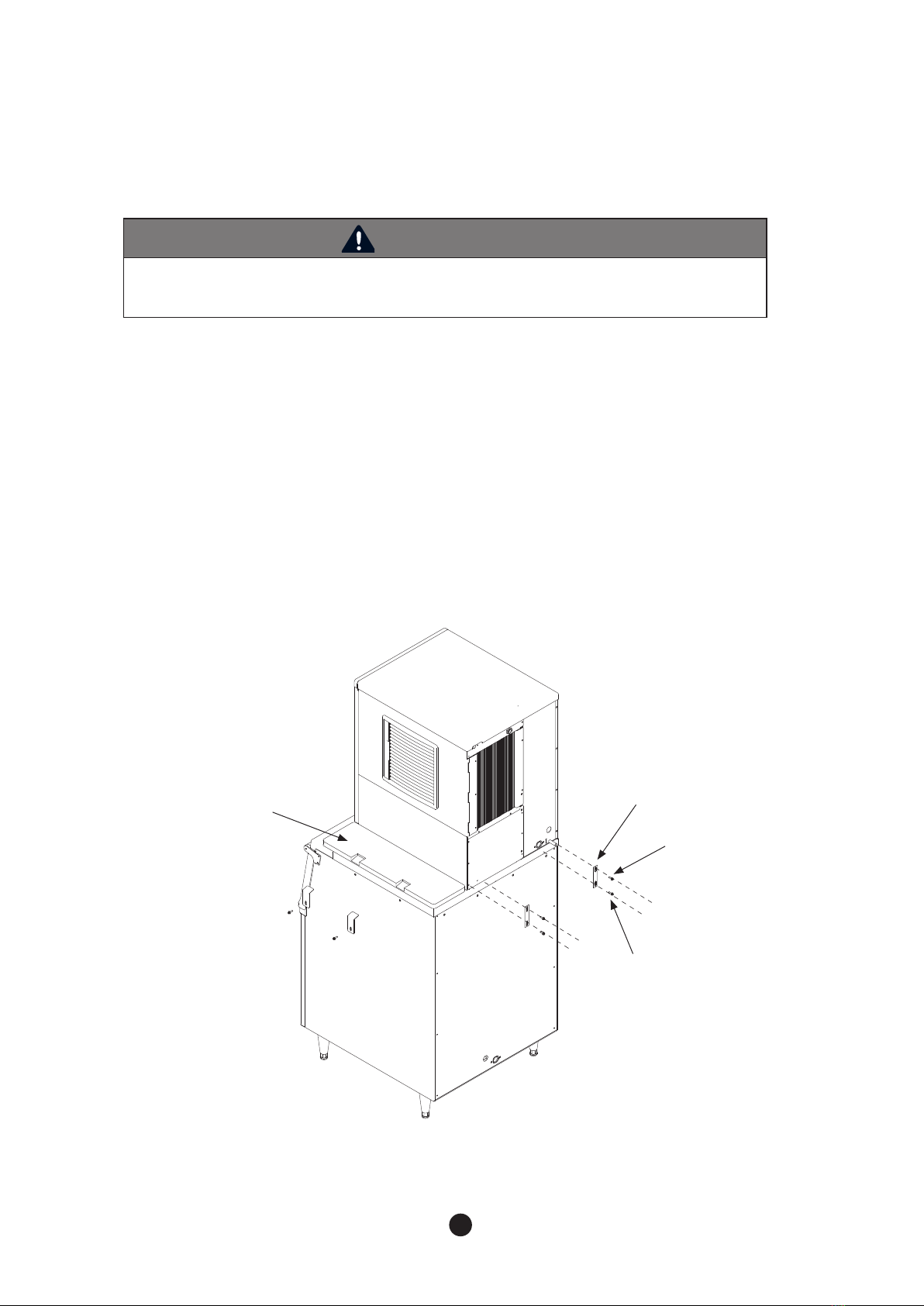
Install the bin in the following order by referring to Fig 2.
1. Position the ice storage bin in the the installation location.
2. If needed, aTOP KIT will need to be installed. For further information, please contact the seller.
3. Ensure the bin is level by adjusting the legs on the bin.
4. Attach the ice machine head onto the bin.
5. Attach the ice machine head to the bin at two points on the back with the enclosed
brackets and screws.
2.6 Bin Installation
WARNING
- Please check whether the ice machine and ice storage bin are compatible before installation.
The ice machine and bin should be properly attached together.
Fig 2
MODUALR
BRACKET
SCREW(M6)
TOP KIT
SCREW(M5)
16 17
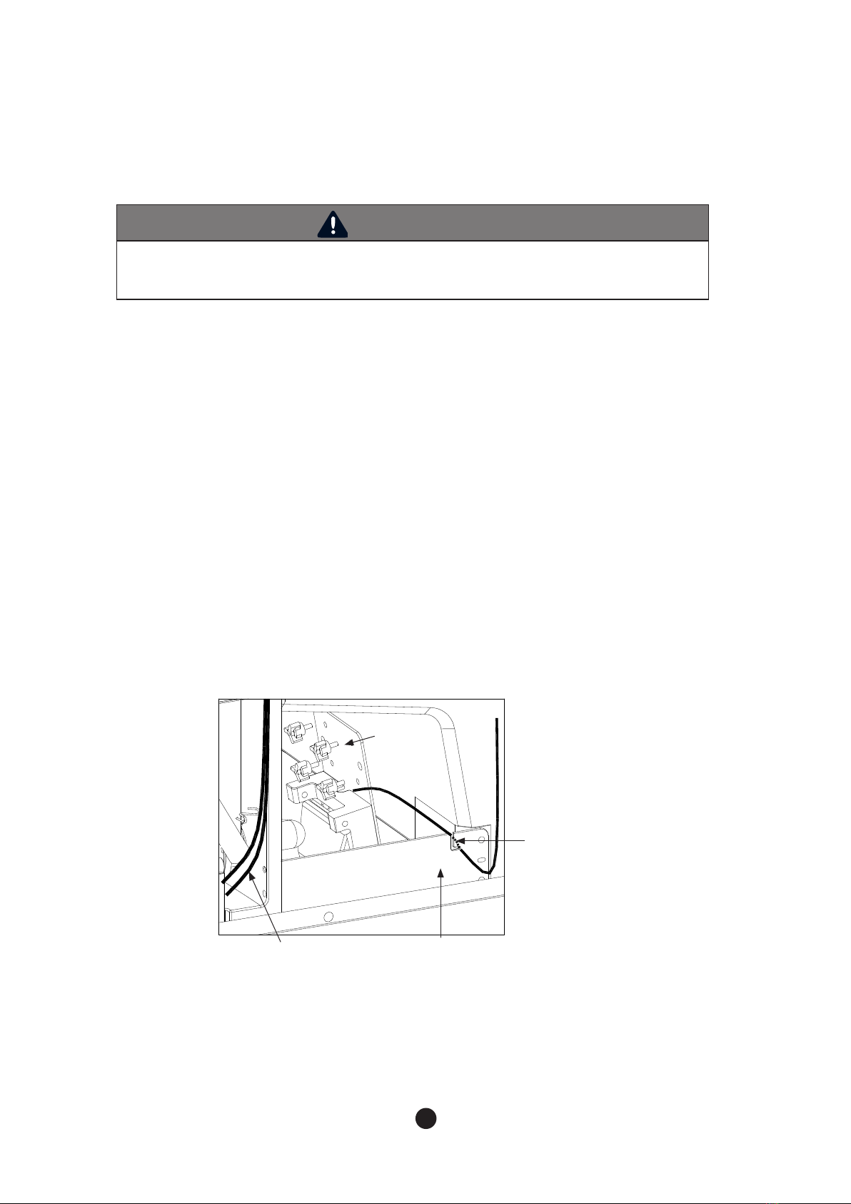
Install bin switch in the following order by referring to Fig 3.
1. When the front panel is removed, enclosed within the machine will be a bin switch,
packed in a plastic.
2.To remove the front panel, refer to “2.5 How to Remove Panel”.
3. Affix the bin switch to the right bottom of the ice machine with fourthumbscrews,
enclosed withthe switch.
4. Position the cable of bin switch into the“J”-type slot of the front supporter by releasing it.
While installing the cable ensure it is not blocking any ice are dropping into the bin.
5. After affixing the cable alongside the Pump motor harness connect it to the blue connector at
the top frame.
2.7 Bin Switch Installation
WARNING
- Bin switch should be equipped before operating the ice machine.
If it is not properly equipped, it might cause a breakdown or malfunction during ice storage.
Fig 3
Thumbscrew
“J” Slot
Supporter frontPump motor
harness

16 17
2.8.1 Water Supply
-Depending on the location where the ice machine is installed, the machineit may
require a water filtration system to prevent formation of scale and removing impurities and
chlorine from the water supply.
2.8.2 Water Supply Line
Refer to the following instructions for installing the water supply line.
- Do not connect a hot water system to the ice machine.
- Water pressure must be between 30 ~ 100 psig(206.8-689.4kPa).
- Water supply line must have a shut off valve.
- Water supply line must be insulated to prevent condensation.
2.8.3 Drainage Line
To prevent backflow of the ice machine and storage container, please refer to the following
instructions for install a drainage line.
- For adequate drainage, a gradient of 1 inch for every 3.3 feet(2.5cm per meter) is needed.
- Do not install any trap.
- Do not connect drainage pipe directly into the sewage pipe.
-There must be a minimum of a 2 inch (50cm)air gap vertically between end of the drainage
pipe and the drain hole.
- Must install a vent.
- Do not combine drain lines for the machine head and the ice storage bin.
-The machine applies gravity drains and does not prevent counter-flow. If you want parts for preventing it,
they must be purchased separately.
2.8 Water Supply & Drain Connections
WARNING
- Installation of water supply and pipe system must be done in accordance to
local, state and federal laws and regulations.
-The ice machine is to be installed with adequate backflow protection to comply
with applicable local, state and federal laws and regulations.
- Water pipe work must be done by a qualified service technicians.

18 19
Fig 7
* Leave a 2”(50mm) vertical air gap between the end of each pipe and the drain
Fig 4
● Conditions for water supply and drainage
Location Water
temperature
Water
pressure
connecting
fitting size
Size of
connecting hose
Water inlet 7°C (45°F) Min.
32°C(90°F) Max.
30 psig(206.9kPa) Min.
100 psig(689.4kPa) Max. 3/8” FPT ID 1/4” copper pipe(Min.)
Drain - - 3/4” FPT ID
3/4” Hard
pipe(Min.)

18 19
-The machine requires an independent power supply. Check the nameplate for proper
voltage and breaker/fuse size.
- Improper electrical supply may cause fuse cutout, damage to cords/wiring or parts, or fire.
-The machine should be properly grounded. Otherwise, there is the possibility to cause injury or death.
- Wiring must be done by a licensed electrician.
- Allowable voltage range is ±10% of standard voltage.
- Do not use extension cords.
-Touching the control box with a wet hand might cause an electric shock.
- Do not use broken power cords. Do not tie nor convert power cords.
- Do not pull out power cords recklessly or lay heavy objects on them.
Always pull out power cords, by firmly grasping the plug.
- Power connection should be at least 7/8" diameter, and have a 1/2" screw size conduit.
(Permanently connect)
-The green ground wire in the factory-installed power cord is connected to a screw on the bracket where the
cord enters the machine. If it becomes necessary to remove or replace the power cord, be sure to connect
the power cord's ground wire to this screw upon reattachment. (Cord connection)
- In case a power cord is broken, its manufacturer, distributor or a qualified person should replace it for
safety reason. Do not operate a unit with a broken power cord.
2.9 Wire
WARNING
- Wiring must meet the local, state and federal standards where the machine is installed
Improper wiring might cause electric shock, injury, fire or death.
- Wiring must be done by a licensed electrician.
Fig 5
11 5 V
208~230V
220V
RED
220V
REDRED
BLACK BLACK
● 300/ 500
● 650 / 900
20 21
2.11 Test Run
WARNING
The Ice machine is factory-adjusted. In general, no additional setting is required after installing the
product. In cases of random modification, it may cause adverse influence on safety, function,
component lifespan, and warranty period.
WARNING
After installation, make sure that all components, fixture, and thumbscrews are securely
connected Ensure that no impurities have fallen into the ice storage bin.
1. Open shut-off valve of water-supply line.
2.Turn on the ice machine by pushing “POWER” button and operate it for 10 minutes.
3.Turn off the power and remove the front panel.
4. Drain the remaining water inside of the tank after removing Ice cover and disconnecting the ‘ㄷ’ shape hose
that connects the Water tank and Pump motor.
5. After drainage, reattach hose.
6. With a neutral detergent, clean the inside of the ice storage bin.
7. Re-assemble ice cover and the front panel.
8.Turn on the ice machine again.
9. Check if the bin switch works by pushing flap of the bin switch within first 5 minutes of freezing cycle.
10. Continue Pressing flap of the bin switch for 10 seconds.
11. The ice machine will stop operation with ‘Full’ display. After 5 seconds you should stop pressing the flap of
the bin switch, ‘Full’ will be disappeared and the ice machine goes into the water supply procedure. (The ice
machine will stop operation immediately if you press flap for 10 seconds within 5 minutes after initiating
ice making cycle. If not, the ice machine will stop after completion of ice making and harvest cycle.)
(1) Is ambient temperature of the installation area within the appropriate temperature range of
45-100°F(7-37°C)?
(2) Is water temperature supplied to the installation area within the appropriate temperature range of 45-90°F
(7-32°C)?
(3) Are all the packing materials such as the packing box, inside tape, and other materials removed
completely?
(4) Is there enoughclearance (min. 8 inches)above, below and around the ice machine for smooth air
circulation?
(5) Is the ice scoop placed in the right place?
(6) Is the ice machine level on the floor?
(7) Is the product located indoors?
(8) Is the power supply to the ice machine installed properly?
(9) Is the water supply pipe to the product properly connected?
(10)Is drain system properly connected?
(11)Is water pressure between 30 ~ 100 psig (206.8-689.4 kPa)?
(12)Are there any leakages found in any pipes?
(13)Are all the components, fixtures, and thumbscrews secure?
(14)Have you informed customers about the product manual, how to operate the machine, and when to
replace parts?
(15)Have you informed the customer how to get service if the unit has a problem?
2.10 Final Check
Other manuals for BLMI-300A
2
This manual suits for next models
3
Table of contents
Other Blueair Ice Maker manuals


 Service manual")


