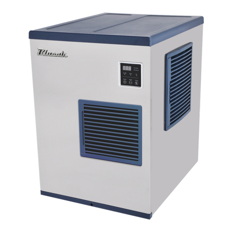
Blueair BLMI-500AD User manual

SERVICE MANUAL
BLMI-500AD
VER200626

Contents
1General information
1.1 For your safety
1.2 Warranty
1.3 How to read model names and serial numbers
1.4 Installation
1.5 Water supply and drain pipe connection
1.6 Assembly structure
1.7 Specifications
2Technical information
2.1 Water and refrigeration system
2.2 Operation
2.3 Control board
3Troubleshooting
3.1 Parts operation check
3.2 How to update main control board program
3.3 Error codes
3.4 Problems and resolutions
4Circuit diagrams and technical data
4.1 Circuit diagrams
4.2 Performance data
4.3 Evaporator sensor data

1General information
1.1 For your safety
WARNING
-The ice machine must be installed in accordance with individual State/Regional Codes and
regulations.
-Read the manual thoroughly before installation. Improper installation may void or limit warranty
coverage. Most Importantly, Improper installation may damage the unit and could cause
serious injury.
-The ice machines must be installed and serviced by a licensed and qualified technician.
-The ice machine must be grounded and have an independent electric supply.
The ice machine must be leveled and the front edge of modular head and storage bin must be
flat.
-Water Supply to the ice machine must be potable and of food grade
-High pressure refrigerant is charged into the ice machine. Be careful not to damage the
refrigerant circuit during installation, maintenance, and service.
-Remove remaining water on the bottom side of the ice machine and any other things may
cause danger before installation, maintenance, and service.
-Turn off the power and disconnect electrical connection before installation, maintenance, and
service.
-Wear full protective clothing when using chemicals for maintenance.
-Do not remove the ice by using sharp tools such as a knife. This prevents damage to the
evaporator.
1.2 Warranty
WARNING
-Defective or non-approved parts obtained by unauthorized parties that cause damage to the
machine will void warranty.
Warranty Period
Parts & Labor
3 years
Compressor
5 years
Evaporator
5 years

1.3 How to read model names and serial numbers
Year
2015
2016
2017
2018
2019
2020
Mark
G
H
J
K
M
N
Month
Jan.
Feb.
Mar.
Apr.
May.
Jun.
Mark
1
2
3
4
5
6
Month
Jul.
Aug.
Sep.
Oct.
Nov.
Dec.
Mark
7
8
9
A
B
C
a (4 digits) : CIS code for specific model
b (1 digit) : Product group
c (2 digits) : Manufacturing site (supplier
code)
d (1 digit) : Manufacturing year
e (1 digit) : Manufacturing month
f (5 digits) : Serial number (00001 ~ 99999)
BLMI-500AD
B: Blue Air (on US model # only)
L: Lassele (Our brand in S. Korea)
M-Modular or U-Undercounter
I: Crescent shaped ice
Daily ice Production in LBS.
A: Air-cooled
W: Water-cooled
D: Dispenser

1.4Installation
1.4.1 Suggested Installation requirements
-Indoors with good ventilation.
-No heaters or hot side equipment around the machine. Do not place in direct sunlight..
-Absolutely requires a sufficient water supply, well equipped drainage system, and close proximity to
power outlet.
-Ice machine should not have any obstructions near the machine to promote and maintain proper air
flow and optimum ice production.
1.4.2 Installation check list
-Are the front edges of modular head and ice storage bin level and in alignment?
-Is the air vent pipe for the machine and drain line for ice storage bin separated?
-Is there an air gap at the end of the drain pipe of the ice storage bin?
-Have the modular head and ice storage bin, been checked and cleaned after installation?
-Is the drain pipe easily disconnected from the modular head?
-Is there 8”(200mm) minimum clearance around the ice machine?
1.4.3 Required environmental condition
Contents
Model
Available Range
Ambient
Temperature
All
7-38℃
45-100℉
Water
Temperature
All
7-32℃
45-90℉
Water
Pressure
All
30-100psig
2-7kg/㎠
Voltage
115V
104-127V
208-230V
187-264V
220-240V
198-254V

1.5 Water supply and drain pipe connection
There must be at minimum of 2”(50mm) vertical clearance between
drainage pipe end and drainage hole.
Drain outlet
-3/4”FPT
Shut-Off valve
valve CCVVCD
Copper pipe
- Minimum ID 1/4”
Drain valve
Vent tube
Hard pipe
- Minimum ID 3/4”
“
Bin drain outlet-
3/4”FPT
Water supply inlet
-3/8”FPT
Floor drain

1.6Assembly structure
1) BLMI-500AD
Evaporator
Spray Tubes
Water inlet Valve
Cleaning Valve
Level Sensor
Water Pump
Control box
Water Valve
Compressor
Drier
Fan Motor
Condenser
Hot gas Valve
Bin control
Drain Valve

1.7Specification
Content
500AD
REMARKS
AC Supply voltage
115V/60Hz
Amperage &
power consumption
14A /1100W
AT90℉/WT70
℉
AT32℃
/WT21℃
Maximum Fuse
Circuit Breaker
15A
Product size (W*D*H)
30" * 24" * 20" [inch]
762 * 610 * 560 [mm]
Weight
126 lbs. (57 kg)
Per Cycle
( lb / Cubes)
9.18 lbs. (4.16 kg) / 432 Cubes
-
Refrigerant
R-410A

2Technical information
2.1 Water and refrigerant system
Refrigerant Circuit
Water Circuit
Comp
essor
Water
Pump
Spray Tube
Level
Sensor
Evaporator
Supply Tube
Overflow
Hot gas
V/V
Exp
V/V
Water
V/V
Fan
Motor
V/V
Water inlet
V/V
Cleaning V/V
Drain V/V

2.2 Operation
1) During freezing and harvesting cycle
WATER FILL CYCLE
HARVEST CYCLE(
FREEZE CYCLE
DRAIN
CYCLE
LS check
Thermistor in control
Timer in control
5 min
FS in control
Timer
Comp On
HGV On
LV Off
FM Off
PM Off
WV On
WV On
HGV On
THRMISTOR
7℃
PM On
Thermistor
1℃reaches
PM 15s Off
Ice Seonsor
in control
Comp On
HGV Off
LV On
FM On
PM On
WV Off
FS Open
LS Open
Comp On
HGV On
LV Off
FM Off
PM Off
DV On
Or
PM On
MAX : 25 min
MAX : 60 min
Comp : Compressor
HGV : Hot Gas Valve
LV : Liquie Valvve
FM : Fan Motor
PM : Pump Motor
WV : Water Valve
LS : Level Sensor
DV : Deain Valve

2) During ice storage bin is full
s
DRAIN CYCLE
Bin Full
WATER FILL
CYCLE
DV Off
Or
PM Off
DV On
Or
PM On
WV On
HGV On
Comp On
HGV On
LV Off
FM Off
PM Off
WV On
LS Close

3) Sequence
⚫Stand-by
-Once the ice machine is connected to the main power suppy, it shows model name
and PCB (control board) version and stand-by for operation.
⚫Water supply
-As soon as the power is turned on, the ice machine will immediately begin the
water supply cycle.
-The ice machine will revert back to the water supply cycle if the machine is reset
(turned off and turned on) during operation.
-The water valve and hot gas valve are operational during the water supply cycle.
-On/off LED light turns to green from red once water supply cycle is complete.
-“XX”is displayed during water supply cycle. [.XX = Elapsed time (x 10 seconds)].
Example: the number 1 before the dot signifies water supply cycle (2 being
harvest cycle and 3 being freezing cycle). .02 means the water has been supplying
the machine for 20 seconds. The last 2 digits tell you the time. Simply multiply
by 10 and you will have the exact number of seconds the water cycle has been
active.
⚫Harvest
-The action of dropping a batch of ice from the evaporator into the bin is called the
“Harvest cycle”
-The ice machine continues to repeat harvest and freezing cycles except for the first
time the machine is turned on.
-The compressor, hot gas valve, and water valve are in operation during the harvest
cycle
-Once evaporator temperature sensor reaches 7℃(44.6℉), harvest will be complete.
This is due to the factory harvest delay time setting. (Default harvest delay time
depends on model).
-The Water pump starts operation before the harvest cycle is done.
-On/off LED light turns from Red to Green once the harvest cycle is complete.

-Harvest LED light turns to Green.
-“2.xx”is displayed during harvest cycle. [.xx = Elapsed time (x 1 minute)]
Example: The display reads: 2.03 during the harvest cycle. The first number (2)
indicates that the ice machine is in the Harvest cycle. The second number (03)
indicates that the machine has been in harvest for 3 minutes.
⚫Freezing
-Freezing cycle is the act of water freezing onto the evaporator plate creating ice.
-Compressor, fan motor, water pump, and water valve are in operation during
freezing cycle
-Once the freeze cycle is complete the LED light turns to Green.
-During the freezing cycle the LED light will be Red.
-“3.xx”is displayed during freezing cycle. [.xx = Elapsed time (x 1 minute)]
Example: The display reads: 3.02 during the Freezing cycle. This first number (3)
tells us the ice machine is in the freezing cycle. The second number (02) tells us
the freezing cycle has been active for 2 minutes.
⚫Drainage
-The ice machine has regular drainage intervals. When the ice bin is full the machine
will drain water regularly from the machine directly following the freezing cycle.
-The drainage interval last from 10-20 seconds.
-Regular drainage time and interval can be adjusted once the water conditions are
ascertained at the site of installation.
-The ice machine will go into the drainage interval if the ice storage bin is full for
five minutes to prevent contamination of water inside the water tank.
⚫Full storage
-If the bin switch senses the bin is full of ice but the ice machine is in the middle of
a new harvest cycle, ice production will cease once the current harvest cycle is
complete. Ice production will also cease if the bin switch senses a full bin five
minutes before a new freezing cycle begins.
-If the bin switch senses that the bin is full five minutes After the freezing cycle
begins all ice production will stop once the very next Harvest cycle is completed.
-If the bin switch senses the bin is not full after consuming some ices, the ice
machine resumes working from water supply cycle.

2.3 Control board
2.3.1
CN 10
CN 11
RLY 8
RLY 5
RLY 4
RLY 2
L1
BUZ1
EC 2
EC3
D10
EC 1
CN 3
RLY1
CN 6
XC 2
LF 1
XC 1
VA 8
VA 5
VA 2
BD1
CN 13
CN 2
Liquid V/V
Cleaning V/V
Drain V/V
Water Pump(C.C.W)
Water V/V
Fan Motor
Hat Gas V/V
Water Pump(C.W)
Compressor
Power
Bin Sensor
Float Switch
Evaporator Sensor
Control PCB
CN 5
RLY 7
RLY 6
RLY 9
VA 7
VA 6
VA 4
VA 3
RLY 3
VA 9
CN2-1
CN 4
HS1
Transformer

2.32 Display control board
2.3.1.1 Features
⚫7-segment
Display
Meaning
1 = Water supply cycle
.xx = Elapsed time (x 10 seconds)
Ex) 1.02 = In water supply cycle for 20 seconds.
2 = Harvest cycle
.xx = Elapsed time (x 1 minute)
Ex) 2.02 = In harvest cycle for 20 seconds.
3 = Freezing cycle
.xx = Elapsed time (x 1 minute)
Ex) 3.02 = In freezing cycle for 20 seconds.
In drainage cycle.
In cleaning cycle.
Need to add cleaner or sanitizer.
Cleaning cycle is completed.
Status LED lamp
Display
Buttons

⚫Error codes : Below error codes will be displayed so technicians can immediately identify
specific malfunctions.
Display
Meaning
E1
Freezing cycle exceeds 60 minutes twice in a row.
E2
Harvest cycle exceeds 25 minutes twice in a row.
E3
Evaporator sensor temperature is over 60℃(140℉).
E4
Water is not drained during full storage.
E5
Water level sensor continues to detect insufficient water
levels.
E6
Evaporator sensor error. (damaged or disconnected).
E7
Main Control Board
Main PCB program error.
E8
Ambient temperature error.
E9
Bin switch error.
HI
Ambient temperature is over 45℃(113℉).
LO
Ambient temperature is lower than 5℃(41℉).
-E1 : If the freezing cycle exceeds 60 mins for the first time, the ice machine will
activate the harvest cycle. This is called a “forced” harvest. E1 will be displayed if
the same situation happens again.
-E2 : If the harvest cycle exceeds 25 mins for the first time, the ice machine will
activate the freezing cycle. This is called a “forced” freezing cycle. E2 will be
displayed if the same situation happens again.
-E3 : If evaporator sensor temperature is over 60℃(140℉).
-E4 : The ice machine automactically drains 5 minutes after the bind is full. E4 will be
displayed if the water is not drained for 480 seconds.

-E5 :
1) For the first ice making cycle: If the float switch does not sense enough water at
the end of the first water supply cycle, the ice machine will go back to the water
supply cycle again before advancing to the harvest cycle. E5 will be displayed If
the float switch continues to sense insufficient water levels during subsequent
supply cycles.
2) Beginning with the second ice making cycle: If the float switch does not sense
sufficient water levels at the end of the harvest cycle, the ice machine will return to
the harvest cycle instead of advancing to the freezing cycle. E5 will be displayed If
the float switch continues to sense insufficient water levels during the second
harvest cycle.
-E6 : If the evaporator sensor is either damaged or disconnected.
-E7 : If main PCB is not operating properly.
-E8 : If ambient temperature sensor is damaged
-E9 : If bin switch is either not properly assembled or disconnected
-“HI”will be displayed if ambient temperature is over 45℃(113℉).
-“LO”will be displayed if ambient temperature is lower than 5℃(41℉).
⚫Status LED lamp
LED
Color
Meaning
On/Off
Green
Water has been supplied.
Red
Water has not been supplied yet.
Orange
Ice storage bin is full.
Freeze
Green
In freezing cycle.
Harvest
Green
In harvest cycle.
Clean
Green
In cleaning cycle.
Err
Red
The ice machine has a problem
⚫Buttons
-Power : To turn the ice machine on or off: Press and hold power button for 2
seconds.

-Wash : For cleaning and sanitizing the ice machine.
-Check : Allows the user to check the status of different operations of the machine.
⚫Combination
-Power + Wash : Pressing and holding these buttons will force the machine into the
harvest cycle.
-Power + Check : Pressing and holding these buttons will force the drainage cycle.
-Wash + Check : This will open the hot gas valve and water valve to aid in the
system evacuation in the lines if necessary.
⚫Status check :
- Once the check button is pressed, the display will cycle through the status of each
of the categories below. Simply press check again to get to the next operation in the
sequence. If there is no further activity on the check button, the display will
automatically return to the standard operation status display.
Sequence
Status
Remarks
1 - E
Evapoator sensor Temeprature
2 - F
Average time of freezing cycle
3 - H
Average time of harvest cycle
4 - 三
Total freezing cycle counts
5 - ###
Ambient temperature

2.3.2 Parameter setting
2.3.2.1 Instruction - How to change the setting
Number
Display
Direction
1
Press check button for 5 seconds to change
parameter setting.
2
P-1 will be displayed.
3
Press check button again to adjust P-1 setting
result.
The setting can be adjusted up or down by
pressing power or wash buttons.
4
P-2 after pressing the check button again, P-2 will
be displayed.
5
-
Refer to following table to check each parameter’s
meaning and further information.
6
Press check button for five seconds to get out of
the parameter setting mode.

2.3.2.2 Parameter code meaning
Number
Display
Features
Range
Adjustable value
1
P-1
Set evaporator temperature for
harvest control
5 ~ 30℃
41 ~ 86℉
1℃, 1℉
2
P-2
HI
Set harvest delay time when
ambient temperature is high.
60 ~ 300
sec
5 sec
LO
Set harvest delay time when
ambient temperature is low.
60 ~ 300
sec
5 sec
3
P-3
drainage cycle interval
1 ~ 10
1,2,5,10
4
P-4
Sensor temperature correction
-2 ~ 2℃
-4 ~ 4℉
0.1℃
1℉
5
P-5
Set water pump delay time to
prevent ice from becoming slush.
10~60 sec
1
6
P-6
Set PCB program
25A~90A
7
P-7
Reset freezing cycle count
0~1
1
8
P-8
Set drainage time
10~20 sec
10
9
P-9
Set water supply time during
harvest
0~300 sec
10
10
P-10
Set bin switch error alarm
Y,N
Y,N
Table of contents
Other Blueair Ice Maker manuals
