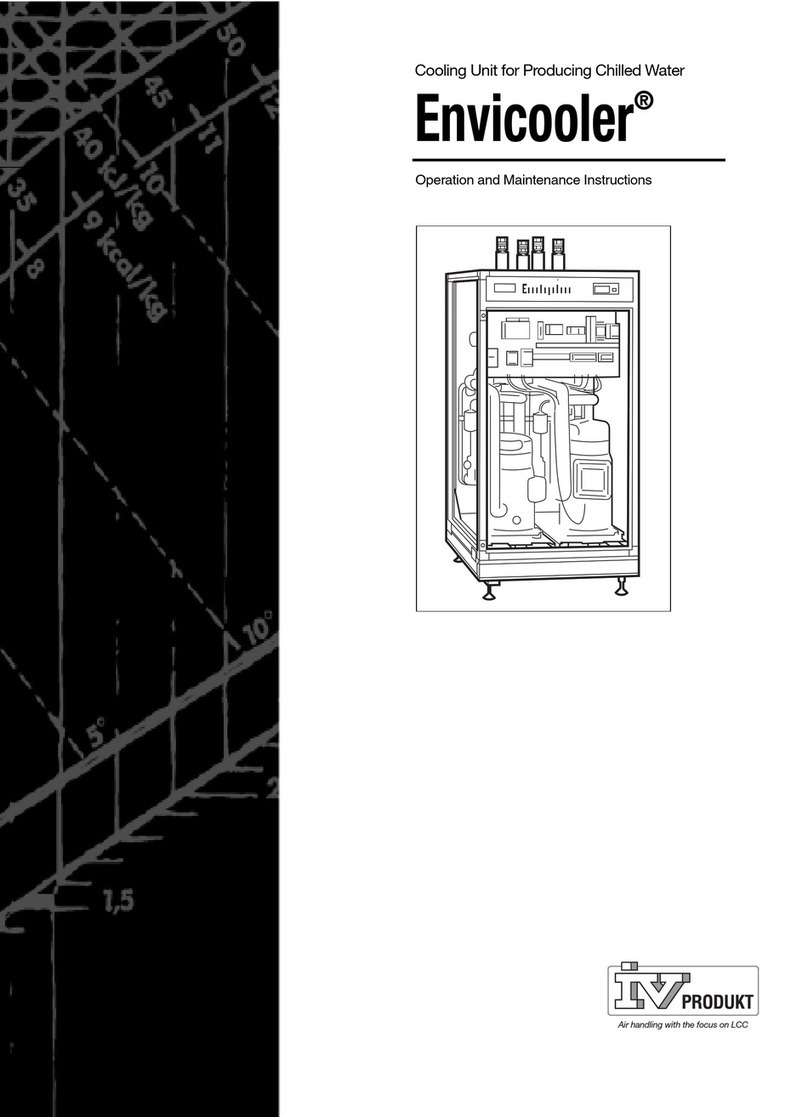
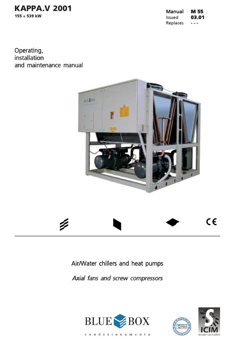
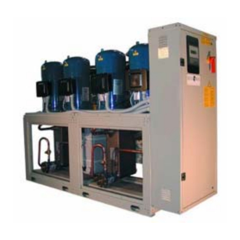
BlueBox ZETA 2002 3,2 Installation guide

Manual 101010B02
Issue 11.02
Replaces 04.02
ZETA 2002
38 - 266 kW
Water chillers Air/water Axial fans and
self-contained scroll compressors
0062
Installation, operating,
and maintenance
manual
ISO 9001 - Cert. n. 0201


Blue Box
CONTENTS Page
ZETA 2002 - water chiller ......................................................................................................... 1
UNIT FRAME ............................................................................................................ 1
COMPRESSORS ........................................................................................................ 1
CONDENSER ............................................................................................................ 1
CONDENSER FANS................................................................................................... 1
EVAPORATOR .......................................................................................................... 1
REFRIGERANT CIRCUIT ............................................................................................. 1
ELECTRICAL PANEL.................................................................................................. 1
CONTROLS AND SAFETY DEVICES............................................................................ 2
TESTING .................................................................................................................. 2
ZETA UNIT VERSIONS .............................................................................................................. 2
ZETA 2002 /HP: reverse cycle heat pump................................................................... 2
ZETA 2002 LE: condensing unit. ................................................................................ 2
ZETA 2002 LE /HP: heat pump condensing unit .......................................................... 2
HYDRAULIC MODULE OPTIONS ............................................................................................... 3
ZETA 2002 /ST 2PS : ZETA 2002 /ST 2PS : unit with storage tank and pumps .............................. 3
ACCESSORY VERSIONS ........................................................................................................... 3
ZETA 2002 /DS: unit with desuperheaters................................................................... 3
ZETA 2002 /LN: low noise unit .................................................................................. 3
ZETA 2002 /SLN: extra low noise unit ........................................................................ 3
REFRIGERANT CIRCUIT ACCESSORIES: ..................................................................................... 4
- Step type condensing pressure contro ...................................................................... 4
- Condensing pressure control by means of fan speed regulator .................................. 4
- Dual set-point ........................................................................................................ 4
- Pressure gauges ..................................................................................................... 4
- Liquid receivers ..................................................................................................... 4
- Compressor suction and discharge valves ................................................................. 4
- Liquid line solenoid valve ........................................................................................ 4
HYDRAULIC CIRCUIT ACCESSORIES......................................................................................... 4
- Leaving water temperature control .......................................................................... 4
- Anti-freeze heater .................................................................................................. 4
- Water side relief valve (version ST only). .................................................................. 4
ELECTRICAL ACCESSORIES...................................................................................................... 4
- Serial interface ....................................................................................................... 4
- Power factor correction cos φ ≥ 0.9.......................................................................... 4
- Single voltage-free contacts for machine status signals .............................................. 4
- Set-point variable ................................................................................................... 4
- Remote user terminal panel .................................................................................... 4
VARIOUS ACCESSORIES........................................................................................................... 5
-Rubberantivibrationmountings ............................................................................... 5
-Spring-typeantivibrationmounts.............................................................................. 5
- Timber packing crate.............................................................................................. 5
- Pallet/skid for shipment in a container...................................................................... 5
- Mesh coil guard with metallic filter .......................................................................... 5
- Anticorrosion treatment of coils for use in aggressive environments ............................ 5
- Non-standard RAL paint colours ............................................................................... 5

Blue Box
SERIES ............................................................................................................................... 6
TECHNICAL DATA - R22........................................................................................... 7
TECHNICAL DATA - ELECTRICAL SPECIFICATIONS AND COMPONENTS R22 .......... 11
TECHNICAL DATA - ZETA 2002 /ST 2PS - R22 ........................................................... 13
TECHNICAL DATA - R407C .....................................................................................14
TECHNICAL DATA - ELECTRICAL SPECIFICATIONS AND COMPONENTS R407C..... 18
TECHNICAL DATA - ZETA 2002 /ST 2PS - R407C ...................................................... 20
SOUND POWER AND PRESSURE LEVELS................................................................... 21
FIELD OF APPLICATION............................................................................................23
1. INTRODUCTION ......................................................................................................23
2. INSPECTION, TRANSPORT, SITE HANDLING.............................................................. 23
2.1 INSPECTION ...........................................................................................................23
2.2 LIFTING AND SITE HANDLING ..................................................................................23
2.3 UNPACKING ...........................................................................................................24
3. SAFETY PRECAUTIONS............................................................................................ 25
3.1 DEFINITION OF DANGER ZONE.................................................................................25
3.2 SAFETY PRESCRIPTIONS ..........................................................................................25
MECHANICAL HAZARDS ....................................................................................26
THERMAL HAZARDS...........................................................................................27
NOISE-RELATED HAZARDS .................................................................................. 28
ELECTRICAL HAZARDS .......................................................................................28
R407C REFRIGERANT SAFETY SHEETS .................................................................. 29
R22 REFRIGERANT SAFETY SHEETS....................................................................... 31
3.3 POSITIONING ..........................................................................................................33
4. INSTALLATION ........................................................................................................34
4.1 INSTALLATION CLEARANCES .................................................................................. 34
4.2 ANTI-VIBRATION ISOLATORS (option) .......................................................................35
4.2.1 RubberAnti-Vibration Isolators .............................................................................35
4.2.2 Spring Anti-Vibration Isolators ..............................................................................35
4.3 WATER PIPING CONNECTIONS ................................................................................36
RECOMMENDED HYDRAULIC CIRCUIT DIAGRAM FOR ZETA 2002 UNITS.............. 37
RECOMMENDED HYDR. CIRCUIT DIAGR. FOR MODELS ZETA 2002 / ST 2PS .........38
HYDRAULIC CIRCUIT DIAGRAM VERSION ST /2PS................................................ 39
4.4 EVAPORATOR WATER PIPE CONNECTIONS ..............................................................40
4.5 WATER FLOW SWITCH INSTALLATION INSTRUCTIONS (models 3.2 to 13.2) .............. 41
4.6 DESUPERHEATER HYDRAULIC CONNECTION (optional) ............................................43
4.7 ZETA 2002/DC HEAT RECOVERY EXCHANGER HYDRAULIC CONNECTIONS .............. 43
DIAGRAM WITH 3-WAY VALVE ...........................................................................43
DIAGRAM WITH CONDENSING PRESSURE CONTROL VALVE................................. 44
4.8 PRESSURE RELIEF VALVES........................................................................................ 44
4.9 CONNECTIONS FOR VERSION /LE (MOTOCONDENSING UNIT) ..................................45
4.9.1 Procedures to follow when sizing refrigerant lines ..................................................45
4.9.2 Evaporating section at lower level than condensing section ....................................45
4.9.3 Evaporating section positioned higher than the condensing unit section................... 46
TABLE 1 - EXTERNAL PIPE DIAMENTERS FOR /LE VERSIONS .................................46
4.10 WATER FLOW RATE TO EVAPORATOR...................................................................... 47
4.11 CHILLER WATER TEMPERATURE (SUMMER CYCLE).................................................. 47
4.12 HOT WATER TEMPERATURE (WINTER CYCLE) ..........................................................47
4.13 AMBIENT TEMPERATURE ........................................................................................ 47
4.14 FAN SPEED CONTROL (OPTIONAL)........................................................................... 47

Blue Box
4.15 OPERATION WITH LOW TEMPERATURE CHILLED WATER AT EVAPORATOR ............... 48
TABLE 2 - FREEZING POINT FOR WATER-ANTIFREEZE MIXTURES ........................... 48
OPERATING LIMITS - R22 refrigerant .................................................................... 49
OPERATING LIMITS - R407C refrigerant ................................................................ 51
EVAPORATOR PRESSURE DROP ........................................................................... 53
PUMPS AVAILABLE PRESSURE - MODEL ZETA 2002 /ST 2PS ................................ 54
4.16 ELECTRICAL CONNECTIONS .................................................................................... 55
4.16.1 General ........................................................................................................... 55
4.16.2 Power supply to crankcase heaters ....................................................................... 56
4.16.3 Potential free contacts ......................................................................................... 56
4.16.4 Flow switch electrical connections ........................................................................ 56
4.16.5 Circulating pump electrical connections ................................................................ 56
4.17 MICROPROCESSOR CONTROLLERS ........................................................................... 56
4.17.1 Microprocessor controller for /LE and HP/LE versions .............................................. 57
4.17.2 RS485 serial interface (optional) ........................................................................... 57
ELECTRICAL PANEL LAY OUT .................................................................................. 58
5. START-UP ........................................................................................................... 60
5.1 PRELIMINARY CHECKS............................................................................................ 60
6UNITS WITH µCHILLER MICROPROCESSOR (models from 3.2 to 13.2)......................... 61
6.1 INTRODUCTION ...................................................................................................... 61
6.1.1 Display ........................................................................................................... 61
6.1.2 Machinestatusinformation.................................................................................. 61
6.1.3 Keypad ........................................................................................................... 61
6.1.4 Controls and display screens ................................................................................ 62
6.1.5 Muting the BUZZER............................................................................................. 62
6.1.6 ALARMS reset .................................................................................................... 62
6.1.7 Activation/deactivationofCOOLINGoperation (Summer mode) ............................. 63
6.1.8 Activation/deactivation of HEATING mode (winter mode) ...................................... 63
6.1.9 Switching off the machine (stand by).................................................................... 63
6.1.10 Inlet water temperature control ............................................................................ 64
6.1.11 Defrosting (heat pump mode only) ....................................................................... 64
6.2 STARTING THE UNIT ............................................................................................... 66
6.3 STOPPING THE UNIT ............................................................................................... 66
6.3.1 Temporary stop ................................................................................................... 66
6.3.2 Seasonal stop ..................................................................................................... 67
6.4 EMERGENCY STOP ................................................................................................. 67
7. TROUBLESHOOTING ................................................................................................ 67
8UNIT WITH pCO2MICROPROCESSOR (models from 14.4 to 26.4) ............................... 75
8.1 INTRODUCTION ...................................................................................................... 75
8.1.1 Display ........................................................................................................... 75
8.1.2 Keypad ........................................................................................................... 75
8.2 OPERATING DESCRIPTION ....................................................................................... 77
8.2.1 Introduction ........................................................................................................ 77
8.2.2 Unit in stand-by mode ......................................................................................... 77
8.2.3 Enabling the unit................................................................................................. 77
8.2.4 Pumps management (ST units only)...................................................................... 77
8.2.5 Compressorstart up ............................................................................................ 77
8.2.7 Heat pump mode operation ................................................................................. 78
8.2.8 Evaporatorlowtemperaturechilledwaterprotection ............................................. 78
8.2.9 No-frostheaterinstalledontheevaporator(optional)............................................. 78
8.2.10 Compressor operation ......................................................................................... 78
8.2.11 Compressors management .................................................................................. 79
8.2.12 High and low pressure alarms .............................................................................. 79

Blue Box
8.2.13 Low ambient temp. kit (option - condensing control with fan speed regulator).........79
8.2.14 Changeover from chiller to heat pump and vice versa............................................ 79
8.2.15 Defrosting (heat pump mode operation only) ........................................................ 80
8.2.16 Total heat recovery (option) ................................................................................. 80
8.2.17 Dual set-point (option) ......................................................................................... 81
8.2.18 Operationleavingwatertemperature control (option) ............................................81
8.3 STARTING THE UNIT ...............................................................................................82
8.4 STOPPING THE UNIT ...............................................................................................82
8.4.1 Temporary stop ...................................................................................................82
8.4.2 Seasonal stop ..................................................................................................... 82
8.5 EMERGENCY STOP .................................................................................................83
9. TROUBLESHOOTING ................................................................................................83
10. CHECKS DURING OPERATION.................................................................................. 91
10.1 INTRODUCTION ......................................................................................................91
10.1.1 Checking the refrigerant charge ...........................................................................91
11. CALIBRATION OF CONTROL EQUIPMENT..................................................................92
11.1 INTRODUCTION ......................................................................................................92
TABLE 3 - CALIBRATION OF CONTROL EQUIPMENT .............................................. 92
TABLE 4 - CALIBRATION OF SAFETY DEVICES ....................................................... 90
12. MAINTENANCE AND PERIODIC CHECKS .................................................................93
12.1 WARNINGS ...........................................................................................................93
12.2 INTRODUCTION ......................................................................................................93
12.3 REPAIRING THE REFRIGERANT CIRCUIT ....................................................................94
12.3.1 Leak test ...........................................................................................................94
12.3.2 High vacuum and dehydration of the refrigerant circuit ..........................................94
12.3.3 Refrigerantcharge...............................................................................................95
12.4 ENVIRONMENTAL CONSIDERATIONS ....................................................................... 95
13. DECOMMISSIONING THE UNIT ................................................................................96
REFRIGERANT CIRCUIT ........................................................................................97
OVERALL DIMENSIONS, WEIGHTS AND HYDRAULIC CIRCUIT CONNECTIONS .......109

Blue Box - 1
ZETA 2002 - water chiller
Air-cooledliquid chillerswithhermeticscrollcompressorsandplatetypeevaporator,suitableforoutdoor installations.
The unit has a refrigerant circuit for each pair of compressors.
UNIT FRAME
Self supporting frame with removable panels, internally coated with expanded polyurethane sound-absorbing
material; constructed from galvanized sheet steel with RAL 5014 powder paint baked at 180°C to provide a
durable weatherproof finish. Threaded fasteners in stainless steel.
COMPRESSORS
Hermetic scroll type with orbital motion, connected in tandem and equipped with oil level sight glass, Klixon
internal thermal protection and oil equalisation line.
The compressors are housed in a sound insulated compartment and separated from the air flow; access is
provided by removable panels which allow maintenance work to be performed in safety even when the unit is in
operation.
CONDENSER
Composed of a high efficiency coil manufactured from copper tubes and aluminium fins.
The finned coil is protected by a metal grille which is installed as standard.
CONDENSER FANS
Axial fans directly coupled to 6 pole motors with internal Klixon overload protection.
Motor protection category is IP 54. The fan is equipped with a safety grille to UNI EN 294.
EVAPORATOR
Brazed plate type in 316 AISI stainless steel. Thermal insulation of evaporator is provided by closed cell expanded
material. Each evaporator is equipped with a low water temperature probe for freeze protection and each unit is
equipped as standard with a mechanical flow switch.
REFRIGERANT CIRCUIT
Comprising: liquid valve, charge connection, liquid sight-glass, filter/dryer, thermostatic expansion valve with
external pressure equalisation, high and low pressure switches for 2-compressor models.
For 4-compressor models high and low pressure values and relative condensation and evaporation temperatures
are measured by pressure transducers that relay the signals to the controller so that they can be read directly on
the display. The high pressure side of the circuit is equipped with high pressure switches and relief valves.
ELECTRICAL PANEL
The electrical panel includes:
- main switch
- thermal magnetic circuit-breakers for fans and (if present) pumps; compressor fuses for the power circuit
-compressorcontactors
-fan contactors
- pump contactors (ST version)
Themicroprocessorcontrolsthe following functionsonallunits:
- water temperature regulation
-freezeprotection
-compressortimeintervals
- compressor start sequence and automatic lead/lag selection
- alarm reset
- common alarm contact for remote signalling
- operating and alarm indicator LEDs

Blue Box - 2
LCD display of the following information:
- water inlet and outlet temperature
-programmedtemperatureset-pointanddifferential
- alarms description
-compressorhoursrunmeter
for 4 compressor units:
- number of starts of the unit and the compressors
- high and low pressure values and relative condensation and evaporation temperature values.
Electrical power supply [V/f/Hz]: 400/3~/50 ±5%
CONTROLS AND SAFETY DEVICES
- chilled water temperature probe (at evaporator inlet)
- freeze protection probe at the outlet of each evaporator
- safety high pressure switch with manual reset
- low pressure switch (with manual reset controlled by the control)
- high pressure relief valve
-compressorover-temperature protection
-fanover-temperatureprotection
-mechanicalflowswitch,suppliedas standard on all units, askitforunits3.2to 13.2 and factory installed for
units 14.4 to 26.4.
TESTING
The units are subjected to a dry run in the factory and supplied complete with oil and refrigerant.
ZETA UNIT VERSIONS
ZETA 2002 /HP: reverse cycle heat pump
The heat pump version operates as a air cooled chiller in summer and a air to water heat pump in winter by
reversing the refrigerant flow to suit the required operating mode.
-Refrigerantcircuit:
4-way reversing valve, liquid receiver, second thermostatic valve.
- Electrical panel:
Microprocessorenabledforsummer/winter changeoverandautomaticdefrosting.
ZETA 2002 LE: condensing unit.
The basic ZETA 2002 model is not equipped with an evaporator or thermostatic valve.
Also the four compressor models are not supplied with a microprocessor controller. Liquid receivers can be
supplied as an accessory. The solenoid valve on the liquid line is supplied as standard.
ZETA 2002 LE /HP: heat pump condensing unit.
The basic ZETA 2002/HP model is not equipped with an evaporator, a thermostatic valve and four compressor
models are not supplied with a microprocessor controller. Liquid receivers can be supplied as an accessory. The
solenoid valve on the liquid line is supplied as standard.

Blue Box - 3
ACCESSORY VERSIONS
ZETA 2002 /DC: unit with heat recovery condenser.
Not available for HP versions.
This accessory is available for the following models: 3.2-13.2 “1p-2p” 18.4-26.4”s”.
In addition to the components of version ZETA 2002, this unit includes a 100% heat recovery condenser for the
productionofhotwater,arecoverywatertemperature control thermostat, and a recovery circuit safety pressure
switch.
ZETA 2002 /DS: unit with desuperheaters
Thebrazedplatetypedesuperheaterisarranged in series with the condensing coil.Itisavailableforthefollowing
models:from3.2to13.2 with “1p-2p” and from14.4to26.4“1p-2p-1ps-2ps-s”.
It is also available in the HP configuration. In this case the installation must be fitted with a shut-off valve on the
water recovery circuit, to be closed during heat pump mode operation as described in the manual.
ZETA 2002 /LN: low noise unit
In addition to the components of version ZETA 2002, this unit includes:
galvanised sheet steel compressor compartment with full sound insulation using expanded polyurethane sound
absorption material and expanded polyurethane with an intermediate layer of high acoustic impedance material
applied to the sides of the compartment.
ZETA 2002 /SLN: extra low noise unit
In addition to the components of version LN, this unit is designed to operate with a slower fan speed to further
reduce noise levels.
HYDRAULIC MODULE OPTIONS
ZETA 2002 /ST 2PS : unit with storage tank and pumps.
In addition to the components of version ZETA 2002, this unit includes:
insulatedstoragetank; run andstandbycirculating pumps, withautomaticchangeover for fourcompressormodels
and manual changeover for two compressor models;
Also provided are an expansion tank, check valves and gate valves.
Version ST is available in the following additional four configurations:
- ST 1PS: with 1 pump and tank;
- ST 2P : with 2 pumps and no tank;
- ST S : with tank and no pumps;
- ST 1P : with 1 pump and no tank.

Blue Box - 4
REFRIGERANT CIRCUIT ACCESSORIES:
- Step type condensing pressure control
(ambient air minimum temperature 0 °C).
The control is managed in On/Off mode by the microprocessor by means of the pressure transducers.
Available for models 18.4 to 26.4 only.
- Condensing pressure control by fan speed regulator
(ambient air minimum temperature -20 °C).
Fan speed is regulated in accordance with the condensation pressure read by the pressure transducers.
Available for all models.
- Dual set-point.
With double thermostatic valves + solenoid valves. In units with two compressors the set-point must be
modified manually on the controller. For four compressor units two set-points can be programmed and
switched between them from the keypad or using a digital input. The type of selection must be specified at
the time of the order. In all cases the thermostatic valves switch automatically on the basis of the water tem-
perature.
- Pressure gauges.
Available for all models. Note however that on 4-compressor units the suction and discharge pressure values
are read by transducers that relay the results to the controller display.
- Liquid receivers
(standard on versions /HP and /HP/LE)
- Compressor suction and discharge valves
- Liquid line solenoid valve
.
HYDRAULIC CIRCUIT ACCESSORIES
- Leaving water temperature control.
Available only on 4-compressor models (not HP versions).
- Anti-freeze heater
- Water side relief valve (version ST only).
The value is set at 6 bar, corresponding to the maximum permissible working pressure.
ELECTRICAL ACCESSORIES
- Serial interface:
- 2-compressor units are equipped with RS485 type serial interface with Carel protocol.
- 4-compressor units are equipped with RS485 type serial interface with Modbus protocol; the following
optional protocols are available on request: Carel; Echelon in version RS485 or in version FTT10
- Power factor correction cos φ ≥0.9 at nominal operating conditions
- Single voltage-free contacts for machine status signals
- Set-point variable in a range of 3 °C with remote signal (0-1V, 0-10V, 0-4mA, 0-20mA).
Available only for models from 16.4 to 26.4
- Remote user terminal panel (in addition to the standard terminal)

Blue Box - 5
VARIOUS ACCESSORIES
- Rubber anti-vibration mountings.
Available for all models in the series
- Spring type anti-vibration mounts.
Available for models 18.4 to 26.4
- Timber crate packing
- Pallet/skid for container shipment
- Mesh coil guard with metallic filter.
Standard equipment on models from 14.4 to 26.4.
- Anti-corrosion treatment of coils for use in aggressive environments
- Non-standard RAL paint colours

Blue Box - 6
The model, serial number, characteristics, power supply, etc. are shown by means of decals on the unit.
SERIES
TheZETA 2002seriesofwatercooledchillersandheatpumps, are available in various sizes with capacities from
38 to 266 kW.
Modeldesignationsconsistoftwonumbers:
SERIAL NO. - SERIENUMMER
MATRICOLA - MATRICULE
Corrente massima di spunto
Max starting current
Max. Anlaufstrom
Courant maxi démarrage
Tipo refrigerante
Refrigerant type
Kältemittel Typ
Type de refrigerant
Numero circuiti refrigerante
Refrigerant circuit number
Anzahl des Kältemittelkreislaufes
Numero circuits refrigerant
Press. massima circuito idraulico
Max. Hydraultic circuit pressure
Max. Druck im Hydraul. Kreislauf
Pression maxi circuit hydraulique
Data di produzione
Manufacturing date
Erstellungsdatum
Date de fabrication
Press. massima circuito refriger.
Max. Refrigerant circuit pressure
Max. Druck Kältekreislauf
Pression maxi circuit refrigerant
IP quadro elettrico
IP electrical board
IP E-Schrank
IP tableau electrique
Tensione circuiti ausiliari
Auxiliary circuit voltage
Steuerspannung
Tension circuits auxiliares
Matricola/Serial number
(BBOX) Matrikel/Matricule
Corrente massima assorbita
Max absorbed current
Maximalstromverbrauch
Courant maxi absorbée
Modello/Model
Modell/Modèle
Tensione-Fasi-Frequenza
Voltage-Phasses-Frequency
Spannung-Phasses-Frequenz
Tension-Phasses-Fréquence
Buono di Produzione
A A
kPa
MODELLO MODELE
MODEL -TYP
kPa
Carica refrigerante per circuito(kg)/Refrigerant charge per circuit
Kältemittelfüllung KreislaufCharge de refigerant chaque circuit
(kg)
/(kg)/(kg)
C2
C1
C3
C4
REFRIGERANTE - REFRIGERANT - KÄLTEMITTEL - REFRIGERANT
MATRICOLA - MATRICULE - SERIAL NO. - SERIENUMMER
MODELLO - MODELE - MODEL - TYP
REFRIGERANTE - REFRIGERANT - KÄLTEMITTEL - REFRIGERANT
MATRICOLA - MATRICULE - SERIAL NO. - SERIENUMMER
MODELLO - MODELE - MODEL - TYP
Buono di Produzione
bar
bar
0062
0062
0062
ViaEnricoMattei,20
35028 PiovediSacco(PD)
ITALY
Tel.+039.049.9716300
ViaEnricoMattei,20
35028 PiovediSacco(PD)
ITALY
Tel.+039.049.9716300
ViaEnricoMattei,20
35028 PiovediSacco(PD)
ITALY
Tel.+039.049.9716300
REFRIGERANTE
MATRICOLA
MODELLO
ESECUZIONE SECONDO
NORMATIVE
SCHEMA ELETTRICO
SCHEMA FRIGORIFERO
SCHEMA IDRAULICO
DISEGNO MECCANICO
numberofcompressors
ZETA 2002 14.4
Shows the model

Blue Box - 7
TECHNICAL DATA
R22 refrigerant
(*) ambient air temperature 35°C; evaporator entering/leaving water temperature 12-7 °C;.
(**) ambient air temperature 8°C DB, 70%RH; condenser entering/leaving water temperature 40-45 °C.
MODEL ZETA 2002 3.2 4.2 5.2 6.2
Cooling (*)
Nominal capacity kW 38,4 47,1 52,9 61,6
Evaporator water flow l/s 1,835 2,251 2,528 2,943
l/h 6.607 8.105 9.102 10.596
Evaporator pressure drop kPa 59,1 59,2 46,9 51,5
Heating (**)
Nominal capacity kW 38,4 46,9 53,2 60,8
Condenser water flow l/s 1,833 2,239 2,540 2,907
l/h 6.600 8.061 9.146 10.466
Condenser pressure drop kPa 59 58,6 47,3 50,3
Compressors type
Quantity n 2 2 2 2
Refrigerant circuits n 1 1 1 1
Absorbed power cooling (*) kW 12 14,3 16,5 18,7
Absorbed power heating (**) kW 12,8 15,4 16,9 19,5
Capacity steps %0/50/100 0/50/100 0/50/100 0/50/100
Condenser cooling fans type
Total air flow m3/s 4,472 4,472 4,472 4,528
m3/h 16.100 16.100 16.100 16.300
Fan motor power n x kW 2 x 0,6 2 x 0,6 2 x 0,6 2 x 0,6
Nominal revolution speed RPM
Electric motor supply V/Ph/Hz
Refrigerant charge
Chiller version kg 1 x 14,5 1 x 14,5 1 x 14,5 1 x 19,5
Heat pump version kg 1 x 15 1 x 15 1 x 15 1 x 22
Oil
Oil charge l2 x 3,3 2 x 3,3 2 x 3,8 1 x 4 + 1 x 3,8
Oil producer
Oil type
Evaporator type
Heat exchanger water volume l4,6 5,7 7,4 8,4
Max operating pressure water side bar
Dimension and weight
Length mm 2.233 2.233 2.233 2.233
Width mm 1.043 1.043 1.043 1.043
Heigth mm 1.740 1.740 1.740 1.740
Shipping weight kg 594 604 625 672
scroll
860
30
Maneurop
160 P
axial
230/~/50
plate

Blue Box - 8
TECHNICAL DATA
R22 refrigerant
(*) ambient air temperature 35°C; evaporator entering/leaving water temperature 12-7 °C;.
(**) ambient air temperature 8°C DB, 70%RH; condenser entering/leaving water temperature 40-45 °C.
MODEL ZETA 2002 7.2 8.2 9.2 10.2
Cooling (*)
Nominal capacity kW 68,9 78,9 93,4 105,4
Evaporator water flow l/s 3,292 3,771 4,460 5,034
l/h 11.852 13.577 16.057 18.121
Evaporator pressure drop kPa 43,8 45,2 47,9 45,6
Heating (**)
Nominal capacity kW 68,5 79,7 92,6 105,6
Condenser water flow l/s 3,274 3,807 4,425 5,044
l/h 11.787 13.704 15.931 18.158
Condenser pressure drop kPa 43,3 46 47,2 45,8
Compressors type
Quantity n 2 2 2 2
Refrigerant circuits n 1 1 1 1
Absorbed power cooling (*) kW 21,7 25 29,7 35,7
Absorbed power heating (**) kW 22,1 25,5 29,8 34,1
Capacity steps %0/50/100 0/50/100 0/50/100 0/50/100
Condenser cooling fans type
Total air flow m3/s 4,528 4,389 6,833 6,833
m3/h 16.300 15.800 24.600 24.600
Fan motor power n x kW 2 x 0,6 2 x 0,6 3 x 0,6 3 x 0,6
Nominal revolution speed RPM
Electric motor supply V/Ph/Hz
Refrigerant charge
Chiller version kg 1 x 19,5 1 x 22 1 x 27,5 1 x 27,5
Heat pump version kg 1 x 22 1 x 27 1 x 32 1 x 32
Oil
Oil charge l2 x 4 2 x 6,6 1 x 8 + 1 x 6,6 2 x 8
Oil producer
Oil type
Evaporator type
Heat exchanger water volume l4,2 4,8 6,3 7,3
Max operating pressure water side bar
Dimension and weight
Length mm 2.233 2.233 3.234 3.234
Width mm 1.043 1.043 1.144 1.144
Heigth mm 1.740 1.740 1.740 1.740
Shipping weight kg 690 737 981 1.058
230/~/50
160 P 320 SZ
plate
30
scroll
axial
860
Maneurop

Blue Box - 9
TECHNICAL DATA
R22 refrigerant
(*) ambient air temperature 35°C; evaporator entering/leaving water temperature 12-7 °C;.
(**) ambient air temperature 8°C DB, 70%RH; condenser entering/leaving water temperature 40-45 °C.
MODEL ZETA 2002 12.2 13.2 14.4 16.4
Cooling (*)
Nominal capacity kW 120,4 130,3 139,4 159,6
Evaporator water flow l/s 5,754 6,225 6,659 7,626
l/h 20.715 22.409 23.974 27.453
Evaporator pressure drop kPa 50,9 44 51,6 55,1
Heating (**)
Nominal capacity kW 118,4 131,2 137,1 159,4
Condenser water flow l/s 5,656 6,268 6,548 7,614
l/h 20.362 22.566 23.573 27.409
Condenser pressure drop kPa 49,2 44,6 50 55
Compressors type
Quantity n 2 2 4 4
Refrigerant circuits n 1 1 2 2
Absorbed power cooling (*) kW 38,1 43,6 42,6 49
Absorbed power heating (**) kW 37,7 41,3 44,1 51
Capacity steps %0/50/100 0/50/100 0/25/50/75/100 0/25/50/75/100
Condenser cooling fans type
Total air flow m3/s 6,600 6,583 11,267 11,267
m3/h 23.760 23.700 40.560 40.560
Fan motor power n x kW 3 x 0,6 3 x 0,6 2 x 2,0 2 x 2,0
Nominal revolution speed RPM
Electric motor supply V/Ph/Hz
Refrigerant charge
Chiller version kg 1 x 32 1 x 32 2 x 19,5 2 x 21
Heat pump version kg 1 x 36 1 x 36 2 x 22 2 x 23
Oil
Oil charge l2 x 8 2 x 8 4 x 4 4 x 6,6
Oil producer
Oil type
Evaporator type
Heat exchanger water volume l8,4 9,4 5,2 4,8
Max operating pressure water side bar
Dimension and weight
Length mm 3.234 3.234 3.234 3.234
Width mm 1.144 1.144 1.119 1.119
Heigth mm 1.740 1.740 2.380 2.380
Shipping weight kg 1.124 1.158 1.400 1.464
230/~/50 400/3~/50
320 SZ 160 P
plate
30
axial
Maneurop
860
scroll

Blue Box - 10
TECHNICAL DATA
R22 refrigerant
(*) ambient air temperature 35°C; evaporator entering/leaving water temperature 12-7 °C;.
(**) ambient air temperature 8°C DB, 70%RH; condenser entering/leaving water temperature 40-45 °C.
MODEL ZETA 2002 18.4 20.4 24.4 26.4
Cooling (*)
Nominal capacity kW 188,8 215,5 240,9 266,2
Evaporator water flow l/s 9,019 10,298 11,508 12,718
l/h 32.469 37.073 41.430 45.786
Evaporator pressure drop kPa 61,6 64 71,4 70,9
Heating (**)
Nominal capacity kW 185,2 211,1 236,8 262,4
Condenser water flow l/s 8,851 10,088 11,312 12,536
l/h 31.863 36.316 40.724 45.131
Condenser pressure drop kPa 59,4 61,6 69,1 68,9
Compressors type
Quantity n 4 4 4 4
Refrigerant circuits n 2 2 2 2
Absorbed power cooling (*) kW 58,2 68,7 76,3 83,9
Absorbed power heating (**) kW 59,6 68,2 75,4 82,7
Capacity steps %0/25/50/75/100 0/25/50/75/100 0/25/50/75/100 0/25/50/75/100
Condenser cooling fans type
Total air flow m3/s 16,375 16,417 19,389 18,500
m3/h 58.950 59.100 69.800 66.600
Fan motor power n x kW 3 x 2,0 3 x 2,0 4 x 2,0 4 x 2,0
Nominal revolution speed RPM
Electric motor supply V/Ph/Hz
Refrigerant charge
Chiller version kg 2 x 27 2 x 27 2 x 26 2 x 31,5
Heat pump version kg 2 x 30 2 x 30 2 x 30 2 x 35
Oil
Oil charge l2 x 8 + 2 x 6,6 4 x 8 4 x 8 4 x 8
Oil producer
Oil type
Evaporator type
Heat exchanger water volume l6,3 7,3 8,4 9,4
Max operating pressure water side bar
Dimension and weight
Length mm 4.234 4.234 4.234 4.234
Width mm 1.119 1.119 1.119 1.119
Heigth mm 2.380 2.380 2.380 2.380
Shipping weight kg 1.930 2.089 2.208 2.349
plate
30
Maneurop
320 SZ
880
400/3~/50
axial
scroll

Blue Box - 11
TECHNICAL DATA - ELECTRICAL CHARACTERISTICS AND COMPONENTS
R22 refrigerant
(1) mains power supply to allow unit operation.
(2) maximum current before safety cut-outs stop the unit. This value is never exceeded and must be used to size
the electrical supply cables and relevant safety devices (refer to electrical wiring diagram supplied with the unit).
All values in brackets are refer to /ST version (units with storage tank) or units with pump.
MODEL ZETA 2002 3.2 4.2 5.2 6.2
Maximum absorbed power (1) kW 17,6 19,6 24 27
kW (18,1) (20,1) (24,5) (28,1)
Maximum starting current A120,4 155,4 150,4 205,4
A(122,1) (157,1) (152,1) (208,3)
Full load current(2) A39,4 45,4 55,4 65,4
A(41,1) (47,1) (57,1) (68,3)
Fan motor nominal power n x kW 2 x 0,6 2 x 0,6 2 x 0,6 2 x 0,6
Fan motor nominal absorbed current n x A 2 x 2,7 2 x 2,7 2 x 2,7 2 x 2,7
Pump motor nominal power kW (1 x 0,5) (1 x 0,5) (1 x 0,5) (1 x 1,1)
Pump motor nominal absorbed power A(1 x 1,7) (1 x 1,7) (1 x 1,7) (1 x 2,9)
Power supply V/Ph/Hz
Control power supply V/Ph/Hz
Control circuit supply V/Ph/Hz
Condenser fans supply V/Ph/Hz
Pump supply, ST groups V/Ph/Hz
400V 3N ~ 50Hz ±5% V
230V/ ~/50Hz
24V/~/50Hz
230V/ ~/50Hz
400V/3~/50
MODEL ZETA 2002 7.2 8.2 9.2 10.2
Maximum absorbed power (1) kW 30 35,2 41,7 47,6
kW (31,1) (36,3) (43,2) (49,1)
Maximum starting current A215,4 215,4 258,1 273,1
A(218,3) (218,3) (262,4) (277,4)
Full load current(2) A75,4 75,4 93,1 108,1
A(78,3) (78,3) (97,4) (112,4)
Fan motor nominal power n x kW 2 x 0,6 2 x 0,6 3 x 0,6 3 x 0,6
Fan motor nominal absorbed current n x A 2 x 2,7 2 x 2,7 3 x 2,7 3 x 2,7
Pump motor nominal power kW (1 x 1,1) (1 x 1,1) (1 x 1,5) (1 x 1,5)
Pump motor nominal absorbed power A(1 x 2,9) (1 x 2,9) (1 x 4,3) (1 x 4,3)
Power supply V/Ph/Hz
Control power supply V/Ph/Hz
Control circuit supply V/Ph/Hz
Condenser fans supply V/Ph/Hz
Pump supply, ST groups V/Ph/Hz
24V/~/50Hz
400V 3N ~ 50Hz ±5% V
230V/ ~/50Hz
230V/ ~/50Hz
400V/3~/50

Blue Box - 12
TECHNICAL DATA - ELECTRICAL CHARACTERISTICS AND COMPONENTS
R22 refrigerant
MODEL ZETA 2002 12.2 13.2 14.4 16.4
Maximum absorbed power (1) kW 52,4 57,2 61,6 72
kW (54,6) (59,4) (63,8) (74,2)
Maximum starting current A328,1 347,1 288 288
A(333,4) (352,4) (293,3) (293,3)
Full load current(2) A127,1 146,1 148 148
A(132,4) (151,4) (153,3) (153,3)
Fan motor nominal power n x kW 3 x 0,6 3 x 0,6 2 x 2,0 2 x 2,0
Fan motor nominal absorbed current n x A 3 x 2,7 3 x 2,7 2 x 4,0 2 x 4,0
Pump motor nominal power kW (1 x 2,2) (1 x 2,2) (1 x 2,2) (1 x 2,2)
Pump motor nominal absorbed power A(1 x 5,3) (1 x 5,3) (1 x 5,3) (1 x 5,3)
Power supply V/Ph/Hz
Control power supply V/Ph/Hz
Control circuit supply V/Ph/Hz
Condenser fans supply V/Ph/Hz
Pump supply, ST groups V/Ph/Hz 400V/3~/50
230V/ ~/50Hz 400V/3~/50
400V 3N ~ 50Hz ±5% V
230V/ ~/50Hz
24V/~/50Hz
MODEL ZETA 2002 18.4 20.4 24.4 26.4
Maximum absorbed power (1) kW 85,8 97,6 109,2 118,8
kW (89,8) (101,6) (113,2 (124,3)
Maximum starting current A347 377 455 493
A(356,5) (386,5) (464,5) (505)
Full load current(2) A182 212 254 292
A(191,5) (221,5) (263,5) (304)
Fan motor nominal power n x kW 3 x 2,0 3 x 2,0 4 x 2,0 4 x 2,0
Fan motor nominal absorbed current n x A 3 x 4,0 3 x 4,0 4 x 4,0 4 x 4,0
Pump motor nominal power kW (1 x 4,0) (1 x 4,0) (1 x 4,0) (1 x 5,5)
Pump motor nominal absorbed power A(1 x 9,5) (1 x 9,5) (1 x 9,5) (1 x 12,0)
Power supply V/Ph/Hz
Control power supply V/Ph/Hz
Control circuit supply V/Ph/Hz
Condenser fans supply V/Ph/Hz
Pump supply, ST groups V/Ph/Hz 400V/3~/50
400V/3~/50
24V ~ 50Hz
400V 3N ~ 50Hz ±5% V
230/~/50
(1) mains power supply to allow unit operation.
(2) maximum current before safety cut-outs stop the unit. This value is never exceeded and must be used to size
the electrical supply cables and relevant safety devices (refer to electrical wiring diagram supplied with the unit).
All values in brackets are refer to /ST version (units with storage tank) or units with pump.

Blue Box - 13
TECHNICAL DATA - ZETA 2002 /ST 2PS
R22 refrigerant
MODEL ZETA 2002 3.2 4.2 5.2 6.2
Pump section
Evaporator water flow l/s 1,84 2,25 2,53 2,94
l/h 6.607 8.105 9.102 10.596
Pump nominal power kW 0,5 0,5 0,5 1,1
External available pressure kPa 114 95 93 139
Storage tank water volume l200 200 200 200
Dimension and weight
Length mm 2.233 2.233 2.233 2.233
Width mm 1.043 1.043 1.043 1.043
Heigth mm 1.740 1.740 1.740 1.740
Shipping weight kg 724 734 755 807
MODEL ZETA 2002 7.2 8.2 9.2 10.2
Pump section
Evaporator water flow l/s 3,29 3,77 4,46 5,03
l/h 11.852 13.577 16.057 18.121
Pump nominal power kW 1,1 1,1 1,5 1,5
External available pressure kPa 134 113 122 107
Storage tank water volume l200 200 450 450
Dimension and weight
Length mm 2.233 2.233 3.234 3.234
Width mm 1.043 1.043 1.144 1.144
Heigth mm 1.740 1.740 1.740 1.740
Shipping weight kg 825 868 1.142 1.219
MODEL ZETA 2002 12.2 13.2 14.4 16.4
Pump section
Evaporator water flow l/s 5,75 6,23 6,66 7,63
l/h 20.715 22.409 23.974 27.453
Pump nominal power kW 2,2 2,2 2,2 2,2
External available pressure kPa 114 108 134 98
Storage tank water volume l450 450 340 340
Dimension and weight
Length mm 3.234 3.234 3.234 3.234
Width mm 1.144 1.144 1.119 1.119
Heigth mm 1.740 1.740 2.380 2.380
Shipping weight kg 1.275 1.309 1.642 1.678
MODEL ZETA 2002 18.4 20.4 24.4 26.4
Pump section
Evaporator water flow l/s 9,02 10,30 11,51 12,72
l/h 32.469 37.073 41.430 45.786
Pump nominal power kW 4 4 4 5,5
External available pressure kPa 139 123 100 159
Storage tank water volume l700 700 700 700
Dimension and weight
Length mm 5.234 5.234 5.234 5.234
Width mm 1.119 1.119 1.119 1.119
Heigth mm 2.380 2.380 2.380 2.380
Shipping weight kg 2.290 2.449 2.622 2.749

Blue Box - 14
TECHNICAL DATA
R407C refrigerant
(*) ambient air temperature 35°C; evaporator entering/leaving water temperature 12-7 °C;.
(**) ambient air temperature 8°C DB, 70%RH; condenser entering/leaving water temperature 40-45 °C.
MODEL ZETA 2002 3.2 4.2 5.2 6.2
Cooling (*)
Nominal capacity kW 37,1 44,7 51,4 60,3
Evaporator water flow l/s 1,77 2,13 2,45 2,88
l/h 6.377 7.682 8.833 10.379
Evaporator pressure drop kPa 57,2 55,4 45,9 51,4
Heating (**)
Nominal capacity kW 36,4 44,8 51,9 60
Condenser water flow l/s 1,74 2,14 2,48 2,87
l/h 6.267 7.698 8.923 10.318
Condenser pressure drop kPa 55,3 55,6 46,8 50,8
Compressors type
Quantity n 2 2 2 2
Refrigerant circuits n 1 1 1 1
Absorbed power cooling (*) kW 12,3 14,8 17,5 19,7
Absorbed power heating (**) kW 12,7 15,9 18,4 20,9
Capacity steps %0-50-100 0-50-100 0-50-100 0-50-100
Condenser cooling fans type
Total air flow m3/s 4,47 4,47 4,47 4,53
m3/h 16.100 16.100 16.100 16.300
Fan motor power n x kW 2 x 0,6 2 x 0,6 2 x 0,6 2 x 0,6
Nominal revolution speed RPM
Electric motor supply V/Ph/Hz
Refrigerant charge
Chiller version kg 1 x 14,5 1 x 14,5 1 x 14,5 1 x 19,5
Heat pump version kg 1 x 15 1 x 15 1 x 15 1 x 22
Oil
Oil charge l2 x 3,3 2 x 3,3 2 x 3,8 1 x 4 + 1 x 3,8
Oil producer
Oil type
Evaporator type
Heat exchanger water volume l4,6 5,7 7,4 8,4
Max operating pressure water side bar
Dimension and weight
Length mm 2.233 2.233 2.233 2.233
Width mm 1.043 1.043 1.043 1.043
Heigth mm 1.740 1.740 1.740 1.740
Shipping weight kg 594 604 625 672
230/~/50
plate
30
scroll
860
Maneurop
160 SZ
axial
This manual suits for next models
14
Table of contents
Other BlueBox Chiller manuals
Popular Chiller manuals by other brands
ACS
ACS GP Series Operation and installation manual

York
York MILLENNIUM YCAS0373 Wiring diagram

ISA
ISA ZERO MY20 manual

Hitecsa
Hitecsa MINI KRONO 2-i EKWXBAi Series Installation, operation and maintenance manual

McQuay
McQuay PFS 155C Operation and maintenance manual

Emerson
Emerson Liebert DM Chilled Water Series user manual

OHM ELECTRIC
OHM ELECTRIC Cool cabi OCA-S300AC-A100 instruction manual

Trane
Trane CVGF-SVU02B-E4 Operation and maintenance manual

S&A
S&A CWFL-2000 user manual

MTA
MTA OCT 018 manual

Aquacal
Aquacal TropiCool TC500 installation manual

Carrier
Carrier AquaEdge 19XR Start-up, operation and maintenance instructions