BlueBox KAPPA V 2001 User manual

ManualManual
ManualManual
Manual M 55M 55
M 55M 55
M 55
Issued 03.0103.01
03.0103.01
03.01
Replaces - - -- - -
- - -- - -
- - -
Operating,Operating,
Operating,Operating,
Operating,
installationinstallation
installationinstallation
installation
and maintenance manualand maintenance manual
and maintenance manualand maintenance manual
and maintenance manual
KAPPA.V 2001
155 ÷ 539 kW
Air/Water chillers and heat pumpsAir/Water chillers and heat pumps
Air/Water chillers and heat pumpsAir/Water chillers and heat pumps
Air/Water chillers and heat pumps
Axial fans and screw compressorsAxial fans and screw compressors
Axial fans and screw compressorsAxial fans and screw compressors
Axial fans and screw compressors

i
INDEX Page
KAPPA V 2001 water chiller 1
OTHER VERSIONS 2
ACCESSORIES: 2
THE SERIES 3
FIELD OF APPLICATION 4
1. GENERAL 4
2. INSPECTION, TRANSPORTATION AND POSITIONING 4
2.1 INSPECTION 4
2.2 LIFTING AND TRANSPORTATION 4
3. SAFETY REQUIREMENTS 6
3.1 DANGEROUS AREA 6
3.2. SAFETY 6
MECHANICAL SAFETY DATA 7
THERMAL SAFETY DATA 8
NOISE SAFETY DATA 8
ELECTRICAL SAFETY DATA 8
REFRIGERANT SAFETY DATA - R407C 9
3.3 POSITIONING 11
4. INSTALLATION 12
4.1 INSTALLATION CLEARANCES 12
4.2 GENERAL RECOMMENDATIONS FOR WATER PIPE CONNECTION 12
HYDRAULIC CIRCUIT “ST” VERSION 14
4.3 WATER CONNECTIONS TO EVAPORATOR 15
4.4 INSTRUCTIONS FOR ASSEMBLING THE WATER FLOW SWITCH 16
4.5 WATER CONNECTION TO THE DESUPERHEATER (optional) 17
4.6 HYDRAULIC CONNECTION TO THE RECOVERY CONDENSER (optional) 18
THREE-WAY VALVE LAYOUT 18
4.7 SAFETY VALVE DISCHARGE 19
PRESSURE-OPERATED VALVE LAYOUT 19
4.8 ELECTRICAL CONNECTIONS 20
4.8.1 GENERAL NOTES 20
4.8.2 POTENTIAL FREE CONTACTS 21
4.8.3 CIRCULATOR PUMP ELECTRICAL CONNECTIONS 21
4.8.4 MICROPROCESSOR CONTROLS INSTALLED ON THE UNITS 21
4.8.6 USER INTERFACE - MICROPROCESSOR pCO222
4.9 CONNECTIONS FOR “LE” VERSION (CONDENSING UNIT) 23
4.9.1 REFRIGERANT CONNECTIONS 23
4.9.2 PIPELINE ROUTES AND MAXIMUM DISTANCE BETWEEN SECTIONS 23
4.9.3 RECOMMENDATIONS FOR INSTALLATION OF THE REFRIGERANT LINE 24
Evaporator section located below the condensing unit: 24
Evaporator section located above the condensing unit: 24
TABLE I - CONNECTION PIPE DIAMENTERS FOR “LE” VERSIONS 25
4.9.4 “LE” VERSIONS - ELECTRICAL CONNECTIONS 25
5. START-UP 26
5.1 PRELIMINARY CHECKS 26
5.2 WORKING DESCRIPTION 26
5.2.1 General 26
5.2.2 Unit in stand-by mode 26
5.2.3 Enabling the unit 27
5.2.4 Pump control (ST unit only) 27
5.2.5 Compressor start-up 27
5.2.6 Chiller operation 27
5.2.7 Heat pump operation 27
5.2.8 Evaporator antifrost 27
5.2.9 Antifrost heater (optional) 28
5.2.10 Compressors 28
5.2.11 High and low pressure alarms 28
5.2.12 Compressor operation 28

ii
5.2.13 Compressor and step capacity control 28
5.2.14 Low temperature kit (option) 29
5.2.15 Changeover between chiller and heat pump modes 29
5.2.16 Defrosting (heat pump only) 29
5.3 COMMISSIONING 31
5.4 CHECKS DURING OPERATION 32
5.5 REFRIGERANT CHARGE CHECK 32
REFRIGERANT CIRCUIT:
KAPPA V 2001 - CHILLER VERSION 33
KAPPA V 2001HP - HEAT PUMP VERSION 33
KAPPA V 2001 DC - FULL RECOVERY VERSION 34
KAPPA V 2001 LE - MOTOCONDENSING UNIT VERSION 34
5.6 SHUTTING DOWN THE UNIT 36
5.7 EMERGENCY SHUTDOWN 36
6. OPERATING LIMITS 37
PRESSURE DROP 39
6.1 EVAPORATOR WATER FLOW RATE 40
6.2 CHILLED WATER TEMPERATURE (summer cycle) 40
6.3 HOT WATER TEMPERATURE (winter cycle) 40
6.4 AMBIENT AIR TEMPERATURE 40
6.5 FAN SPEED CONTROL (optional) 40
6.6 OPERATION WITH LOW TEMPERATURE WATER 41
TABLE III - WATER/ANTIFREEZE MIXTURES FREEZING POINTS 41
7. CALIBRATION OF CONTROL DEVICES 42
7.1 GENERAL 42
TABLE IV - CONTROL DEVICE SETTINGS 42
TABLE V - SAFETY DEVICE SETTINGS 42
8. MAINTENANCE AND PERIODIC CHECKS 43
8.1 WARNINGS 43
8.2 GENERAL 43
8.3 REPAIRS TO REFRIGERANT CIRCUIT 44
8.3.1 LEAKAGE CHECK 44
8.3.2 VACUUM AND DRYING REFRIGERANT CIRCUIT 44
8.3.3 REFRIGERANT CHARGE 45
8.4 ENVIRONMENTAL STANDARDS 45
9. PUTTING THE MACHINE OUT OF SERVICE 46
10. TROUBLESHOOTING 46
OVERALL DIMENSIONS AND HYDRAULIC CONNECTIONS 54
WEIGHT DISTRIBUTION ON BASE FRAME 59
SOUND PRESSURE LEVEL 61
a
TECHNICAL DATATECHNICAL DATA
TECHNICAL DATATECHNICAL DATA
TECHNICAL DATA
Refrigerant R407cRefrigerant R407c
Refrigerant R407cRefrigerant R407c
Refrigerant R407c
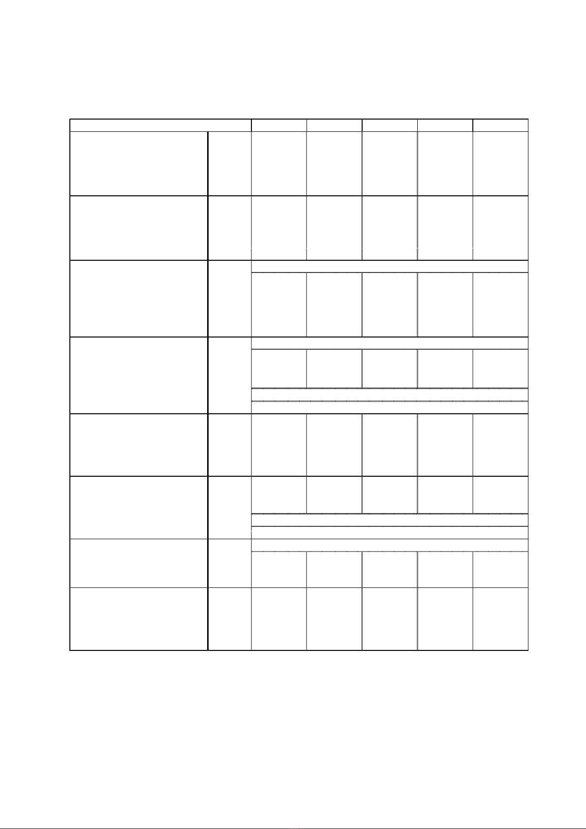
MODEL KAPPA V 2001 16.1 18.1 23.1 27.1 32.2
Cooling (*)
Nominal capacity kW 155,9 180,2 223,8 269,5 311,7
Water flow evaporator (1) l/s 7,447 8,608 10,691 12,878 14,894
l/h 26.810 30.990 38.489 46.360 53.619
Pressure drop evaporator kPa 39,6 45,2 26,7 38,7 39,6
Heating (**)
Nominal capacity kW 154,5 178,7 219,5 263,4 309,1
Water flow condenser (1) l/s 7,383 8,536 10,487 12,586 14,767
l/h 26.580 30.728 37.753 45.311 53.160
Pressure drop condenser kPa 38,9 44,5 25,7 37 38,9
Compressors tipo
Number n11112
Absorbed power cooling (*) kW 60,1 69,5 83,9 100,1 120,3
Absorbed power heating (**) kW 58,4 67,5 81,4 97,1 116,7
Capacity steps % 0-50-100 0-50-100 0-50-100 0-50-100 0-25-50-
75-100
Condenser cooling fans type
Total air flow m3/s 10,833 10,833 22,222 20,889 21,111
m3/h 39.000 39.000 80.000 75.200 76.000
Fan motor capacity n x kW 2 x 2,0 2 x 2,0 4 x 2,0 4 x 2,0 4 x 2,0
Nominal fan speed RPM
Motor power supply V/Ph/Hz
Refrigerant charge
Chiller version kg 1 x 38 1 x 39 1 x 68 1 x 82 2 x 38
Heat pump version kg 1 x 44,0 1 x 45,0 1 x 81,4 1 x 95 2 x 44,0
Oil
Oil charge kg 1 x 10 1 x 10 1 x 11 1 x 11 2 x 10
Oil brand
Oil Type
Evaporator type
Evaporator water content l 1 x 14,3 1 x 15,7 1 x 22,0 1 x 22,0 2 x 14,3
Exchanger max working pressure
waterside bar3030252530
Dimensions and weights
Length mm 2.649 2.649 2.789 2.789 2.796
Width mm 1.256 1.256 2.303 2.303 2.280
Height mm 2.385 2.385 2.385 2.385 2.385
Shipping weight kg 1.305 1.331 1.842 1.892 2.583
(1) total water flow
(*) outside air temperature 35 °C; water temperature entering/leaving evaporator 12-7 °C.
(**) outside air temperature 8 °C BS, 50% U.R. - water temperature entering/leaving condenser 40-45 °C.
DEA
SE 170
semiermetico a vite
assiali
900
400V 3 ~ 50Hz
scambiatore a piastre

b
TECHNICAL DATATECHNICAL DATA
TECHNICAL DATATECHNICAL DATA
TECHNICAL DATA
Refrigerant R407cRefrigerant R407c
Refrigerant R407cRefrigerant R407c
Refrigerant R407c
MODEL KAPPA V 2001 37.2 41.2 46.2 50.2 55.2
Cooling (*)
Nominal capacity kW 360,3 403,9 447,5 493,3 539,1
Water flow evaporator (1) l/s 17,217 19,3 21,383 23,569 25,755
l/h 61.980 69.479 76.978 84.849 92.719
Pressure drop evaporator kPa 45,2 29,9 36,7 32,4 38,7
Heating (**)
Nominal capacity kW 357,3 398,1 439 482,9 526,9
Water flow condenser (1) l/s 17,071 19,023 20,974 23,073 25,173
l/h 61.456 68.481 75.506 83.064 90.622
Pressure drop condenser kPa 44,5 29 35,3 31,1 37
Compressors tipo
Number n
Absorbed power cooling (*) kW 139,1 153,5 167,9 184 200,2
Absorbed power heating (**) kW 134,9 148,9 162,9 178,5 194,1
Capacity steps %
Condenser cooling fans type
Total air flow m3/s 21,667 31,5 31,556 42,556 41,778
m3/h 78.000 113.400 113.600 153.200 150.400
Fan motor capacity n x kW 4 x 2,0 6 x 2,0 6 x 2,0 8 x 2,0 8 x 2,0
Nominal fan speed RPM
Motor power supply V/Ph/Hz
Refrigerant charge
Chiller version kg 2 x 39 2 x 61 2 x 61 1 x 82 2 x 82
+ 1 x 68
Heat pump version kg 2 x 45,0 2 x 74 2 x 74 1 x 95 2 x 95
+ 1 x 81,4
Oil
Oil charge kg 2 x 10 1 x 11 2 x 11 2 x 11 2 x 11
+ 1 x 10
Oil brand
Oil Type
Evaporator type
Evaporator water content l 2 x 15,7 1 x 42,8 1 x 42,8 2 x 22,0 2 x 22,0
Exchanger max working pressure
waterside bar3025252525
Dimensions and weights
Length mm 2.796 3.991 3.991 5.201 5.201
Width mm 2.280 2.280 2.280 2.280 2.280
Height mm 2.385 2.385 2.385 2.385 2.385
Shipping weight kg 2.625 3.267 3.412 3.899 3.961
(1) total water flow
(*) outside air temperature 35 °C; water temperature entering/leaving evaporator 12-7 °C.
(**) outside air temperature 8 °C BS, 50% U.R. - water temperature entering/leaving condenser 40-45 °C.
scambiatore a piastre
DEA
SE 170
0-25-50-75-100
2
900
400V 3 ~ 50Hz
semiermetico a vite
assiali

c
TECHNICAL DATATECHNICAL DATA
TECHNICAL DATATECHNICAL DATA
TECHNICAL DATA Refrigerant R407cRefrigerant R407c
Refrigerant R407cRefrigerant R407c
Refrigerant R407c
CHARACTERISTICS AND ELECTRICAL DATACHARACTERISTICS AND ELECTRICAL DATA
CHARACTERISTICS AND ELECTRICAL DATACHARACTERISTICS AND ELECTRICAL DATA
CHARACTERISTICS AND ELECTRICAL DATA
(1) Electric power supply which must be available from the net
(2) Current of intervention of the internal protections of unit. It is the max absorbed current of unit. This value is
never exceeded and must be utilized to dimension the line supply and the protections (see el. diagram of unit).
The values in parenthesis are referred to /ST versions (units with storage tank) or units with pumps only
MODEL KAPPA V 2001 16.1 18.1 23.1 27.1 32.2
Max absorbed power (1) Kw 74,3 85,3 106,1 124,9 148,6
Kw (74,3) (85,3) (111,6) (134,1) (157,8)
Max starting current A 163 196 256 279 295
A (163) (196) (268) (298) (314)
Max absorbed current (2) A 132 148 184 212 264
A (132) (148) (196) (231) (283)
Nominal capacity fan motor kW
Nominal current fan motor kW
Nominal capacity pump motor kW
Nominal current pump motor A
Power supply V/Ph/Hz
Control power supply V/Ph/Hz
2 x 2,0
2 x 4,0
4 x 2,0
4 x 4,0
400V 3N ~ 50Hz ±5% V
230V 1 ~ 50Hz ±5% V
---
---
(1 x 5,5)
(1 x 12,0)
MODEL KAPPA V 2001 37.2 41.2 46.2 50.2 55.2
Max absorbed power (1) Kw 170,6 191,4 208,2 231 249,8
Kw (179,8) (200,6) (217,4) (240,2) (259)
Max starting current A 344 404 432 463 491
A (363) (423) (451) (482) (510)
Max absorbed current (2) A 296 332 360 396 424
A (315) (351) (379) (415) (443)
Nominal capacity fan motor kW 4 x 2,0
Nominal current fan motor kW 4 x 4,0
Nominal capacity pump motor kW (1x55)
Nominal current pump motor A (1x12)
Power supply V/Ph/Hz
Control power supply V/Ph/Hz
6 x 2,0
6 x 4,0
8 x 2,0
8 x 4,0
400V 3N ~ 50Hz ±5% V
230/~/50
(1 x 9,2)
(1 x 19,0)

d
TECHNICAL DATATECHNICAL DATA
TECHNICAL DATATECHNICAL DATA
TECHNICAL DATA Refrigerant R407cRefrigerant R407c
Refrigerant R407cRefrigerant R407c
Refrigerant R407c
VERSION WITH STORAGE TANK - STVERSION WITH STORAGE TANK - ST
VERSION WITH STORAGE TANK - STVERSION WITH STORAGE TANK - ST
VERSION WITH STORAGE TANK - ST
MODEL KAPPA V 2001 16.1 18.1 23.1 27.1 32.2
Pumps group
Water flow evaporator l/s --- --- 10,691 12,878 14,894
l/h --- --- 38.489 46.360 53.619
Nominal pump capacity kW --- --- 5,5 5,5 5,3
Available pump head kPa --- --- 253 231 205
Storage tank capacity l --- --- 600 600 600
Dimensions and weights
Length mm --- --- 2.789 2.789 2.796
Width mm --- --- 2.303 2.303 2.280
Height mm --- --- 2.385 2.385 2.385
Shipping weight kg --- --- 2.167 2.217 2.908
MODEL KAPPA V 2001 37.2 41.2 46.2 50.2 55.2
Pumps group
Water flow evaporator l/s 17,217 19,3 21,383 23,569 25,755
l/h 61980 69479 76.978 84.849 92.719
Nominal pump capacity kW 5,5 9,2 9,2 9,2 9,2
Available pump head kPa 164 219 199 186 159
Storage tank capacity l 600 750 750 750 750
Dimensions and weights
Length mm 2796 3.991 3.991 5.201 5.201
Width mm 2280 2.280 2.280 2.280 2.280
Height mm 2385 2.385 2.385 2.385 2.385
Shipping weight kg 2950 3.905 4.050 5.637 5.697

1
KAPPA V 2001 water chillerKAPPA V 2001 water chiller
KAPPA V 2001 water chillerKAPPA V 2001 water chiller
KAPPA V 2001 water chiller
UNIT FRAMEUNIT FRAME
UNIT FRAMEUNIT FRAME
UNIT FRAME
Self-supporting frame made from galvanised steel protected with polyester powder paint enamel (stoved at 180°)
for resistance to atmospheric agents. Stainless steel screws and bolts.
COMPRESSORS
screw-type semi-hermetic compressor, direct male rotor/female rotor drive, with crankcase heater. Lubrification
ensured by delivery and intake pressure difference.
Continuous cooling capacity control available, enabling to maximise the energetic efficiency of the unit in any
working condition.
Integral electronic motor protection and temperature sensors inserted directly in windings.
Delta-star motor start-up and standard capacity step reduction.
CONDENSERSCONDENSERS
CONDENSERSCONDENSERS
CONDENSERS
Feature tube bundle coils made of copper tubes and high-efficiency aluminium fins. The use of V condensing coils
enables to reduce the unit dimensions, as well as to increase the air suction surface.
FANSFANS
FANSFANS
FANS
Axial fans featuring sickle-shaped vane and conveyer designed to reduce noise emissions, directly driven by 6-
pole three-phase electric motor with integrated klixon thermal overload protection. IP 54 motor protection grading.
Fitted with safety fan guard.
EVAPORATOREVAPORATOR
EVAPORATOREVAPORATOR
EVAPORATOR
AISI 316 stainless steel braze-welded plate type. The use of plate-type exchangers enables to:
-
reduce the amount of refrigerant fluid in the cicuit
-
reduce the weight of the unit
-
make maintenance easier
-
reach higher COP/EER ratios
Insulated with closed-cell foam material for reduced heat loss.
All evaporators are fitted with temperature probe for anti-freeze protection.
REFRIGERANT CIRCUITREFRIGERANT CIRCUIT
REFRIGERANT CIRCUITREFRIGERANT CIRCUIT
REFRIGERANT CIRCUIT
Includes: compressor delivery valves, liquid line shut-off valve, charging connection, liquid sight glass, drier filter,
thermostatic valve, high and low pressure gauges, evaporation and condensation temperature readout by control.
ELECTRICAL PANELELECTRICAL PANEL
ELECTRICAL PANELELECTRICAL PANEL
ELECTRICAL PANEL
IP 54 category includes:
-
main switch
-
power cicuit automatic circuit breakers and fuses
-
compressor contactors
-
fan contactors
-
microprocessor for control of the following functions:
- water temperature control
- anti-freeze protection
- compressor operation timing
- compressor automatic start-up sequence
- alarm signals
- alarm reset
- potential contact for remote alarm signals
- digital display of:
-
inlet and outlet water temperature
-
temperature and differential settings
-
alarm description
-
hour meters readout of operation and number of unit, compressor and pump (if present) start-ups
- high and low pressures, relative condensation and evaporation temperature controls.

2
CONTROL AND SAFETY DEVICESCONTROL AND SAFETY DEVICES
CONTROL AND SAFETY DEVICESCONTROL AND SAFETY DEVICES
CONTROL AND SAFETY DEVICES
- manual-reset high pressure switch
- manual-reset low pressure switch
- safety valve
- mechanical flow switch
- compressor overload cut-out device
TESTSTESTS
TESTSTESTS
TESTS
Units are factory tested and come with oil and refrigerant fluid charges.
OTHER VERSIONSOTHER VERSIONS
OTHER VERSIONSOTHER VERSIONS
OTHER VERSIONS
KAPPA V 2001 /HP: reversible heat pumpKAPPA V 2001 /HP: reversible heat pump
KAPPA V 2001 /HP: reversible heat pumpKAPPA V 2001 /HP: reversible heat pump
KAPPA V 2001 /HP: reversible heat pump
Besides the standard components of the KAPPA V 2001 version, the unit includes:
- Cooling circuit: 4-way diverting valve, suction line separator, liquid accumulator, second thermostatic expansion
valve.
- Electric panel: Microprocessor is configured for summer/winter changeover and automatic defrost, autonomously
controlled for each compressor (except models 41.2 and 46.2).
KAPPA V 2001 /DC: unit with heat recovery condenserKAPPA V 2001 /DC: unit with heat recovery condenser
KAPPA V 2001 /DC: unit with heat recovery condenserKAPPA V 2001 /DC: unit with heat recovery condenser
KAPPA V 2001 /DC: unit with heat recovery condenser
Besides the standard components of the KAPPA V 2001 version, for each compressor the unit includes a 100%
heat recovery condenser for hot water production. The recovery water temperature control, the condensing
pressure step control and the safety heat recovery disabling are automatically handled by the microprocessor.
KAPPA V 2001 ST:KAPPA V 2001 ST:
KAPPA V 2001 ST:KAPPA V 2001 ST:
KAPPA V 2001 ST:
unit with storage tank and water pumpsunit with storage tank and water pumps
unit with storage tank and water pumpsunit with storage tank and water pumps
unit with storage tank and water pumps (except 16.1-18.1).(except 16.1-18.1).
(except 16.1-18.1).(except 16.1-18.1).
(except 16.1-18.1).
Besides the standard components of the KAPPA V 2001 version, the unit includes:
insulated storage tank, two water pumps, one of which in stand-by, with automatic timed commutation and in
case of failure. Expansion vessel, check valves, gate valves and mechanical flow switch installed.
KAPPA V 2001 /LE: condensing unitKAPPA V 2001 /LE: condensing unit
KAPPA V 2001 /LE: condensing unitKAPPA V 2001 /LE: condensing unit
KAPPA V 2001 /LE: condensing unit
The unit is manufactured without evaporator, thermostatic expansion valve and microprocessor control. Liquid
receivers can be supplied on request. Liquid line solenoid valves are supplied as standard equipment.
KAPPA V 2001 /LN: low noise unitKAPPA V 2001 /LN: low noise unit
KAPPA V 2001 /LN: low noise unitKAPPA V 2001 /LN: low noise unit
KAPPA V 2001 /LN: low noise unit
Besides the standard components of the KAPPA V 2001 version, the unit includes:
compressors fitted in soundproofed compartment made of painted galvanized sheet with internal insulation,
sound-absorbing mat with inserted lead plate.
ACCESSORIES:ACCESSORIES:
ACCESSORIES:ACCESSORIES:
ACCESSORIES:
- no-frost electric heater on evaporator
- fan speed regulator for operation in low ambient temperatures
- desuperheaters
- external water supply side collectors (mod. 32.2 and 37.2)
- internal water supply side collectors (mod. 50.2 and 55.2)
- rubber or spring vibration dampers
- microprocessor serial interface for supervision or tele-maintenance via personal computer
- additional compressor step control
- continuous compressor step control electronic expansion valve
- tube bundle and compressor compartment protective metal filter mesh
- compressor power factor correction
- remote control terminal
- anti-corrosion treted coils for use in aggressive atmospheres
3
THE SERIESTHE SERIES
THE SERIESTHE SERIES
THE SERIES
KAPPA.V 2001 2000 chillers and heat pump series are available in various sizes with capacities ranging from
155.9 to 539.1 kW kW (capacities refer to water temperatures at inlet/outlet of 12°/7°C, ambient air tempera-
ture 35° C) in the following basic versions:
- KAPPA.V 2001 chiller only
- KAPPA.V/HP 2001 heat pump
The model can be identified by two numbers:
Kappa V 2001 37.2Kappa V 2001 37.2
Kappa V 2001 37.2Kappa V 2001 37.2
Kappa V 2001 37.2
Nominal cooling capacity * in kW x 10 number of circuits
* Capacity refers to water inlet/outlet 12°/7°C, ambient air temperature 35°C.
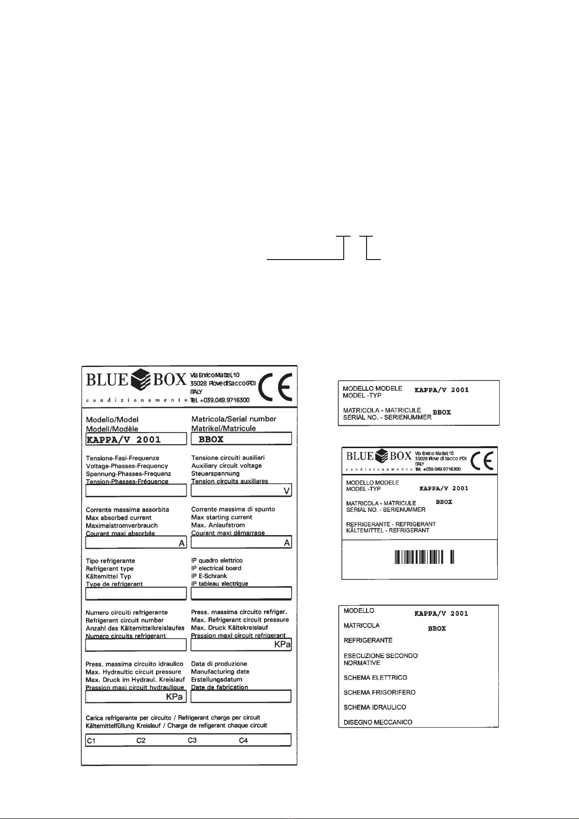
Model, factory number, technical data, electric power supply, etc. are reported on the labels of the unit.
4
Attention: Before carrying out service interventions on the unit makeAttention: Before carrying out service interventions on the unit make
Attention: Before carrying out service interventions on the unit makeAttention: Before carrying out service interventions on the unit make
Attention: Before carrying out service interventions on the unit make
sure that the power supply is disconnected.sure that the power supply is disconnected.
sure that the power supply is disconnected.sure that the power supply is disconnected.
sure that the power supply is disconnected.
All work on the unit must be carried out by qualified persons onlyAll work on the unit must be carried out by qualified persons only
All work on the unit must be carried out by qualified persons onlyAll work on the unit must be carried out by qualified persons only
All work on the unit must be carried out by qualified persons only
FIELD OF APPLICATIONFIELD OF APPLICATION
FIELD OF APPLICATIONFIELD OF APPLICATION
FIELD OF APPLICATION
These units have been designed for cooling (chiller version) or cooling/heating (heat pump version) water, generally
used in air conditioning or refrigeration applications.
Their recommended operation range is reported in paragraph 6 of this manual.
1. GENERAL1. GENERAL
1. GENERAL1. GENERAL
1. GENERAL
- When installing or servicing the unit adhere strictly to the prescriptions in this manual, conform to all specifications
and take all necessary precautions where required.
- Pressure in the refrigerant circuit and the electrical equipment present in the unit may be hazardous during
installation or servicing.
- Failure to observe the prescriptions in this manual or modification to the unit without prior and specific authorisation
will result in the immediate termination of the warranty.
2.2.
2.2.
2. INSPECTION, TRANSPORTATION AND POSITIONINGINSPECTION, TRANSPORTATION AND POSITIONING
INSPECTION, TRANSPORTATION AND POSITIONINGINSPECTION, TRANSPORTATION AND POSITIONING
INSPECTION, TRANSPORTATION AND POSITIONING
2.1 INSPECTION2.1 INSPECTION
2.1 INSPECTION2.1 INSPECTION
2.1 INSPECTION
Upon receipt of the unit, make sure that it is intact. The unit was shipped from the factory in perfect working
order and any damage must be reported to the carrier and recorded on the Delivery Note.
Blue Box or its Agent must be informed as soon as possible of the extent of any damage.
The customer should prepare a written statement and photographic evidence of any significant damage.
2.2 LIFTING AND TRANSPORTATION2.2 LIFTING AND TRANSPORTATION
2.2 LIFTING AND TRANSPORTATION2.2 LIFTING AND TRANSPORTATION
2.2 LIFTING AND TRANSPORTATION
When unloading the unit avoid any sudden movements. When moving the unit within the premises, do not apply
leverage or force to any of the appliance’s components.
The unit must be lifted using steel tubes inserted through the lifting holes marked by yellow arrows. Models 16.1
and 18.1 should be lifted using the eye-bolts located along the sides of the unit.
The unit should be lifted as per the figure below: using chords and suitably long cables and spacing bars so as not
to damage the sides and cover. If lifting platforms are used, then make sure that the width of the device is not
inferior to the width of the unit (see figure).

5
Caution Make sure that the method used for lifting does not allow theCaution Make sure that the method used for lifting does not allow the
Caution Make sure that the method used for lifting does not allow theCaution Make sure that the method used for lifting does not allow the
Caution Make sure that the method used for lifting does not allow the
unit to slip from chains and slings nor overturn or slide off lifting devices.unit to slip from chains and slings nor overturn or slide off lifting devices.
unit to slip from chains and slings nor overturn or slide off lifting devices.unit to slip from chains and slings nor overturn or slide off lifting devices.
unit to slip from chains and slings nor overturn or slide off lifting devices.
2 m min.
SPACER BARS
Min. WIDTH
2270 mm.
Min. WIDTH
2270 mm.
LIFT HERE

6
3. SAFETY REQUIREMENTS3. SAFETY REQUIREMENTS
3. SAFETY REQUIREMENTS3. SAFETY REQUIREMENTS
3. SAFETY REQUIREMENTS
3.1 DANGEROUS AREA3.1 DANGEROUS AREA
3.1 DANGEROUS AREA3.1 DANGEROUS AREA
3.1 DANGEROUS AREA
Only trained and qualified personnel should gain access to the unit.
- External dangerous area is considered an area of about 2 m around the unit. If the unit is installed in a not
protected area, it is important to install a protection to permit access only to suitably qualified person.
- The inside dangerous zone is accessible only entering inside the unit. Access inside the unit is permitted only
when the power is switched off and only to suitably qualified person.
3.2. SAFETY3.2. SAFETY
3.2. SAFETY3.2. SAFETY
3.2. SAFETY
The units are designed and built to guarantee maximum safety. In order to avoid risks to persons or objects,
adhere to the following:
- Make sure that persons using the unit have read and fully understood the manual provided before carrying out
any operations. Always keep a copy of the manual near the unit.
- Always use suitable protections (gloves, helmet, protective goggles, safety clothing etc.) before carrying out
checks or maintenance on the unit.
- Make sure to use exclusively tools and protective devices which are in good working order
- The fans are protected from external interference by persons or objects by a protective grille. Do not insert
objects or drop objects through the protective grilles.
- The heat exchanger coils have sharp edges. Avoid contact with these parts without appropriate protection.
- High temperature parts are present inside the compressor. Ensure that the correct protective measures are taken
before touching any of the unit's components when working in the vicinity.
- Do not work in the trajectory of the safety valves.
- If the units are installed in unprotected places that can be easily reached by non qualified persons, the accessory
protective grilles must be installed.

7
MECHANICAL SAFETY DATAMECHANICAL SAFETY DATA
MECHANICAL SAFETY DATAMECHANICAL SAFETY DATA
MECHANICAL SAFETY DATA
Operating Risk or danger Suggested solution
Unit operating
Maintenance
Stability.
When the unit operates do not exist any risk of
overturning. Follow carefully the instructions of this
manual.
Transport and handling Stability. To avoid overturning, the unit must be lifted using
steel tubes inserted through the lifting holes or
eyebolts located along the sides of the unit marked
by yellow arrows. Follow carefully the instructions of
this manual.
Unit operating
Maintenance
Breaking of pipes Pipes are rigidly fixed with brackets to minimize the
vibrations.
Unit operating Sharp edges. Corners and sharp edges have been reduced as
much as possible. Access to unit must be restricted
to suitably qualified persons. Should the unit be
installed in non-protected area, protection grilles
supplied as accessory have to be installed, to avoid
access inside the unit. Removal of grilles is possible
only with special tools.
Maintenance Sharp edges. Inside the unit some sharp edges could be present.
Access to the inside of unit must be restricted to
suitably qualified persons who are familiar with the
potential hazards and precautions necessary for safe
operation and with the necessary protections.
Unit operating Cut The moving parts of unit are limited to protected
zones and the fans are in a not accessible space. A
fan guards according to rule UNI EN 294 protect
fans. Removal of protections is possible only with
special tools.
Maintenance Cut The moving parts of unit are limited to protected
zones and the fans are in a not accessible space. A
fan guards according to rule UNI EN 294 protect
fans.
Unit operating Lacerations and abrasions Access to unit must be restricted to suitably qualified
persons. Should the unit be installed in non-
protected area, protection grilles supplied as
accessory must be fitted to avoid the risk of minor
abrasions and lacerations with the sharp metal edges
of condenser the finned coils.
Maintenance Lacerations and abrasions. Install adequate protections to avoid the risk of
minor abrasions and lacerations with the sharp metal
edges of the finned coils.
Unit operating Injury from rotating The moving parts of unit are limited to protected
zones and the fans are in a not accessible space. A
fan guards according to rule UNI EN 294 protect
fans. Removal of protections is possible only with
special tools.
Maintenance Injury from rotating The moving parts of unit are limited to protected
zones and the fans are in a not accessible space. A
fan guards according to rule UNI EN 294 protect
fans.
Unit operating
Maintenance
Release of high-pressure
vapour and liquid. Risk of
explosion
All units are fitted with safety valves to avoid risk of
explosion.
Discharge from safety valves has to be conveyed
outside the building through a pipe to avoid damage
due to release of high-pressure vapour and liquid.

8
THERMAL SAFETY DATATHERMAL SAFETY DATA
THERMAL SAFETY DATATHERMAL SAFETY DATA
THERMAL SAFETY DATA
NOISE SAFETY DATANOISE SAFETY DATA
NOISE SAFETY DATANOISE SAFETY DATA
NOISE SAFETY DATA
ELECTRICAL SAFETY DATAELECTRICAL SAFETY DATA
ELECTRICAL SAFETY DATAELECTRICAL SAFETY DATA
ELECTRICAL SAFETY DATA
Operating Risk or danger Suggested solution
Unit operating
Maintenance
Burns due to high
temperatures.
Insulating material protects the most part of the hot
pipes, which could produce burns. Access to unit
must be restricted to suitably qualified persons.
Should the unit be installed in non-protected area,
protection grilles supplied as accessory have to be
installed, to avoid access inside the unit. Removal of
grilles is possible only with special tools.
Maintenance
Burns due to high
temperatures
Insulating material protects the most part of the hot
pipes, which could produce burns. Protection grilles
supplied as accessory have to be installed, to avoid
access inside the unit. Removal of grilles is possible
only with special tools.
Unit operating
Maintenance
Operating difficulties –
Danger for the hearing.
The emission of noise has been reduced to a
minimum.
Direct contact with live
equipments.
Live parts in case of failure.
Not adequate insulation.
Unit operating
Maintenance
Thermal radiation due to
short-circuits or overloads.
Units built in conformity with the requirements EN
60204-1.

9
REFRIGERANT SAFETY DATA - R407CREFRIGERANT SAFETY DATA - R407C
REFRIGERANT SAFETY DATA - R407CREFRIGERANT SAFETY DATA - R407C
REFRIGERANT SAFETY DATA - R407C
Identification of the
preparation:
407C
Synonyms: HFC-32lHFC-125IHFG134a
Formula: Mixture
1. IDENTIFICATION OF
THE SUBSTANCE
1.1
EE-No: difluoromethane (HFC-32) : 200-839-4
1-1-1-2-tetrafluoroethane UHFC-134a) : 212-377-0
pentafluoroethane (HFC-125) : 206-557-8
Chemical Name CAS-No - Wt % - Symbol(s): & phrases "R"
difluoromethane 75/10/5 - 23 - F+;R12
1-2-2-2-tetrafluoroethane 811/97/2 - 52
2. COMPOSITION /
INFORMATION ON
INGREDIENTS
pentafluoroethane 354/33/ 6 - 25
3. HAZARDS
IDENTIFICATION:
3.1 Most important
hazards:
Liquefied gas: may cause frostbite. Contact with eyes may cause
irritation.
Eyes Rinse immediately with plenty of water for at least 15 minutes.
Keep eye wide open while rinsing. If symptoms persist, call a
physician.
Skin Liquefied gas may cause frostbite. Wash frostbitten areas with
plenty of water. Do not remove clothing. Wash off with warm
water. if skin irritation persists, call a physician.
Inhalation Move to fresh air in case of accidental inhalation of vapours.
Oxygen or artificial respiration if needed. Do not apply artificial
respiration if patient is breathing; Consult a physician after
significant exposure. Do not give adrenaline or similar drugs.
Ingestion Do not induce vomiting without medical advice. Call a physician
immediately. Do not give drugs from adrenaline-ephedrine
group.
4. FIRST-AID
MEASURES:
4.1
General advice Consult a physician alter significant exposure.
5.1 Suitable extinguishing
media:
The product itself does not burn. Extinguish with carbon dioxide,
dry chemical, foam or water spray. Use extinguishing measures
that are appropriate to the environment.
5.2 Extinguishing media
which must not be
used for safety reasons:
None
5.3 Specific hazards: Possibility of generating hazardous reactions during a fire due to
the presence of F and/or Cl groups. Fire or intense heat may
cause violent rupture of packages.
5.4 Special protective
equipment for fire-
fighters:
In case of fire, west a self contained breathing apparatus.
Protective suit.
5. FIRE-FIGHTING
MEASURES:
5.5 Specific methods: Standard procedure for chemical fires. In the event of fire, cool
tanks with water spray.
6.1 Personal precautions:
Use
personal protective equipment. Evacuate personnel to safe
areas. Do not breath vapours or spray mist. Ensure adequate
ventilation.
6. ACCIDENTAL
RELEASE MEASURES:
6.2 Methods for cleaning
up:
Shut off leaks it without risk. Solid evaporates. Ensure adequate
ventilation.
10
REFRIGERANT SAFETY DATA - R407CREFRIGERANT SAFETY DATA - R407C
REFRIGERANT SAFETY DATA - R407CREFRIGERANT SAFETY DATA - R407C
REFRIGERANT SAFETY DATA - R407C
7.1 Handling: Keep away from heat, sources of ignition. Do not puncture or
drop container, Provide sufficient air exchange and / or exhaust in
work rooms.
7. HANDLING AND
STORAGE:
7.2 Storage: Keep containers tightly closed in a cool, well-ventilated place.
Store in a cool and shaded area. Do not expose to temperatures
above 50 °C. Keep tightly closed.
8.1
Engineering measures
to reduce exposure:
Ensure adequate ventilation, especially in confined areas.
Personal protection
equipment:
Respiratory protection: In case of insufficient ventilation wear suitable respiratory
equipment, preferably a compressed airline breathing apparatus.
Hand protection: Impervious butyl rubber gloves.
Eye protection: Wear as appropriate: safety glasses, gaggles, Wear face-shield
and protective suit for abnormal processing problems.
8.2
Skin and body
protection:
Chemical resistant apron, long sleeved clothing, safety shoes.
8. EXPOSURE
CONTROLS /
PERSONAL
PROTECTION:
8.3
Exposure limit(s): 1-1-1-2-tetrafluoroethane 1000 ppm (TWA);
difluoromethane: 1000 ppm (TWA);
pentafluoroethane: 1000 ppm (TWA)(AIHA);
9.1 Stability: Stable at normal conditions. No decomposition if stored and
applied as directed. Decomposition starting from 250°C.
9.2 Conditions to avoid: Do not expose to temperatures above 50 °C. Fire or Intense heat
may cause violent rupture of packages.
9.3 Materials to avoid: alkaline metals (Na, K), alkaline earth metals (Ca, Mg), finely
divided aluminium, zinc.
9. STABILITY AND
REACTIVITY:
9.4
Hazardous
decomposition
products:
halogenated compounds, hydrogen halides (HF, HCI), carbonyl
halides (COCl2), carbon monoxide, carbon dioxide (C02).
10.1 Acute toxicity: LC50/inh./4 h/rat : > 500000 ppm
10.2 Irritation :
Skin: slightly irritant, may cause frostbite.
Eyes: slightly irritant.
10. TOXICOLOGICAL
INFORMATION:
10.4 Chronic toxicity: chronic inhalation, no-observed-effect level (NOEL):> 10000pprn
rat.
11.1 Waste from residues /
unused products:
Offer surplus and non-recyclable solutions to an established
disposal company. In accordance with local and national
regulations. S59 - Refer to manufacturer/supplier for information
on recovery/recycling.
11. DISPOSAL
CONSIDERATIONS:
Contaminated
packaging:
Do not reuse empty containers. Empty pressure vessels should be
returned to supplier.
No. O.N.U. 3340
12. TRANSPORT
INFORMATIQN: ADR/RID UN 3340 Refrigerant gas R407C, 2, 2° A, ADR/RID
Label: 2
11
3.3 POSITIONING3.3 POSITIONING
3.3 POSITIONING3.3 POSITIONING
3.3 POSITIONING
Consider the following when determining the most suitable site for installation:
- dimensions and location of the water piping,
- electrical power supply;
- access for servicing and maintenance or repair of the unit and/or it’s components;
- floor load capacity;
- ventilation of the air cooled condenser of the unit;
- direction and exposure to solar radiation: where possible avoid exposing the condensing coil to direct sunlight;
- wind direction: the unit should be installed where it is not exposed to wind so as to avoid recirculation;
- installation surface: do not position the unit on dark coloured surfaces (e.g. tarmac surfaces) in order to avoid
overheating during operation ;
- possible reverberation of sound emissions.
All KAPPA.V 2001 series units are designed and manufactured for external installation (gardens, terraces etc.)
make sure that the unit is not covered, even partially, by trees or canopies which could obstruct proper air
circulation.
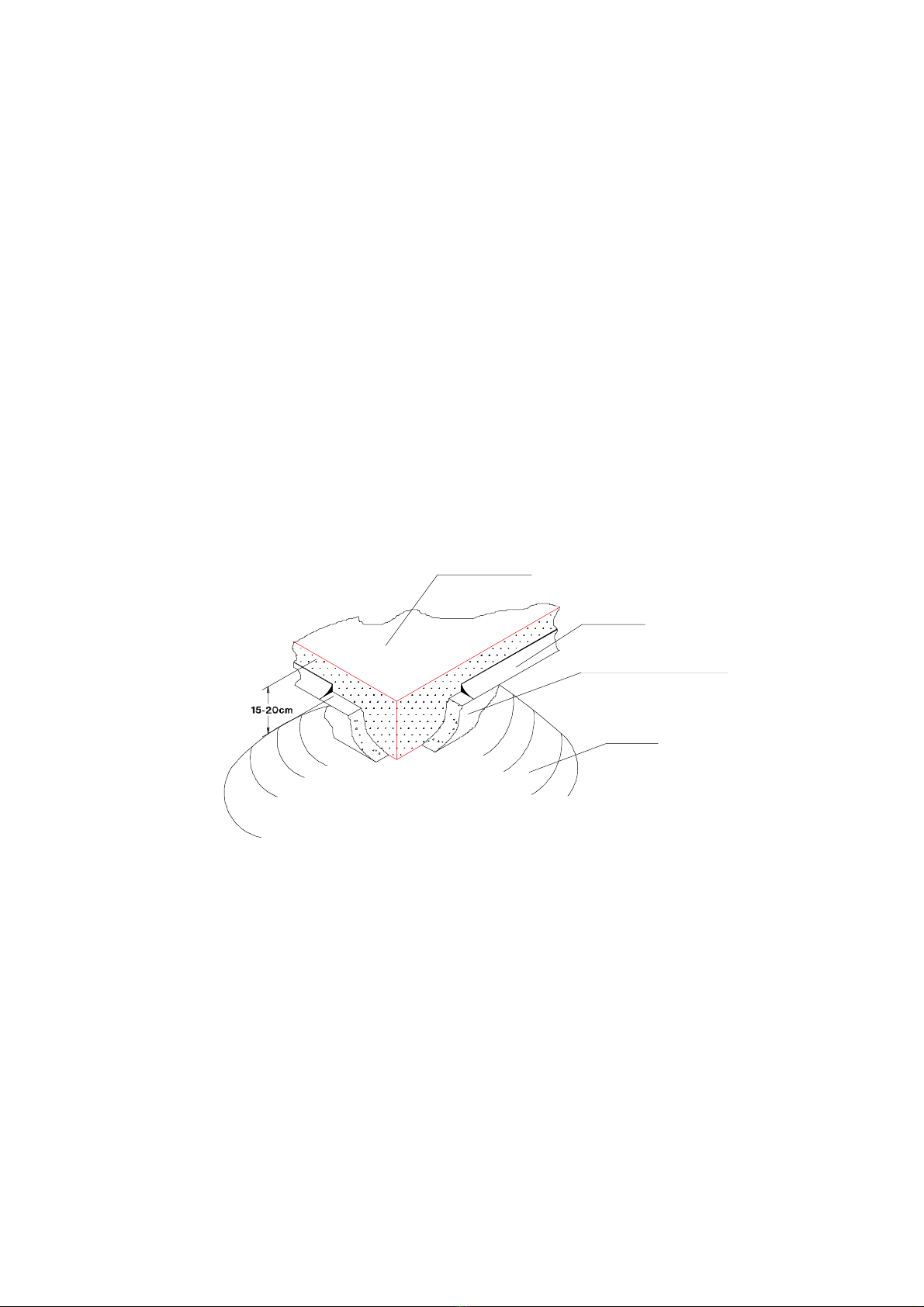
It is advisable to create a solid base support on which to position the unit. The supporting area must be completely
flat and horizontal and large enough to place the unit on. This is most important when positioning the unit directly
on the ground (gardens etc.). The following figure illustrates a typical foundation structure.
The floor slab should be:
- made with a proper foundation raised 15-20 cm above ground level,
- with a cork underlayment sealed around the perimeter,
- flat, horizontal and capable of supporting 150% of the unit’s operating weight.
- at least 30 cm longer and wider than the unit.
The units transmit low levels of vibration to the ground: it is however recommended to place hard rubber.
rubber between the subframe and the supporting surface.
Anti-vibration mounts may be required in certain situations (contact our offices).
When installing on roofs or intermediate floors, units and piping must be isolated from walls and ceilings.
Units should not be positioned near offices, bedrooms or in premises where low levels are required. It is not
recommended therefore to install the units in narrow or confined spaces in order to avoid reverberation.
FLOOR SLAB
SEALANT
CORK UNDERLAY
GROUND

12
4. INSTALLATION4. INSTALLATION
4. INSTALLATION4. INSTALLATION
4. INSTALLATION
4.1 INSTALLATION CLEARANCES4.1 INSTALLATION CLEARANCES
4.1 INSTALLATION CLEARANCES4.1 INSTALLATION CLEARANCES
4.1 INSTALLATION CLEARANCES
Absolute care must be taken to ensure adequate air volumes on the condenser coil intake and delivery sides. It
is most important to avoid recirculation between the intake and delivery: failure to observe this prescription will
result in poor performance or interruption of normal operation . It is therefore necessary to observe the following
clearances:
- around the perimeter : a minimum distance of 1.5 or 1.8 metres according to the model. (see dimension sheets).
- top: make sure air expulsion is not impeded in any way.
High walls (> 5 metres) near the machine may interfere with correct functioning. When units are side by side the
minimum distance between them should be 3 metres (see figure).
3 m
4.2 GENERAL RECOMMENDATIONS FOR WATER PIPE CONNECTION4.2 GENERAL RECOMMENDATIONS FOR WATER PIPE CONNECTION
4.2 GENERAL RECOMMENDATIONS FOR WATER PIPE CONNECTION4.2 GENERAL RECOMMENDATIONS FOR WATER PIPE CONNECTION
4.2 GENERAL RECOMMENDATIONS FOR WATER PIPE CONNECTION
Water pipelines must be installed in accordance with local and national rules and regulations (see charts enclosed
in this manual)
- Piping should be connected to the unit using flexible joints so as to avoid vibration and compensate for any
thermal expansion (adopt the same procedure for pumps)
- The following components should be installed on the pipelines:
- shut-off valves, temperature gauges and pressure gauges for regular maintenance and servicing.
- temperature probe sockets (if temperature gauges are not fitted).
- gate valves to separate the unit from the hydraulic circuit
- strainers (inlet pipes) with mesh no larger than 1 mm (obligatory in the case of plate type evaporators) to protect
heat exchangers from debris and foreign matter in pipelines.
- bleed valves installed on the upper parts of the circuit for venting of air.
- expansion tank with water filling group to maintain circuit pressure and to compensate for water thermal
expansion.
- drain cock and, where necessary, drainage tank for emptying the system during maintenance and seasonal
shutdowns.
- connection manifold between water in and out of evaporators (units with 2 independent evaporators, models:
32.2, 37.2, 50.2, 55.2), if not already ordered as option. Insert a pipe downstream the manifold to insert a
sensor to control the water leaving the chiller (option).

13
LEGEND
1 Recirculation pump
2 Expansion tank
3 Safety valve
4 Check valve
5 Ball valve
6 Tank
7 Pressure
8 Thermometer
9 Water filter
10 Bleed valve
11 Flexible coupling
12 Filling unit
13 Water cock
14 Flow switch
KAPPA V 2001 RECCOMENDED HYDRAULIC CIRCUIT
WATER TO SERVICES
WATER FROM
SERVICES
Table of contents
Other BlueBox Chiller manuals


Popular Chiller manuals by other brands


Johnson Controls
Johnson Controls York YCAL0012-0032 Start-Up Checklist

Master Bilt
Master Bilt MCR-33-101 Installation & operation instructions

Samsung
Samsung DVM installation manual

Elkay
Elkay ECP8 1H Series Installation, care & use manual

York
York YCIV0177S/P manual

SMC Networks
SMC Networks HRL100-A Operation manual

MOTIVAIR
MOTIVAIR MLC-SC-FC 0200 Installation, operation and maintenance manual

York
York YCAS0218 manual

lancer
lancer DELTA II 9100 Series Installation and service manual

York
York YK Series installation guide

Carrier
Carrier Ecologic Series 3 Controls, start-up, operation, service, and troubleshooting

Laird
Laird WL 5000 Specification and user manual