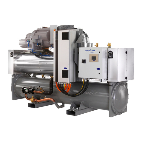
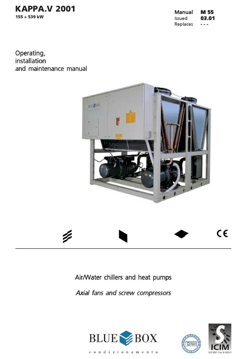
BlueBox SIGMA 2002 User manual

SIGMA 2002
42 ÷ 297 kW
00620062
00620062
0062
Water chillersWater chillers
Water chillers Water/waterWater/water
Water/waterWater/water
Water/water Scroll compressorsScroll compressors
Scroll compressorsScroll compressors
Scroll compressors
self containedself contained
self contained
Installation,Installation,
Installation,
operating,operating,
operating,
and maintenanceand maintenance
and maintenance
manualmanual
manualmanual
manual
ISO9001-Cert.n.0201
ManualManual
ManualManual
Manual 101130A02101130A02
101130A02101130A02
101130A02
Issue 12.0212.02
12.0212.02
12.02
Replaces 09.9809.98
09.9809.98
09.98


Blue Box
INDEX Page
SIGMA 2002 - water chiller 1
TECHNICAL CHARACTERISTICS 1
UNIT FRAME 1
COMPRESSORS 1
EVAPORATOR AND CONDENSER 1
REFRIGERANT CIRCUIT 1
CONTROLS AND SAFETY DEVICES 2
TESTING 2
SIGMA UNIT VERSIONS 2
SIGMA 2002/HP: reverse cycle heat pump 2
SIGMA 2002/LE: motocondensing unit 2
SIGMA2002/LE/HP:motocondensingunit 2
SIGMA 2002/LC: motoevaporating unit. 2
SIGMA 2002 / LC /HP: motoevaporating unit 2
ACCESSORY VERSIONS 2
SIGMA 2002 /DC: unit with heat recovery condenser. 2
SIGMA 2002 /DS: unit with desuperheaters 2
SIGMA LN: low noise unit 3
REFRIGERANT CIRCUIT ACCESSORIES 3
HYDRAULIC CIRCUIT ACCESSORIES 3
ELECTRICAL ACCESSORIES 3
VARIOUS ACCESSORIES 3
SERIES 4
TECHNICAL DATA Refrigerant R407C 5
ELECTRICAL CHARACTERISTICS Refrigerant R407C 9
TECHNICAL DATA Refrigerant R22 10
ELECTRICAL CHARACTERISTICS Refrigerant R22 14
SOUND POWER AND PRESSURE LEVELS 15
1. SAFETY PRECAUTIONS 16
1.1 DEFINITION OF DANGER ZONE 16
1.2 SAFETY RULES 16
MECHANICAL HAZARDS 17
THERMAL HAZARDS 18
NOISE-RELATED HAZARDS 18
ELECTRICAL HAZARDS 18
REFRIGERANT SAFETY DATA R407C 19
REFRIGERANT SAFETY DATA - R22 21
2. APPLICATION FIELD 23
2.1 GENERAL 23
3. INSPECTION, TRANSPORT, SITE HANDLING 23
3.1 INSPECTION 23
3.2 LIFTING AND SITE HANDLING 23
3.3 UNPACKING 25
3.4 LOCATION 25

Blue Box
4. INSTALLATION 26
4.1 CLEARANCES 26
4.2 ANTI-VIBRATION ISOLATORS (option) 26
4.2.1 RubberAnti-VibrationIsolators 26
4.3 WATER PIPING CONNECTIONS 27
4.4 EVAPORATOR WATER PIPE CONNECTIONS 29
4.5 CONDENSER WATER PIPE CONNECTIONS 30
4.5.1 Pressostatic valve 30
4.5.2 3 way valve 31
4.6 DESUPERHEATER HYDRAULIC CONNECTIONS (optional) 32
4.7 HEAT RECOVERY EXCHANGER HYDRAULIC CONNECTIONS (Version /DC) 32
4.8 WATER FLOW SWITCH INSTALLATION INSTRUCTIONS 34
4.9 CONNECTIONS FOR VERSION LE (MOTOCONDENSING) AND LC (MOTOEVAPORATING) 36
4.9.1 Refrigerant connections 36
4.9.2 Route of pipes and maximum distance between sections 36
4.9.3 Procedures to follow when sizing refrigerant lines 36
4.9.4 Version LE: evaporating section at lower level than condensing section: 36
4.9.5 Version LE: evaporating section positioned higher than the condensing unit section 37
TABLE 1 - EXTERNAL PIPE DIAMENTERS FOR VERSIONS LE, LE/HP 37
4.9.6 Version LC: remote condenser above the evaporating unit: 38
4.9.7 Version LC: remote air cooled condenser below the evaporating unit: 38
TABLE 2 - PIPE DIAMETER FOR VERSIONS LC 39
4.9.8 Connection of Sigma 2002 LC/HP units to a remote air cooled condenser. 39
TABLE 3 - CONNECTION PIPE EXTERNAL DIAMETERS FOR VERSIONS LC/HP 40
4.10 PRESSURE RELIEF VALVES 40
4.11 WATER QUALITY 40
4.12 LOW TEMPERATURE WATER AT CONDENSER 41
4.13 OPERATION WITH LOW TEMPERATURE CHILLED WATER AT EVAPORATOR 41
TABLE 4 - FREEZING POINT FOR WATER-ANTIFREEZE MIXTURES 41
OPERATING LIMITS 42
4.14 Water flow rate to evaporato and condenser 43
4.15 EVAPORATOR ChilleD water temperature 43
CONDENSER PRESSURE DROP 43
EVAPORATOR PRESSURE DROP 45
4.16 ELECTRICAL CONNECTIONS 46
4.16.1 General 46
4.16.2 Power supply to crankcase heaters 47
4.16.3 Potential free contacts 47
4.16.4 Flow switch electrical connections 47
4.16.5 Circulating pump electrical connections 47
4.16.6 Externalinterlock 47
4.17 MICROPROCESSOR CONTROLLERS 47
4.17.1 Microprocessor controller for /LE and HP/LE versions 48
4.17.2 RS485 serial interface (optional) 48
5. START-UP 56
5.1 PRELIMINARY CHECKS 56
6UNIT WITH mCHILLER MICROPROCESSOR (models from 3.2 to 13.2) 57
6.1.1 Display 57
6.1.2 Machinestatusinformation 57
6.1.3 Keypad 57
6.1.4 Control and display screens 58
6.1.5 Muting the BUZZER 58
6.1.6 ALARMS reset 58
6.1.7 Activation/deactivationofCOOLING operation (summermode) 59
6.1.8 Activation/deactivation of HEATING mode (winter mode) 59

Blue Box
6.1.9 Switching off the machine (stand by) 59
6.1.10 Inlet water temperature control 60
6.1.11 Defrosting (only /LC, heat pump units) 60
6.2 STARTING THE UNIT 62
6.3 STOPPING THE UNIT 62
6.3.1 Temporary stop 62
6.3.2 Seasonal stop: 63
6.4 EMERGENCY STOP 63
7. TROUBLESHOOTING 63
8UNIT WITH pCO2MICROPROCESSOR (models from 14.4 to 26.4) 71
8.1 General 71
8.1.1 Display 71
8.1.2 Keypad 71
8.2 OPERATING DESCRIPTION 73
8.2.1 Introduction 73
8.2.2 Unit in stand-by mode 73
8.2.3 Enabling the unit 73
8.2.4 Pumps management 73
8.2.5 Compressorstart-up 73
8.2.6 Chiller mode operation 73
8.2.7 Heat pump mode operation 74
8.2.8 Evaporatorlow temperature chilled water protection 74
8.2.9 Evaporator anti-freeze protection electric heater (optional) 74
8.2.10 Compressor operation 74
8.2.11 Compressor management 75
8.2.12 High and low pressure alarms 75
8.2.13 Changeover from chiller to heat pump and vice versa 75
8.2.14 Desuperheater (Option) 75
8.2.15 Total heat recovery (only SIGMA 2002/DC) 75
8.2.16 Dual set-point (option) 76
8.2.17 Leaving water temperature control (option) 76
8.2.18 Defrost (heat pumps units /LC) 76
8.3 STARTING THE UNIT 78
8.4 STOPPING THE UNIT 78
8.4.1 Temporary stop: 78
8.4.2 Seasonal stop: 78
8.5 EMERGENCY STOP 78
9TROUBLESHOOTING 79
10 CHECKS DURING OPERATION 87
10.1 Checking the refrigerant charge 87
11. CALIBRATION OF CONTROL EQUIPMENT 88
11.1 INTRODUCTION 88
TABLE 5 - CALIBRATION OF CONTROL EQUIPMENT 88
TABLE 6 - CALIBRATION OF SAFETY DEVICES 88
12. MAINTENANCE AND PERIODIC CHECKS 89
12.1 WARNINGS 89
12.2 INTRODUCTION 89
12.3 REPAIRING THE REFRIGERANT CIRCUIT 90
12.3.1 Leak test 90
12.3.2 High vacuum and dehydration of the refrigerant circuit 90
12.3.3 Refrigerantcharge 91

Blue Box
12.4 ENVIRONMENTAL CONSIDERATIONS 91
13. DECOMMISSIONING THE UNIT 92
REFRIGERANT CIRCUIT DIAGRAM 93
DIMENSIONS, WEIGHTS AND HYDRAULIC CONNECTIONS 105

Blue Box - 1
SIGMA 2002 - water chiller
Water-cooled liquid chillers with hermetic scroll compressorsand plate type evaporator, suitable for inside
installations.
TECHNICAL CHARACTERISTICS
UNIT FRAME
Self supporting frame, constructed in galvanized sheet steel with RAL 7032 powder paint baked at 180°C to
provide a durable weatherproof finish.
Models 3.2 to 7.2 and model 14.4 are completely enclosed by painted steel panels fully lined with a sound
absorbing material.
On models 8.2 to 13.2 onlytheupper compartment, which contains the compressors, is fully enclosed on all sides
by painted steel panels fully lined with a sound absorbing material.
Onmodels8.2to13.2 only the upper compartment,whichcontains the compressors, and the separatorbetween
this compartment and the lower part of the unit are enclosed by painted steel panels fully lined with a sound
absorbing material.
Models 16.4 to 26.4 do not have panels.
COMPRESSORS
Hermetic scroll type with orbital motion, connected in tandem and equipped with oil level sight glass, Klixon
internal thermal protection and oil equalisation line.
EVAPORATOR AND CONDENSER
Brazed plate type in 316 AISI stainless steel. Thermal insulation of evaporator is provided by closed cell expanded
material. Each evaporator is equipped with a low water temperature probe forfreeze protection and each unit is
equipped as standard with a mechanical flow switch.
REFRIGERANT CIRCUIT
Comprising: liquid valve, charge connection, liquid sight-glass, filter/dryer, thermostatic expansion valve with
external pressure equalisation, high and low pressure switches for 2-compressor models.
For 4-compressor models high and low pressure values and relative condensation and evaporation temperatures
are measured by pressure transducers that relay the signals to the controller so that they can be read directly on
the display. The high pressure side of the circuit is equipped with high pressure switches and relief valves.
ELECTRICAL PANEL
The electrical panel includes:
- main switch
- fuses for the auxiliary and power circuit
-compressorcontactors
- microprocessormCHILLER for 2 compressor units and PCO2 for4compressorsunits, controlling thefollowing
functions:
- water temperature regulation
-freezeprotection
-compressor time intervals
- compressor start sequence and automatic lead/lag selection
- alarm reset
- common alarm contact for remote signalling
- operating and alarm indicator LEDs
- LCD display of the following information:
- water inlet and outlet temperature
-programmed temperature set-point and differential
- alarms description
-compressor hoursrun meter for units with PCO2 control
- number of starts of the unit and the compressors
- high and low pressure values and relative condensation and evaporation temperature values.
Electrical power supply [V/f/Hz]: 400/3~/50 ±5%

Blue Box - 2
SIGMA UNIT VERSIONS
SIGMA 2002/HP: reverse cycle heat pump
The heat pump version operates as a water cooled chiller in summer and a water to water heat pump in winter
by reversing the refrigerant flow to suit the required operating mode.
In addition to the components of version SIGMA 2002, the heat pump version includes:
REFRIGERANT CIRCUIT: 4-way reversing valve and a second thermostatic expansion valve.
ELECTRICALPANEL:Microprocessor programmed for summer/winter changeover(the Macroplusmicroprocessor
is used on 4 compressor HP units).
SIGMA 2002/LE: motocondensing unit
The unit is designed to operate with a remotely located refrigerant to air evaporator. It is supplied without a
refrigerant to water evaporator and thermostatic expansion valve. The solenoid valve on the liquid line issupplied
asstandard. Models 3.2 to13.2 have mchiller controland theremainderofthe rangeis supplied withoutcontrol.
The standard supply is ON/OFF for each compressor from a digital entry.
SIGMA 2002/LE/HP: motocondensing unit
The unit is designed to operate with a remotely located refrigerant to air evaporator. It is supplied without a
refrigerant to water evaporator and thermostatic expansion valve.
The solenoid valve on the liquid line and liquid receivers are supplied as standard. Models 3.2 to 13.2 have
mCHILLER control and the remainder of the rangeissuppliedwithoutcontrol. The standard supply is ON/OFF for
each compressor from a digital entry.
SIGMA 2002/LC: motoevaporating unit.
The unit is supplied without a water cooled condenser and is designed to be connected to a remotely located air
cooled condenser.
SIGMA 2002 / LC /HP: motoevaporating unit
The unit is supplied without a water cooled condenser and is designed to be connected to a remotely located air
cooled condenser.
The solenoid valve on the liquid line and the liquid receivers are supplied as standard.
ACCESSORY VERSIONS
SIGMA 2002 /DC: unit with heat recovery condenser.
Not available for HP versions.
Inaddition to thecomponents of version SIGMA 2002 this unit includesa 100% heatrecovery condenser, for the
production of hot water, and a liquid receiver on each refrigerant circuit.
SIGMA 2002 /DS: unit with desuperheaters
Available for all models. Abrazed plate type heat recovery exchanger (desuperheater) is arranged in series with
the condenser. Also available on all HP models. In this case an isolating valve must be fitted on the water
recovery circuit and be closed during heat pump mode operation as described in the manual.
CONTROLS AND SAFETY DEVICES
- High pressure switch with manual reset.
- High pressure safety, with manual reset, controlled by the unit controller on four compressors models.
-Low pressure safety switch, with manual reset, controlled by the unitcontroller for four compressor models, low
pressure switch, with manual reset, controlled by the unit microprocessor for the two compressors models.
- High pressure relief valve
- Chilled water temperature sensor (at the evaporator inlet); on four compressors model it is installed on one
evaporator only.
- Freeze protection sensor at the outlet of each evaporator.
- Mechanical flow switch supplied as standard as kit with the unit.
-Compressorover-temperatureprotection
TESTING
The units are subjected to a dry run in the factory and supplied complete with oil and refrigerant.

Blue Box - 3
VARIOUS ACCESSORIES
-Rubberantivibrationmountings.
- Timber crate packing
- Pallet/skid for shipment in a container
- Non-standard RAL paint colours
- Unit completely pre-assembled, the unit will be supplied without refrigerant charge, test and PED certificate.
- Modular pre-asembled unit, only 4 compressors models, with the exception of model 14.4.
REFRIGERANT CIRCUIT ACCESSORIES:
- Compressor suction and discharge valves
Ball valve fitted in the equalisation line
- Pressostatic valve (with solenoid valve on heat pump)
- Liquid line solenoid valve
- Pressure gauges.
On all units with a PCO2controller the suction and discharge pressures are displayed on the controller. Gauges
on standard units are located inside the compressor compartment.
- Liquid receivers (standard on versions /LE/HP e LC/HP LC/DC e DC)
- Dual set-point.
With double thermostatic expansion valves and solenoid valves, the evaporator of “double set point units” is
sized on the basis of high temperature operation.
On units with mCHILLER control, the set must be manually modified on the microprocessor control panel.
On units with pCO2control the two values can be set from the keypad or via a digital input. In all cases the
commutation between the two thermostatic expansionvalves is automatic on the basis of the water tempera-
ture. Thermostatic expansion valve selection is made according to the temperature values specified at the time
of order. The operating limits remain unchanged and are as per the catalogue. If glycol is used, in a sufficient
percentage to avoid freezing, the lower limit of the leaving water is extended to a minimum of -5 °C.
- Condenser for well water (only standard version and LE).
HYDRAULIC CIRCUIT ACCESSORIES
- Leaving water temperature control.
Available only on units with control pCO2(not HP versions).
- Water manifold
(only 4 compressors models). Available for condensers, evaporators and heat recovery.
ELECTRICAL ACCESSORIES
- Power factor correction cos ffg0.9 at nominal operating conditions
- Single voltage-free contacts for machine status signals
- Serial interface.In unitswith amCHILLER controller(3.2-13.2) theserialinterface is the RS485type with aCarel
protocol. In units with a PC02control (from 14.4-26.4 excluding HP versions) the serial interface is the RS485
type witha Modbusprotocol.Special protocolscanbe ordered:Carel; Echelon in RS485 or FTT10 versions. HP
units can be supplied with a Macroplus microprocessor controller with aRS422typeserialinterface; refertothe
manual enclosed with the unit.
- Remote user terminal panel (in addition to the standard terminal)
Not available on HP units (with a Macroplus controller)
- Set point variable with remote signal (0-1V, 0-10V, 0-4mA, 0-20mA) available only on units with a PC02
controller, only in cooling mode. At the time of order. The set point values must be specified at the time of
order.
SIGMA LN: low noise unit
Low noise units units are completely enclosed with painted steel panels lined with sound absorption material
having an intermediate layer of high acoustic impedance material.

Blue Box - 4
SERIES
The SIGMA 2002 series of water cooled chillers, for installation inside the building, are available in various sizes
with capacities from 42 to 297 kW.
Model designations consistof two numbers:
SIGMA 2002 16.4
Shows the model number of compressors
The model, serial number, characteristics, power supply, etc. are shown by means of decals on the unit.
SERIAL NO. - SERIENUMMER
MATRICOLA - MATRICULE
Corrente massima di spunto
Max starting current
Max. Anlaufstrom
Courant maxi démarrage
Tipo refrigerante
Refrigerant type
Kältemittel Typ
Type de refrigerant
Numero circuiti refrigerante
Refrigerant circuit number
Anzahl des Kältemittelkreislaufes
Numero circuits refrigerant
Press. massima circuito idraulico
Max. Hydraultic circuit pressure
Max. Druck im Hydraul. Kreislauf
Pression maxi circuit hydraulique
Data di produzione
Manufacturing date
Erstellungsdatum
Date de fabrication
Press. massima circuito refriger.
Max. Refrigerant circuit pressure
Max. Druck Kältekreislauf
Pression maxi circuit refrigerant
IP quadro elettrico
IP electrical board
IP E-Schrank
IP tableau electrique
Tensione circuiti ausiliari
Auxiliary circuit voltage
Steuerspannung
Tension circuits auxiliares
Matricola/Serial number
(BBOX) Matrikel/Matricule
Corrente massima assorbita
Max absorbed current
Maximalstromverbrauch
Courant maxi absorbée
Modello/Model
Modell/Modèle
Tensione-Fasi-Frequenza
Voltage-Phasses-Frequency
Spannung-Phasses-Frequenz
Tension-Phasses-Fréquence
Buono di Produzione
A A
kPa
MODELLO MODELE
MODEL -TYP
kPa
Carica refrigerante per circuito(kg)/Refrigerant charge per circuit
Kältemittelfüllung KreislaufCharge de refigerant chaque circuit
(kg)
/(kg)/(kg)
C2
C1
C3
C4
REFRIGERANTE - REFRIGERANT - KÄLTEMITTEL - REFRIGERANT
MATRICOLA - MATRICULE - SERIAL NO. - SERIENUMMER
MODELLO - MODELE - MODEL - TYP
REFRIGERANTE - REFRIGERANT - KÄLTEMITTEL - REFRIGERANT
MATRICOLA - MATRICULE - SERIAL NO. - SERIENUMMER
MODELLO - MODELE - MODEL - TYP
Buono di Produzione
bar
bar
0062
0062
0062
ViaEnricoMattei,20
35028 PiovediSacco(PD)
ITALY
Tel.+039.049.9716300
ViaEnricoMattei,20
35028 PiovediSacco(PD)
ITALY
Tel.+039.049.9716300
ViaEnricoMattei,20
35028 PiovediSacco(PD)
ITALY
Tel.+039.049.9716300
REFRIGERANTE
MATRICOLA
MODELLO
ESECUZIONE SECONDO
NORMATIVE
SCHEMA ELETTRICO
SCHEMA FRIGORIFERO
SCHEMA IDRAULICO
DISEGNO MECCANICO

Blue Box - 5
(*) evaporator entering/leaving temperature 12-7 °C;
condenser entering/leaving temperature 30-35 °C
(**) condenser entering/leaving temperature 40-45 °C;
evaporator entering/leaving temperature 15-10 °C.
TECHNICAL DATATECHNICAL DATA
TECHNICAL DATA Refrigerant R407CRefrigerant R407C
Refrigerant R407CRefrigerant R407C
Refrigerant R407C
MODEL SIGMA 2002 3.2 4.2 5.2 6.2
Cooling (*)
Nominal capacity kW 42,4 51,2 59,8 68,9
Evaporator water flow l/s 2,025 2,445 2,857 3,292
(l/h) 7.290 8.800 10.285 11.851
Evaporator pressure drop kPa 49,9 45,5 39,6 36,2
Condenser water flow l/s 2,497 3,006 3,503 4,045
(l/h) 8.988 10.822 12.612 14.563
Condenser pressure drop kPa 37,9 37,9 39,4 27,1
Heating (**)
Nominal capacity kW 51,2 61,7 71,9 83
Condenser water flow l/s 2,447 2,949 3,435 3,967
(l/h) 8.809 10.616 12.367 14.280
Condenser pressure drop kPa 72,5 65,9 57 51,5
Evaporator water flow l/s 1,843 2,216 2,59 2,997
(l/h) 6.636 7.979 9.324 10.788
Evaporator pressure drop kPa 21,2 20,9 22 15,3
Compressors type
Quantity n
Refrigerant circuits n
Absorbed power cooling (*) kW 9,9 11,8 13,5 15,8
Absorbed power heating (**) kW 12,6 15,3 17,7 20,3
Capacity steps % 0-50-100 0-50-100 0-50-100 0-50-100
Refrigerant charge
Chiller version kg 1 x 3,8 1 x 4,8 1 x 5,9 1 x 8,5
Heat pump version kg 1 x 4,3 1 x 5,1 1 x 6,1 1 x 6,6
Oil
Oil charge l 2 x 3,3 2 x 3,25 2 x 3,8 1 x 4 + 1 x 3,8
Oil producer
Oil type
Evaporator type
Heat exchanger water volume l 1 x 2,9 1 x 3,8 1 x 4,9 1 x 5,5
Max operating pressure water side bar 30 30 30 30
Condenser type
Condenser water volume l 1 x 3,1 1 x 3,9 1 x 4,7 1 x 7,5
Max operating pressure water side bar 30 30 30 30
Dimension and weight
Length mm 1.334 1.334 1.334 1.334
Width mm 797 797 797 797
Heigth mm 962 962 962 962
Shipping weight kg 379 403 414 447
scroll
2
Maneurop
160 SZ
plate heat exchanger
1

Blue Box - 6
TECHNICAL DATATECHNICAL DATA
TECHNICAL DATA Refrigerant R407CRefrigerant R407C
Refrigerant R407CRefrigerant R407C
Refrigerant R407C
(*) evaporator entering/leaving temperature 12-7 °C;
condenser entering/leaving temperature 30-35 °C
(**) condenser entering/leaving temperature 40-45 °C;
evaporator entering/leaving temperature 15-10 °C.
MODEL SIGMA 2002 7.2 8.2 9.2 10.2
Cooling (*)
Nominal capacity kW 78 89,9 105,9 121,8
Evaporator water flow l/s 3,727 4,296 5,058 5,82
(l/h) 13.418 15.467 18.210 20.953
Evaporator pressure drop kPa 35,4 35 41,4 37
Condenser water flow l/s 4,587 5,291 6,236 7,18
(l/h) 16.513 19.048 22.449 25.849
Condenser pressure drop kPa 26,3 27,5 27,7 30
Heating (**)
Nominal capacity kW 94,1 108,7 128,3 147,8
Condenser water flow l/s 4,498 5,193 6,128 7,064
(l/h) 16.193 18.695 22.062 25.429
Condenser pressure drop kPa 50,5 50,2 59,3 53,4
Evaporator water flow l/s 3,404 3,91 4,615 5,32
(l/h) 12.253 14.075 16.613 19.150
Evaporator pressure drop kPa 14,8 15,4 15,6 16,8
Compressors type
Quantity n
Refrigerant circuits n
Absorbed power cooling (*) kW 18 20,8 24,6 28,5
Absorbed power heating (**) kW 22,9 26,9 31,7 36,5
Capacity steps % 0-50-100 0-50-100 0-50-100 0-50-100
Refrigerant charge
Chiller version kg 1 x 9,9 1 x 11,4 1 x 12,9 1 x 15,9
Heat pump version kg 1 x 7,7 1 x 9 1 x 10,4 1 x 13
Oil
Oil charge l 2 x 4 2 x 6,6 1 x 8 + 1 x 6,6 2 x 8
Oil producer
Oil type
Evaporator type
Heat exchanger water volume l 1 x 6,3 1 x 7,4 1 x 8,4 1 x 10,5
Max operating pressure water side bar 30 30 30 30
Condenser type
Condenser water volume l 1 x 8,75 1 x 10 1 x 11,25 1 x 13,75
Max operating pressure water side bar 30 30 30 30
Dimension and weight
Length mm 1.334 1.356 1.356 1.356
Width mm 797 768 768 768
Heigth mm 962 1.700 1.700 1.700
Shipping weight kg 470 483 560 648
scroll
2
1
plate heat exchanger
Maneurop
160 SZ
plate heat exchanger

Blue Box - 7
TECHNICAL DATATECHNICAL DATA
TECHNICAL DATA Refrigerant R407CRefrigerant R407C
Refrigerant R407CRefrigerant R407C
Refrigerant R407C
(*) evaporator entering/leaving temperature 12-7 °C;
condenser entering/leaving temperature 30-35 °C
(**) condenser entering/leaving temperature 40-45 °C;
evaporator entering/leaving temperature 15-10 °C.
MODEL SIGMA 2002 12.2 13.2 14.4 16.4
Cooling (*)
Nominal capacity kW 135,2 148,5 156 179,9
Evaporator water flow l/s 6,458 7,095 7,454 8,593
(l/h) 23.247 25.541 26.836 30.934
Evaporator pressure drop kPa 35 36,1 35,4 35
Condenser water flow l/s 7,962 8,743 9,174 10,582
(l/h) 28.663 31.477 33.026 38.096
Condenser pressure drop kPa 31,9 28,5 26,3 27,5
Heating (**)
Nominal capacity kW 164,9 182 188,3 217,4
Condenser water flow l/s 7,879 8,693 8,996 10,386
(l/h) 28.363 31.297 32.386 37.391
Condenser pressure drop kPa 51,1 53,1 50,5 50,2
Evaporator water flow l/s 5,939 6,559 6,807 7,82
(l/h) 21.382 23.613 24.506 28.150
Evaporator pressure drop kPa 18,1 16,4 14,8 15,4
Compressors type
Quantity n
Refrigerant circuits n
Absorbed power cooling (*) kW 31,5 34,5 36 41,6
Absorbed power heating (**) kW 40,6 44,7 45,8 53,7
Capacity steps % 0-50-100 0-50-100 0-25-50-75-100 0-25-50-75-100
Refrigerant charge
Chiller version kg 1 x 17,4 1x 20,7 2 x 9,9 2x 11,4
Heat pump version kg 1 x 14,4 1 x 17,8 2 x 7,7 2 x 9
Oil
Oil charge l 2 x 8 2 x 8 4 x 4 4 x 6,6
Oil producer
Oil type
Evaporator type
Heat exchanger water volume l 1 x 11,6 1 x 14,3 2 x 6,3 2 x 7,4
Max operating pressure water side bar 30 30 30 30
Condenser type
Condenser water volume l 1 x 15 1 x 17,5 2 x 8,75 2 x 10
Max operating pressure water side bar 30 30 30 30
Dimension and weight
Length mm 1.356 1.356 1.426 2.476
Width mm 768 768 801 768
Heigth mm 1.700 1.700 1.787 1.700
Shipping weight kg 688 741 810 928
24
Maneurop
160 SZ
plate heat exchanger
12
scroll

Blue Box - 8
TECHNICAL DATATECHNICAL DATA
TECHNICAL DATA Refrigerant R407CRefrigerant R407C
Refrigerant R407CRefrigerant R407C
Refrigerant R407C
(*) evaporator entering/leaving temperature 12-7 °C;
condenser entering/leaving temperature 30-35 °C
(**) condenser entering/leaving temperature 40-45 °C;
evaporator entering/leaving temperature 15-10 °C.
MODEL SIGMA 2002 18.4 20.4 24.4 26.4
Cooling (*)
Nominal capacity kW 211,7 243,6 270,3 297
Evaporator water flow l/s 10,117 11,641 12,915 14,19
(l/h) 36.420 41.906 46.494 51.083
Evaporator pressure drop kPa 41,4 37 35 36,1
Condenser water flow l/s 12,471 14,361 15,924 17,487
(l/h) 44.897 51.698 57.326 62.953
Condenser pressure drop kPa 27,7 30 31,9 28,5
Heating (**)
Nominal capacity kW 256,5 295,7 329,8 363,9
Condenser water flow l/s 12,257 14,127 15,757 17,387
(l/h) 44.124 50.858 56.726 62.593
Condenser pressure drop kPa 59,3 53,4 51,1 53,1
Evaporator water flow l/s 9,229 10,639 11,879 13,118
(l/h) 33.226 38.301 42.763 47.225
Evaporator pressure drop kPa 15,6 16,8 18,1 16,4
Compressors type
Quantity n
Refrigerant circuits n
Absorbed power cooling (*) kW 49,3 56,9 63 69
Absorbed power heating (**) kW 63,4 73 81,2 89,3
Capacity steps % 0-25-50-75-100 0-25-50-75-100 0-25-50-75-100 0-25-50-75-100
Refrigerant charge
Chiller version kg 2 x 12,9 2 x 15,9 2 x 17,4 2 x 20,7
Heat pump version kg 2 x 10,4 2 x 13 2 x 14,4 2 x 17,8
Oil
Oil charge l 2 x 8 + 1 x 6,6 4 x 8 4 x 8 4 x 8
Oil producer
Oil type
Evaporator type
Heat exchanger water volume l 2 x 8,4 2 x 10,5 2 x 11,6 2 x 14,3
Max operating pressure water side bar 30 30 30 30
Condenser type
Condenser water volume l 2 x 11,25 2 x 13,75 2 x 15 2 x 17,5
Max operating pressure water side bar 30 30 30 30
Dimension and weight
Length mm 2.476 2.476 2.476 2.476
Width mm 768 768 768 768
Heigth mm 1.700 1.700 1.700 1.700
Shipping weight kg 1.069 1.210 1.226 1.270
plate heat exchanger
Maneurop
160 SZ
scroll
2
4

Blue Box - 9
ELECTRICAL CHARACTERISTICS Refrigerant R407C
MODEL SIGMA 2002 3.2 4.2 5.2 6.2
Maximum absorbed power (1) kW 16,4 19,4 24,4 27,3
Maximum starting current A115 150 145 175
Full load current(2) A34 40 50 54
Power supply V/f/Hz
Control power supply V/f/Hz 400/3~/50
230/~/50
MODEL SIGMA 2002 7.2 8.2 9.2 10.2
Maximum absorbed power (1) kW 30,2 36,2 41,4 46,6
Maximum starting current A179 210 250 265
Full load current(2) A58 70 85 100
Power supply V/f/Hz
Control power supply V/f/Hz 400/3~/50
230/~/50
MODEL SIGMA 2002 12.2 13.2 14.4 16.4
Maximum absorbed power (1) kW 51,6 56,6 60,4 72,4
Maximum starting current A320 339 237 280
Full load current(2) A119 138 116 140
Power supply V/f/Hz
Control power supply V/f/Hz 400/3~/50
230/~/50
MODEL SIGMA 2002 18.4 20.4 24.4 26.4
Maximum absorbed power (1) kW 82,8 93,2 103,2 113,2
Maximum starting current A335 365 439 477
Full load current(2) A170 200 238 276
Power supply V/f/Hz
Control power supply V/f/Hz 400/3~/50
230/~/50
(1) mains power supply to allow unit operation.
(2) maximum current before safety cut-outs stop the unit. This value is never exceeded and must be used to size
the electrical supply cables and relevant safety devices (refer to electrical wiring diagram supplied with the
unit).

Blue Box - 10
TECHNICAL DATA Refrigerant R22
MODEL SIGMA 2002 3.2 4.2 5.2 6.2
Cooling (*)
Nominal capacity kW 42,5 51,9 59,1 68,1
Evaporator water flow l/s 2,03 2,48 2,823 3,253
(l/h) 7.309 8.928 10.162 11.710
Evaporator pressure drop kPa 48,3 45,1 37,3 34,1
Condenser water flow l/s 2,497 3,032 3,449 3,981
(l/h) 8.988 10.914 12.416 14.332
Condenser pressure drop kPa 36,5 37,2 36,9 25,3
Heating (**)
Nominal capacity kW 52,4 63,9 72,4 83,5
Condenser water flow l/s 2,505 3,051 3,458 3,989
(l/h) 9.018 10.984 12.450 14.360
Condenser pressure drop kPa 73,1 67,8 55,6 50,2
Evaporator water flow l/s 1,912 2,345 2,661 3,065
(l/h) 6.884 8.443 9.578 11.034
Evaporator pressure drop kPa 21,9 22,5 22,3 15,4
Compressors type
Quantity n
Absorbed power cooling (*) kW 9,8 11,5 13,1 15,2
Absorbed power heating (**) kW 12,4 14,8 16,7 19,3
Capacity steps %0-50-100 0-50-100 0-50-100 0-50-100
Refrigerant charge
Chiller version kg 1 x 3,8 1 x 4,8 1 x 5,9 1 x 8,5
Heat pump version kg 1 x 4,3 1 x 5,1 1 x 6,1 1 x 6,6
Oil
Oil charge l2 x 3,3 2 x 3,25 2 x 3,8 1 x 4 + 2 x 3,8
Oil producer
Oil type
Evaporator type
Heat exchanger water volume l1 x 2,9 1 x 3,8 1 x 4,9 1 x 5,5
Max operating pressure water side bar 30 30 30 30
Condenser type
Condenser water volume l1 x 1,7 1 x 2,1 1 x 2,5 1 x 1,5
Max operating pressure water side bar 30 30 30 30
Dimension and weight
Length mm 1.334 1.334 1.334 1.334
Width mm 797 797 797 797
Heigth mm 962 962 962 962
Shipping weight kg 379 403 414 447
scroll
Maneurop
160P
plate heat exchanger
2
(*) evaporator entering/leaving temperature 12-7 °C;
condenser entering/leaving temperature 30-35 °C
(**) condenser entering/leaving temperature 40-45 °C;
evaporator entering/leaving temperature 15-10 °C.

Blue Box - 11
TECHNICAL DATA Refrigerant R22
MODEL SIGMA 2002 7.2 8.2 9.2 10.2
Cooling (*)
Nominal capacity kW 77,1 88,5 104,5 120,5
Evaporator water flow l/s 3,683 4,228 4,992 5,757
(l/h) 13.257 15.220 17.972 20.725
Evaporator pressure drop kPa 33,4 32,7 39 35
Condenser water flow l/s 4,513 5,185 6,129 7,074
(l/h) 16.248 18.664 22.065 25.465
Condenser pressure drop kPa 24,5 25,5 25,8 28,1
Heating (**)
Nominal capacity kW 94,6 108,4 128,7 148,9
Condenser water flow l/s 4,519 5,18 6,148 7,116
(l/h) 16.269 18.649 22.134 25.619
Condenser pressure drop kPa 49,1 48,1 57,6 52,3
Evaporator water flow l/s 3,469 3,971 4,709 5,447
(l/h) 12.489 14.295 16.952 19.609
Evaporator pressure drop kPa 14,8 15,3 15,6 17
Compressors type
Quantity n
Absorbed power cooling (*) kW 17,4 20 23,8 27,6
Absorbed power heating (**) kW 22 25,3 30,1 34,9
Capacity steps %0-50-100 0-50-100 0-50-100 0-50-100
Refrigerant charge
Chiller version kg 1 x 9,9 1 x 11,4 1 x 12,9 1 x 15,9
Heat pump version kg 1 x 7,7 1 x 9 1 x 10,4 1 x 13
Oil
Oil charge l2 x 4 2 x 6,6 1 x 8 + 1 x 6,6 2 x 8
Oil producer
Oil type
Evaporator type
Heat exchanger water volume l1 x 6,3 1 x 7,4 1 x 8,4 1 x 10,5
Max operating pressure water side bar 30 30 30 30
Condenser type
Condenser water volume l1 x 1,8 1 x 2 1 x 2,3 1 x 2,8
Max operating pressure water side bar 30 30 30 30
Dimension and weight
Length mm 1.334 1.356 1.356 1.356
Width mm 797 768 768 768
Heigth mm 962 1.700 1.700 1.700
Shipping weight kg 470 483 560 648
scroll
2
Maneurop
160P
plate heat exchanger
(*) evaporator entering/leaving temperature 12-7 °C;
condenser entering/leaving temperature 30-35 °C
(**) condenser entering/leaving temperature 40-45 °C;
evaporator entering/leaving temperature 15-10 °C.

Blue Box - 12
TECHNICAL DATA Refrigerant R22
MODEL SIGMA 2002 12.2 13.2 14.4 16.4
Cooling (*)
Nominal capacity kW 133,7 146,9 154,2 177
Evaporator water flow l/s 6,389 7,021 7,365 8,455
(l/h) 23.000 25.275 26.514 30.440
Evaporator pressure drop kPa 33,1 34,1 33,4 32,7
Condenser water flow l/s 7,848 8,623 9,026 10,369
(l/h) 28.255 31.044 32.495 37.329
Condenser pressure drop kPa 29,9 26,7 24,5 25,5
Heating (**)
Nominal capacity kW 166,1 183,3 189,2 216,8
Condenser water flow l/s 7,937 8,758 9,038 10,36
(l/h) 28.574 31.528 32.538 37.298
Condenser pressure drop kPa 49,9 51,9 49,1 48,1
Evaporator water flow l/s 6,081 6,716 6,939 7,942
(l/h) 21.893 24.177 24.979 28.590
Evaporator pressure drop kPa 18,3 16,5 14,8 15,3
Compressors type
Quantity n
Absorbed power cooling (*) kW 30,6 33,5 34,8 40,1
Absorbed power heating (**) kW 38,8 42,7 43,9 50,6
Capacity steps %0-50-100 0-50-100 0-50-100 0-25-50-75-100
Refrigerant charge
Chiller version kg 1 x 17,4 1x 20,7 2 x 9,9 2x 11,4
Heat pump version kg 1 x 14,4 1 x 17,8 2 x 7,7 2 x 9
Oil
Oil charge l2 x 8 2 x 8 4 x 4 4 x 6,6
Oil producer
Oil type
Evaporator type
Heat exchanger water volume l1 x 11,6 1 x 14,3 2 x 6,3 2 x 7,4
Max operating pressure water side bar 30 30 30 30
Condenser type
Condenser water volume l1 x 3 1 x 3,5 2 x 1,8 2 x 2
Max operating pressure water side bar 30 30 30 30
Dimension and weight
Length mm 1.356 1.356 1.426 2.476
Width mm 768 768 801 768
Heigth mm 1.700 1.700 1.787 1.700
Shipping weight kg 688 741 810 928
2 4
scroll
Maneurop
160P
plate heat exchanger
(*) evaporator entering/leaving temperature 12-7 °C;
condenser entering/leaving temperature 30-35 °C
(**) condenser entering/leaving temperature 40-45 °C;
evaporator entering/leaving temperature 15-10 °C.

Blue Box - 13
TECHNICAL DATA Refrigerant R22
MODEL SIGMA 2002 18.4 20.4 24.4 26.4
Cooling (*)
Nominal capacity kW 209 241 267,4 293,9
Evaporator water flow l/s 9,985 11,514 12,778 14,042
(l/h) 35.944 41.449 46.000 50.550
Evaporator pressure drop kPa 39 35 33,1 34,1
Condenser water flow l/s 12,258 14,147 15,697 17,247
(l/h) 44.130 50.931 56.509 62.088
Condenser pressure drop kPa 25,8 28,1 29,9 26,7
Heating (**)
Nominal capacity kW 257,4 297,9 332,3 366,6
Condenser water flow l/s 12,297 14,233 15,874 17,516
(l/h) 44.268 51.238 57.147 63.056
Condenser pressure drop kPa 57,6 52,3 49,9 51,9
Evaporator water flow l/s 9,418 10,894 12,163 13,432
(l/h) 33.904 39.218 43.786 48.354
Evaporator pressure drop kPa 15,6 17 18,3 16,5
Compressors type
Quantity n
Absorbed power cooling (*) kW 47,6 55,1 61,1 67,1
Absorbed power heating (**) kW 60,3 69,9 77,7 85,5
Capacity steps %0-25-50-75-100 0-25-50-75-100 0-25-50-75-100 0-25-50-75-100
Refrigerant charge
Chiller version kg 2 x 12,9 2 x 15,9 2 x 17,4 2 x 20,7
Heat pump version kg 2 x 10,4 2 x 13 2 x 14,4 2 x 17,8
Oil
Oil charge l2 x 8 + 2 x 6,6 4 x 8 4 x 8 4 x 8
Oil producer
Oil type
Evaporator type
Heat exchanger water volume l2 x 8,4 2 x 10,5 2 x 11,6 2 x 14,3
Max operating pressure water side bar 30 30 30 30
Condenser type
Condenser water volume l2 x 2,3 2 x 2,8 2 x 3 2 x 3,5
Max operating pressure water side bar 30 30 30 30
Dimension and weight
Length mm 2.476 2.476 2.476 2.476
Width mm 768 768 768 768
Heigth mm 1.700 1.700 1.700 1.700
Shipping weight kg 1.069 1.210 1.226 1.270
plate heat exchanger
4
Maneurop
160P
(*) evaporator entering/leaving temperature 12-7 °C;
condenser entering/leaving temperature 30-35 °C
(**) condenser entering/leaving temperature 40-45 °C;
evaporator entering/leaving temperature 15-10 °C.

Blue Box - 14
ELECTRICAL CHARACTERISTICS Refrigerant R22
MODEL SIGMA 2002 3.2 4.2 5.2 6.2
Maximum absorbed power (1) kW 16,4 18,4 22,8 25,8
Maximum starting current A115 150 145 175
Full load current(2) A34 40 50 54
Power supply V/f/Hz
Control power supply V/f/Hz 400/3~/50
230/~/50
MODEL SIGMA 2002 7.2 8.2 9.2 10.2
Maximum absorbed power (1) kW 28,8 34 39,9 45,8
Maximum starting current A179 210 250 265
Full load current(2) A58 70 85 100
Power supply V/f/Hz
Control power supply V/f/Hz 400/3~/50
230/~/50
MODEL SIGMA 2002 12.2 13.2 14.4 16.4
Maximum absorbed power (1) kW 50,6 55,4 57,6 68
Maximum starting current A320 339 237 280
Full load current(2) A119 138 116 140
Power supply V/f/Hz
Control power supply V/f/Hz 400/3~/50
230/~/50
MODEL SIGMA 2002 18.4 20.4 24.4 26.4
Maximum absorbed power (1) kW 79,8 91,6 101,2 110,8
Maximum starting current A335 365 439 477
Full load current(2) A170 200 238 276
Power supply V/f/Hz
Control power supply V/f/Hz 400/3~/50
230/~/50
(1) mains power supply to allow unit operation.
(2) maximum current before safety cut-outs stop the unit. This value is never exceeded and must be used to size
the electrical supply cables and relevant safety devices (refer to electrical wiring diagram supplied with the
unit).
Table of contents
Other BlueBox Chiller manuals
Popular Chiller manuals by other brands
Carrier
Carrier GEMINI 09DPS018 Installation, start-up and maintenance instructions

McQuay
McQuay MAC060D4 Installation, operation & maintenance manual

Daikin
Daikin EUWA/Y5-30HB/C(Z) Service manual

Johnson Controls
Johnson Controls York YIA Series Wiring diagram

S&A
S&A CWFL-4000 user manual

York
York YCAL Series Installation operation & maintenance