BlueNova CPS 5000-King 5.2k User manual

Installation Manual
CPS 5000-King 5.2k

Table of Contents
A. INTRODUCTION
1. GENERAL INFORMATION
2. DOCUMENT SCOPE
3. TERMINOLOGY
B. SAFETY FIRST
1. GENERAL SAFETY PRECAUTIONS
2. OPERATIONAL GUIDELINES & GOOD PRACTICE
C. STRUCTURAL INFORMATION
1. LIST OF COMPONENTS
2. PRODUCT LAYOUT
D. INSTALLATION
1. PRE-INSTALLATION
1.1 Product Applications
1.2 Requirements & Limitations
1.3 Wiring Diagram
2. STANDARD INSTALLATION (UPS APPLICATION)
3. ADDING SOLAR (PV APPLICATION)
E. OPERATING INSTRUCTIONS
1. INVERTER
2. BATTERY DISPLAY PANEL
F. EMERGENCY & FIRST AID
G. SUPPORTING DOCUMENTS

A. Introduction
1. GENERAL INFORMATION
Congratulations on purchasing a high-quality BlueNova® product.
2. DOCUMENT SCOPE
This is a technical support document applicable to the following product(s):
- BlueNova® CPS 5000-King 5.2k
The information in this document includes the following
- Product Assembly & Installation Procedures
- Operating Instructions
- Maintenance & Troubleshooting Guidelines
- Emergency Procedures
3. TERMINOLOGY
The table below contains a list of industry terms used throughout this document & the
definition of each:
Term
Definition
AC
Alternating current
DC
Direct current
Product
Refers to CPS 5000-5.2k (complete) including all subcomponents.
Subcomponent
Components that the product consists of (incl. main components
such as the batteries & inverter as well as smaller components such
as switches, sockets screws & wiring)
Battery
One of either two BN52V-100-5.2k integrated batteries.
Battery Pack
Both BN52V-100-5.2k batteries, connected in serie
SoC
Battery / battery pack state of charge
DoD
Battery / battery pack depth of discharge
SoH
Battery /battery pack state of health
BMS
Battery management system
MPPT
Maximum power point tracker
UPS
Uninterruptable power supply
B. Safety First
1. GENERAL SAFETY PRECAUTIONS
Product installation should be performed by a qualified electrical technician or authorised
BlueNova® representative only, in strict accordance with the relevant instructions
contained within this document. The following precautions should be taken:

- Do not crush, burn or incinerate the product or any of its subcomponents.
- Ensure that the batteries of stored units are fully recharged at least once every 3
months in accordance with recharge procedures herein.
- Do not install the product in direct sunlight. Do not expose the product or any of its
subcomponents to temperatures exceeding 55°C.
- Avoid short-circuiting battery terminals and/or connecting batteries to other
components in reverse polarity.
- Disconnect the product from external power sources before commencing with
maintenance procedures. Some procedures might require disconnecting the battery
pack as well.
- This product has been designed for general home use. It should not be used to supply
power to life-sustaining medical appliances, automotive systems etc.
2. OPERATIONAL GUIDELINES & GOOD PRACTICE
For health & safety reasons, the following guidelines should be adhered to:
- Always wear the necessary protective gear during installation and/or maintenance.
C. Structural Information
1. LIST OF COMPONENTS
The CPS 5000-King 5.2k wall-mountable unit is shipped with the following pre-assembled
subcomponents included:
Component
Qty
Supplier
Batteries: BN52V-100-5.2k
1
BlueNova®
Inverter: Axpert King
1
Mustek
Distribution Board
1
(Miscellaneous)
Isolator Switch
1
(Miscellaneous)
Battery Display Panel
1
BlueNova®
Output Socket Sets
2
(Miscellaneous)
Nameplate
1
BlueNova®
Please also check the product packaging for the following installation components:
Component
Qty
Supplier
10mm Rawl bolt
2
(Miscellaneous)
Inverter manual
1
Mustek
Battery Display Manual
1
BlueNova®
Certificate of compliance
1
(Miscellaneous)
Apart from the above, additional supporting documentation is appended within this
document (See G. Supporting Documents). This manual as well as all other supporting
documentation is also available online at www.bluenova.co.za

2. PRODUCT LAYOUT
D. Installation
1. PRE-INSTALLATION
1.1 Product Applications
Please note that the CPS 5000-5.2k (the inverter, in particular) has been pre-configured to
be used for UPS applications. The product is therefore not “solar-ready” but can be
reconfigured for such purposes as described in D3. Adding Solar below.
1.2 Requirements & Limitations
Please refer to the data sheets & other technical documents included within this manual
to ensure that the product and/or any of its subcomponents are installed correctly.
Furthermore, in order to prolong product lifespan & ensure optimal operation the
following requirements must be met:
- The electrical input & output applied to the product should not allow for the product
or any of its subcomponents to exceed stated performance limitations.
- For non-standard applications of the product, one or more of the product’s integrated
components might have to be reconfigured to ensure compatibility with peripherals.
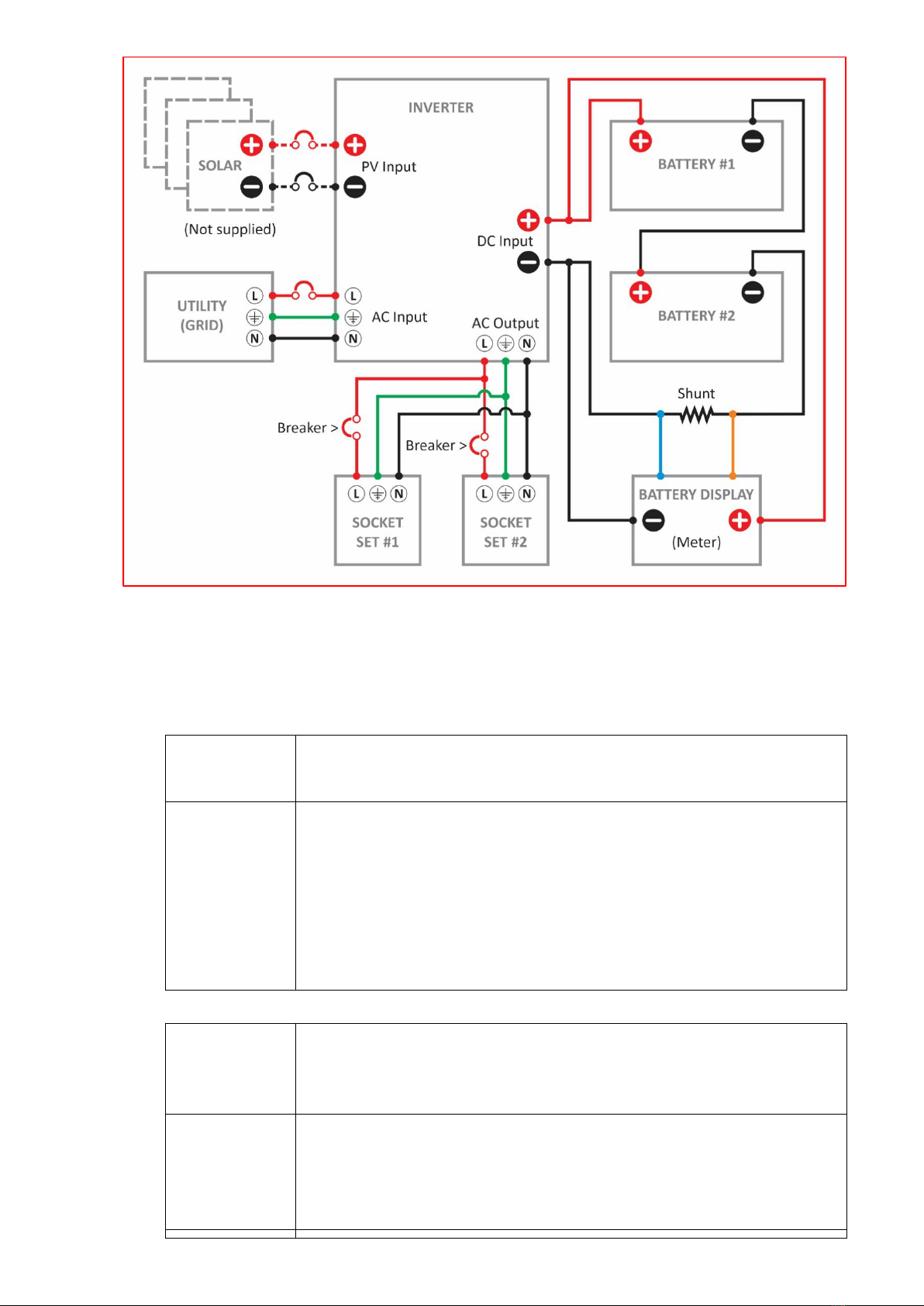
1.3 Wiring Diagram
The simplified wiring diagram below illustrates how the CPS 5000-5.2k’s components
have been connected to each other. Note that the solar panel array connection has been
illustrated even though solar panels are not supplied by BlueNova.
2. STANDARD INSTALLATION (UPS APPLICATION)
The following procedure describes how to correctly install your CPS 5000-5.2k:
STEP 1
Remove the pre-assembled main unit from the packaging. Also
remove the 2 x 10mm rawl bolts included.
STEP 2
Drill 2 x horizontally level holes spaced 68.5cm apart into a sturdy
concrete or brick wall. Use a 10mm concrete drill bit & ensure that
each hole is drilled to at least 50 mm deep.
Tip: It is recommended that the holes be drilled so that the inverter’s
display panel will end up being more or less “head height” after the
unit is installed. Refer to the product layout illustration & actual unit.
STEP 3
Unscrew the bolts from the anchor of each rawl bolt, then insert the
anchors into each of the holes. The anchors should fit snugly & flush
with the wall surface.
STEP 4
Screw each bolt back into its anchor. Ensure to leave just enough
space between the wall and lip of each bolt to allow for the pre-
assembled main unit to be hooked over the bolts when hung. A gap of
about 3mm should be sufficient.

STEP 5
Check to ensure that all subcomponents on the main unit are secure,
then tilt the whole unit upright. With one person on each side of the
unit, lift it and hook it over the installed rawl bolts in the wall.
Note: Each bolt head should fit into the respective keyhole cut-out at
the top of the unit chassis. Do not hang the unit onto the rawl bolts
from any other location(s) on the chassis other than the keyhole cut-
outs provided.
IMPORTANT: Should you install your CPS 5000-5.2k unit as a UPS application & charge it
from one of your wall sockets directly, obtaining a certificate of compliance subsequent to
installation is not necessary. Obtaining such a certificate would only be necessary if the
unit is connected to charge directly from the distribution panel on the premises.
3. ADDING SOLAR (PV APPLICATION)
A solar array can be connected to the CPS 5000-5.2k’s inverter via the integrated
distribution panel. Such installations should only be undertaken by qualified industry
personnel. Please also ensure that the solar array’s open-circuit voltage does not exceed
the maximum specified value (as per inverter data sheet appended to this document).
The suggested PV addition is 1000W with a maximum of 102V DC on the PV(solar) input
side and also a maximum charging current of 60A .(adjustable via inverter settings…)
Depending on the specific panel chosen( panel Open Circuit Voltage)2 - 3 panels might be
placed in series to achieve the necessary input voltage on the MPPT(Solar) input.
However, care should be taken regarding the maximum open circuit voltage from the
solar panel string by leaving a “buffer voltage” of + - 10V for safety purposes.
With the addition of PV onto the CPS 5000-5.2k unit, the folllowing menu items should be
adjusted :
Menu # :
01 - Output Source Priority
02 - Maximum Charging Current - utility & solar charging
11 - Maximum utility charging current
16 - Charger Source Priority
E. Operating Instructions
1. INVERTER
Please refer to the inverter manual enclosed within the product packaging.
The values with which the inverter has been preconfigured for UPS applications are listed
in this document under G. Supporting Documents

2. BATTERY DISPLAY PANEL
The integrated battery display panel displays the following variables:
3. RECOVERY FROM OVER-DISCHARGE
If the batteries are over-discharge and left uncharged for a period of time, they will enter
protection mode. To recover the batteries from this mode, follow the procedure below:
- Turn off battery circuit breaker(s) on the unit’s integrated DB.
- Turn on mains supply breaker. You have to have a working mains supply.
- Wait for 2 hours, then turn on the battery breaker(s). The inverter must start and charge the
battery with a positive current at this point. Reference the integrated battery display.
- If the batteries are not charged, repeat steps 1 to 3 above.
- Should the system not start up at this point, please contact BlueNova technical support.
F. Emergency & First Aid
1. IN CASE OF FIRE
a. Evacuate danger zone. Open ventilation in the room if possible.
b. Extinguish fire with a CO2 fire extinguisher.
c. After the fire has been extinguished, immerse any remaining smoking cells completely in
water.
Wear protective gear during this procedure.
2. SKIN CONTACT
a. Wash the affected area immediately with soap and water.
b. If irritation persists, seek medical attention.
3. EYE CONTACT
a. Rinse eyes immediately with clean water continuously for at least 15 minutes.
b. Seek medical attention immediately afterwards.
4. INGESTION
a. Refrain from taking any emetic or vomit-inducing medicine.
b. Seek medical attention immediately.
G. Supporting documents
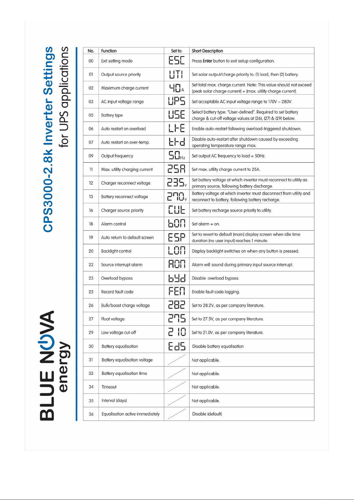
Table of contents
Popular Portable Generator manuals by other brands


Scheppach
Scheppach DGS5500 Translation of original instruction manual

King Canada
King Canada POWER FORCE KCG-10001GE instruction manual

Firman
Firman P05703 owner's manual

Hitachi
Hitachi E100 Safety instructions and instruction manual

South-Tek Systems
South-Tek Systems BREW BLAST 110CPH quick start guide

Kohler
Kohler 48RCL Operation