Blueprint Subsea seatrac X100 Series User manual

X100 Series
Acoustic Beacons
Serial Command Interface
Reference
(for firmware version 1.2)
UM-140-D00221-02


SeaTrac Serial Command Interface Reference
Page 3
Contents
1. Document Revision and Change History.......................................................................7
2. Introduction ..........................................................................................................10
2.1. Overview and Scope..........................................................................................10
2.2. Numerical Notations..........................................................................................11
2.3. Diagnostic Tools ...............................................................................................11
2.4. Technical Support............................................................................................. 11
2.5. Notices............................................................................................................ 12
3. Beacon Architecture................................................................................................13
3.1. Serial Command Processor................................................................................. 13
3.2. Settings Manager and EEPROM Memory ...............................................................13
3.3. Environmental Sensor System............................................................................14
3.4. Attitude & Heading Reference System..................................................................14
3.5. Acoustic Transceiver & Data Modem ....................................................................15
3.6. USBL Processor ................................................................................................15
3.7. Acoustic Protocol Stack...................................................................................... 16
4. Getting Started ...................................................................................................... 17
4.1. Equipment Required..........................................................................................17
4.2. Testing in air.................................................................................................... 17
4.3. Reading Beacon Information ..............................................................................18
4.4. Fetching, Updating and Storing Settings...............................................................19
4.5. Requesting Status Output .................................................................................. 20
4.6. Calibrating the AHRS.........................................................................................21
4.7. Acoustically Pinging Beacons ..............................................................................22
5. Serial Protocol........................................................................................................ 25
5.1. Serial Settings.................................................................................................. 25
5.2. Message Format ............................................................................................... 25
5.3. Synchronisation Characters................................................................................26
5.4. Data Encoding..................................................................................................26
5.5. Command ID Codes ..........................................................................................26
5.6. Checksums......................................................................................................27
6. Message Field Type and Constant Definitions.............................................................. 29
6.1. Primitive Types................................................................................................. 29
6.2. Arrays............................................................................................................. 30
6.3. Enumerations & Constants................................................................................. 30
6.3.1. AMSGTYPE_E (Acoustic Message Type) .......................................................... 31
6.3.2. APAYLOAD_E (Acoustic Payload Identifier)......................................................33
6.3.3. BAUDRATE_E (Serial Port Baud Rate) ............................................................ 34
6.3.4. BID_E (Beacon Identification Code)............................................................... 34

SeaTrac Serial Command Interface Reference
Page 4
6.3.5. CAL_ACTION_E (Calibration Actions) .............................................................35
6.3.6. CID_E (Command Identification Codes)..........................................................36
6.3.7. CST_E (Command Status Codes) ..................................................................41
6.3.8. STATUSMODE_E (Status Output Mode) ..........................................................44
6.4. Structures .......................................................................................................45
6.4.1. ACOMSG_T (Acoustic Message).....................................................................45
6.4.2. ACOFIX_T (Acoustic Position and Range Fix Summary)..................................... 46
6.4.3. AHRSCAL_T (AHRS Calibration Coefficients)....................................................50
6.4.4. FIRMWARE_T (Firmware Information)............................................................ 52
6.4.5. HARDWARE_T (Hardware Information)...........................................................53
6.4.6. IPADDR_T (IP v4 Address) ...........................................................................54
6.4.7. MACADDR_T (MAC Address).........................................................................55
6.4.8. NAV_QUERY_T (NAV Protocol Query Bit Mask) ................................................56
6.4.9. SETTINGS_T (Settings Record Structure) .......................................................57
6.4.10. STATUS_BITS_T (Status Fields Bit-Mask) ..................................................... 63
7. Beacon Management Message Definitions .................................................................. 65
7.1. System Messages .............................................................................................65
7.1.1. CID_SYS_ALIVE.......................................................................................... 65
7.1.2. CID_SYS_INFO........................................................................................... 66
7.1.3. CID_SYS_REBOOT ...................................................................................... 67
7.1.4. CID_SYS_ENGINEERING..............................................................................68
7.2. Firmware Programming Messages .......................................................................69
7.2.1. CID_PROG_INIT ......................................................................................... 70
7.2.2. CID_PROG_BLOCK...................................................................................... 72
7.2.3. CID_PROG_UPDATE .................................................................................... 74
7.3. Status Messages............................................................................................... 75
7.3.1. CID_STATUS.............................................................................................. 75
7.3.2. CID_STATUS_CFG_GET ............................................................................... 81
7.3.3. CID_STATUS_CFG_SET................................................................................82
7.4. Settings Messages ............................................................................................83
7.4.1. CID_SETTINGS_GET....................................................................................83
7.4.2. CID_SETTINGS_SET.................................................................................... 84
7.4.3. CID_SETTINGS_LOAD .................................................................................85
7.4.4. CID_SETTINGS_SAVE.................................................................................. 86
7.4.5. CID_SETTINGS_RESET ................................................................................87
7.5. Calibration Messages......................................................................................... 88
7.5.1. CID_CAL_ACTION .......................................................................................88
7.5.2. CID_AHRS_CAL_GET...................................................................................90
7.5.3. CID_AHRS_CAL_SET ...................................................................................91
7.6. Acoustic Transceiver Messages ...........................................................................92
7.6.1. CID_XCVR_ANALYSE...................................................................................92
7.6.2. CID_XCVR_TX_MSG....................................................................................94
7.6.3. CID_XCVR_RX_ERR..................................................................................... 95
7.6.4. CID_XCVR_RX_MSG.................................................................................... 97
7.6.5. CID_XCVR_RX_REQ .................................................................................... 98
7.6.6. CID_XCVR_RX_RESP................................................................................... 99

SeaTrac Serial Command Interface Reference
Page 5
7.6.7. CID_XCVR_RX_UNHANDLED....................................................................... 100
7.6.8. CID_XCVR_USBL ...................................................................................... 101
7.6.9. CID_XCVR_FIX......................................................................................... 103
7.6.10. CID_XCVR_STATUS................................................................................. 104
8. Acoustic Protocol Stack Message Definitions ............................................................. 105
8.1. PING Protocol Messages .................................................................................. 105
8.1.1. CID_PING_SEND....................................................................................... 106
8.1.2. CID_PING_REQ ........................................................................................ 108
8.1.3. CID_PING_RESP ....................................................................................... 108
8.1.4. CID_PING_ERROR..................................................................................... 109
8.2. ECHO Protocol Messages.................................................................................. 110
8.2.1. CID_ECHO_SEND...................................................................................... 110
8.2.2. CID_ECHO_REQ........................................................................................ 112
8.2.3. CID_ECHO_RESP ...................................................................................... 113
8.2.4. CID_ECHO_ERROR.................................................................................... 114
8.3. DAT Protocol Messages.................................................................................... 115
8.3.1. CID_DAT_SEND........................................................................................ 116
8.3.2. CID_DAT_RECEIVE.................................................................................... 118
8.3.3. CID_DAT_ERROR...................................................................................... 119
8.3.4. CID_DAT_QUEUE_SET............................................................................... 120
8.3.5. CID_DAT_QUEUE_CLR............................................................................... 121
8.3.6. CID_DAT_QUEUE_STATUS ......................................................................... 122
8.4. NAV Protocol Messages.................................................................................... 123
8.4.1. CID_NAV_QUERY_SEND ............................................................................ 123
8.4.2. CID_NAV_QUERY_REQ .............................................................................. 125
8.4.3. CID_NAV_QUERY_RESP............................................................................. 126
8.4.4. CID_NAV_ERROR...................................................................................... 128
8.4.5. CID_NAV_REF_POS_SEND ......................................................................... 129
8.4.6. CID_NAV_REF_POS_UPDATE...................................................................... 130
8.4.7. CID_NAV_BEACON_POS_SEND................................................................... 131
8.4.8. CID_NAV_BEACON_POS_UPDATE................................................................ 133
8.5. DEX Protocol Messages.................................................................................... 135
8.5.1. CID_DEX_CLOSE ...................................................................................... 135
8.5.2. CID_DEX_DEBUG...................................................................................... 135
8.5.3. CID_DEX_ENQUEUE .................................................................................. 135
8.5.4. CID_DEX_OPEN........................................................................................ 135
8.5.5. CID_DEX_RESET....................................................................................... 135
8.5.6. CID_DEX_SEND........................................................................................ 135
8.5.7. CID_DEX_SOCKETS .................................................................................. 135
8.5.8. CID_DEX_RECEIVE.................................................................................... 135
9. Beacon Definitions and Frames Of Reference............................................................ 136
9.1. Attitudes (Yaw, Pitch and Roll).......................................................................... 136
9.2. USBL Spherical Angles (Azimuth and Elevation) .................................................. 137
9.3. USBL Local Relative Position Coordinates ........................................................... 138
9.4. USBL World Relative Position Coordinates .......................................................... 138

SeaTrac Serial Command Interface Reference
Page 6

SeaTrac Serial Command Interface Reference
Page 7
1. Document Revision and Change History
This section details the changes that have been made to this document as a result of new
beacon firmware releases.
Developers upgrading beacon firmware should use the following summary list to check
for compatibility in command message encoding and decoding algorithms.
Revision 3 (Firmware v1.2)
Document revised for firmware release v1.2.
For standard USBL response fix calculations, ACOFIX_T structure POSITION_DEPTH
values are now given relative to the surface and not the beacon (i.e. local depth added
to USBL resolved depth)
For enhanced USBL response fix calculations, ACOFIX_T structure
POSITION_NORTHING and POSITION_EASTING values are computed based on the
remote depth, range and azimuth angle (not from standard USBL coordinates as used
previously).
SETTINGS_T structure modified to contain new Position Filter enable flag and control
fields – XCVR_POSFLT_ENABLE, XCVR_POSFLT_VEL, XCVR_POSFLT_ANG and
XCVR_POSFLT_TMO. Fields are appended on the end of the structure for backward
compatibility.
ACOFIX_T structure flags field modified to include POSITION_FLT_ERROR bit. This
indicates when the position filter (if enabled) has determine that a fix position may be
invalid based on the beacons last position, defined movement limits and time between
fixes.
Change made to the CID_NAV_BEACON_POS_UPDATE and
CID_NAV_REF_POS_UPDATE message outputs, to include an ACOFIX_T field.
Documentation now completed for the NAV protocol.
USBL detection algorithm to reduce false detects in multi-path dominant
environments.
Revision 2 (Firmware v1.1)
Document revised for firmware release v1.1.
Enumeration and structure definition changes include…
oNew ACOFIX_T structure definition added used by several commands.
oSix new CST_XCVR_STATE… codes have been added for use with the
CID_XCVR_STATUS command.
oDAT_MODE_E enumeration removed as not required.

SeaTrac Serial Command Interface Reference
Page 8
Command message changes include…
oThe 32-bit FLAGS field in the HARDWARE_T structure has been spit into two 16-
bit fields, representing system (factory set) flags, and user flags.
oCID_XCVR_RX_RESP_ERROR removed and functionality merged with
CID_XCVR_RX_ERR message.
oCID_XCVR_RX_ERR message contains the new ACOFIX_T structure describing
the received acoustic signal.
oCID_XCVR_RX_MSG, CID_XCVR_RX_REQ and CID_XCVR_RX_RESP include
ACOFIX_T structure describing the received acoustic signal.
oCID_XCVR_FIX command now uses the new ACOFIX_T structure.
oNew CID_XCVR_STATUS command added to allow the current status of the
acoustic transceiver to be queried – responses include Idle, Transmitting,
Receiving Header, Receiving Data etc.
oCID_PING_SEND command now has a MSG_TYPE field to specify how messages
are sent – either as Request Standard (MSG_REQ), Request USBL (MSG_REQU)
or Request Enhanced USBL (MSG_REQX) types. This allows finer control over
acoustic transmission types and timings.
oCID_PING_REQ and CID_PING_RESP messages now contain the new ACOFIX_T
structure – this means the XCVR_FIX_MSGS flag is no longer required to be set
in the acoustic transceiver settings.
oCID_ECHO_SEND command now has a MSG_TYPE field to specify how messages
are sent – either as Request Standard (MSG_REQ), Request USBL (MSG_REQU)
or Request Enhanced USBL (MSG_REQX) types. This allows finer control over
acoustic transmission types and timings.
oCID_ECHO_REQ and CID_ECHO_RESP messages now contain the new ACOFIX_T
structure – this means the XCVR_FIX_MSGS flag is no longer required to be set
in the acoustic transceiver settings.
oCID_DAT_SEND command now has a MSG_TYPE field (replacing FLAGS field and
obsolete DAT_MODE_E enumeration) to specify how messages are sent.
oCID_DAT_SEND command DEST_ID parameter now allows a value of
BEACON_ALL (0) to send data to all beacons. However the MSG_TYPE type must
be either MSG_OWAY or MSG_OWAYU.
oNew commands CID_DAT_QUEUE_SET, CID_DAT_QUEUE_CLR and
CID_DAT_QUEUE_STATUS added to allow data to be queued at a remote
beacon, and transmitted back in a response.
oCommand format for CID_DAT_RECEIVE updated to use the new ACOFIX_T
structure (support beacon fix information, acknowledge flag and is generated
upon receipt of an acknowledge message).
oCID_DAT_ACK message removed, as CID_DAT_RECEIVE now includes this
functionality.
Firmware bug fixed in response turnaround timing where a timing error caused a
range error of up to 1m to be reported.

SeaTrac Serial Command Interface Reference
Page 9
Transmitter waveform modified for improved performance.
Widened USBL detection window to allow greater multipath tolerance as signal is
processed by the data decoder.
Revision 1 (Firmware v1.0)
Initial documentation release for beacon firmware v1.0.

SeaTrac Serial Command Interface Reference
Page 10
2. Introduction
2.1. Overview and Scope
The SeaTrac X100 series of Micro-USBL tracking and data modems are suite of complimentary
products built around a robust broadband spread spectrum signalling scheme. These multi-
purpose acoustic transponder beacons are capable of simultaneously tracking asset positions
and undertaking bi-directional data exchange, making them ideal for use in a wide range of
applications including…
Remote monitoring and control of sensors and equipment,
Re-location and retrieval of sub-sea assets,
ROV positioning and navigation tasks,
AUV navigation, telemetry, mission adjustments and real-time position monitoring,
Diver buddy and surface-vessel/dive-bell tracking and re-location,
Remote and local depth, water temperature, attitude and heading reference (AHRS)
information.
This document is intended to provide developers with the necessary information to allow
interfacing of SeaTrac Beacons with their systems using the serial communications port
hardware and command protocol, and intended to be read in addition to the hardware and
operational notes discussed in the specific Beacon’s user manual.
The subsequent sections of this document discuss the data types, constants and structures
commonly referenced by the serial command set, along with encoding schemes and a
complete reference for the serial messages accepted and generated by the beacon.
It is assumed that the reader has a reasonable level of programming expertise and is familiar
with the basic concepts of the serial port hardware within their chosen operating system, as
well as manipulation of numerical data types and basic software design principles.
Throughout this document the following symbols are used to indicate special precautions or
procedures you should note…
WARNING!
This symbol indicates a warning you should follow of to avoid bodily injury and damage
to your equipment.
CAUTION
This symbol denotes precautions and procedures you should follow to ensure correct
operation to your equipment, and in some situations (where noted) possible damage.
NOTE
This symbol denotes special instructions or tips that should help you get the best
performance from your beacons.

SeaTrac Serial Command Interface Reference
Page 11
2.2. Numerical Notations
Throughout this document references are made to numerical values expressed in decimal,
hexadecimal or binary notation. To identify to base of numbers, the following notation is used…
Decimal Values in decimal are expressed in plain numerical digits without
any form or prefix or postfix notation.
Hexadecimal Values expressed in hexadecimal notation are always prefixed with
an “0x” notation; with uppercase characters for “A” to “F”
(although the SeaTrac Beacons serial interface will accept both
uppercase and lower case unless otherwise stated).
Binary Values expressed in a binary notation are always prefixed with an
“0b” notation, followed by a string of “1” and “0” characters.
2.3. Diagnostic Tools
To support the information and concepts presented in this document, the “SeaTrac Tools”
application has been developed for Microsoft Windows operating systems, and is shipped with
each SeaTrac Beacon system or available for download from the Technical Support web pages
(see below).
The graphical interface provides user controls and displays to send messages to and from the
beacon hardware, and the communications “Journal” function keeps track of the individual
serial commands sent and received.
Clicking on each entry in the Journal will expand the message, showing the encoding/decoding
order of each message data field and its corresponding value(s) – this information can be used
in conjunction with the message reference descriptions provided in sections 7and 8to analyse
and debug the operation of the Beacon.
2.4. Technical Support
For the latest software and firmware updates, as well as production information, manuals and
datasheets, visit www.blueprintsubsea.com/seatrac/support.php.
For further Technical Support on either software of hardware related issues please use the
contact details provided on the website above or in the Beacon’s user manual, and where
possible please have the products part number, serial number, firmware and software revision
details available.
We welcome any feedback you may have about SeaTrac products, from bug reports to ideas
for new features or hardware to support – please use the contact details on the website (or
shown below) to get in touch.

SeaTrac Serial Command Interface Reference
Page 12
2.5. Notices
Specifications and Content
The contents of this document are provided on an “as is” basis and although we try to ensure
the information presented here is correct at the time of going to press, this document may
contain some errors. Blueprint Design Engineering Ltd cannot be held responsible for any
inaccuracies or omissions. If you find an error or feel we have missed important or useful
information, please contact us. The latest version of this document is always available to
download from the website.
Specifications and information contained in this document are subject to change at any time
without notice, and does not represent a commitment on the part of Blueprint Design
Engineering Ltd.
Where possible, we will aim to re-release this document in conjunction with significant
firmware releases and updates, and will document the changes made to the documents
technical contents (commands, data structures, message formats etc) in the “Document
Revision and Change History” section (1) on page 7.
Acoustic Limitations
The operational ranges and performance that can be achieved between acoustic beacons
depends heavily on environmental factors (including water temperature, dissolved oxygen
content, marine plant life and man-made acoustic noise from passing vessels and submerged
equipment), geographical conditions (such as depth of channel, acoustic reverberation nearby
structures and obstacles that may block the acoustic transmission) and the mounting method,
orientation and position of the beacon of each operating platform.
Acoustic performance values stated in the documentation describe achievable results obtained
in favourable conditions.
Disclaimer
Neither Blueprint Design Engineering Ltd., or their affiliates shall be liable to the purchaser of
this product, or third parties, whether in tort, contract or otherwise for losses, costs, damages
or expenses incurred by the purchaser or third parties as a result of accident, misuse, abuse,
modification of this product or a failure to strictly comply with the operating and maintenance
instructions.
Trademarks
The Windows™ operating system is a trademark of the Microsoft Corporation. Other product
and brand names used within this document are for identification purposes only. Blueprint
Design Engineering Limited disclaims any and all rights in those marks.
SeaTrac Serial Command Interface Reference
Page 13
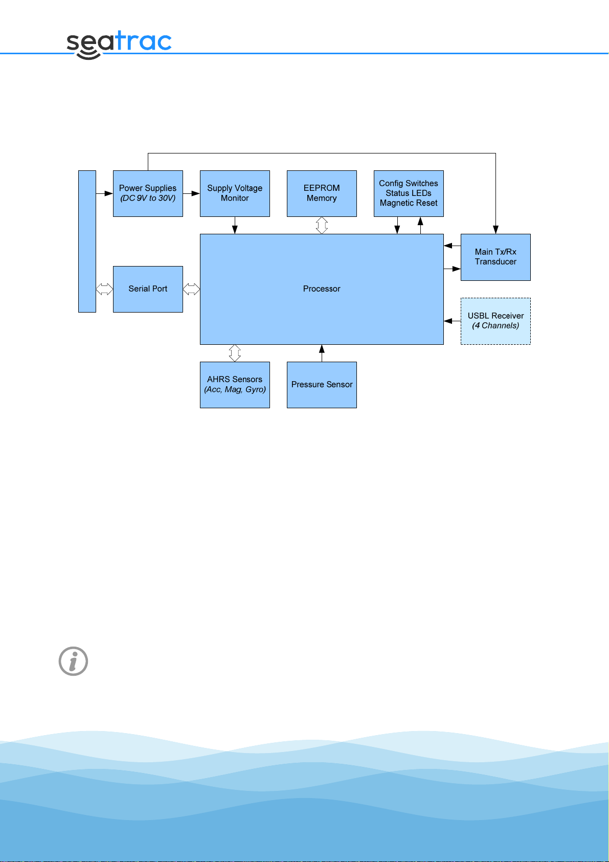
3. Beacon Architecture
The diagram below shows the hardware blocks in each beacon…
External Connector (5-way)
The X150 and X110 hardware are very similar, with the exception that X110 beacons do not
have the USBL receiver circuitry or transducers fitted.
3.1. Serial Command Processor
The serial command processor sub-system consists of a series of routines running on the
processor to decode incoming serial data into messages, ensure that correct formatting is
observed and the message content is valid by means of a checksum.
The serial UART hardware features a 64-byte hardware receive buffer, from which data is
analysed and decoded started on reception of the correct “synchronisation character”.
Decoding and buffering of the command continues until the end of the message is reached at
which time it is executed by the relevant command handler function.
Further details of the serial command protocol are discussed in section 5from page 10
onwards.
3.2. Settings Manager and EEPROM Memory
Operational settings for the Beacon are stored in permanent non-volatile EEPROM memory and
are loaded into a working RAM copy on power up.

SeaTrac Serial Command Interface Reference
Page 14
Serial commands are provided to allow the user to mage changes to the working RAM settings
or read them back, and to save of load the RAM settings back into EEPROM as required.
However, like other memories of its type, the EEPROM memory has a lifetime endurance of
between 10,000 and 50,000 cycles, after which its data retention capabilities may start to
degrade (below the guaranteed 5 year period). For this reason, it is recommended that the
settings are only saved by to EEPROM following changes by the user, but not on an automated
periodic basis.
Some settings values can be automatically computed/changed as the beacon operates, such as
pressure-sensor offsets, velocity-of-sound and magnetic calibrations. When the beacon is
powered off, these changes will be lost unless specifically committed to EEPROM with a save
command. In practice though, on dynamic platforms it is often found that storing a default
calibration for the magnetometer is sufficient for start-up accuracy and the dynamic calibration
routine will further adjust the calibration as required by the magnetic environment. Values
such as pressure offset and VOS are computed within the first couple of seconds of operation.
Some settings, such as those controlling the communication hardware, are only applied on
power-up or a software reboot command. Details of these are discussed in section 6.4.9 on
page 57.
Settings can be reset to factory values by either issuing a Reset serial command, or using the
magnetically triggered reset-to-default sequence – for further details refer to the Beacons user
manual.
3.3. Environmental Sensor System
Each beacon is fitted with an environmental pressure and temperature sensor that allow the
depth of each beacon to be calculated and monitored.
When used as part of a tracking system, the remote beacon’s depth information can be
transmitted and used as part of the position solution, improving vertical accuracy.
The pressure and temperature information can also be used to automatically update the local
velocity-of-sound value at each beacon, ensuring ranging calculations have the least possible
error.
Additionally, each beacon has a supply voltage monitoring circuit that can be used to provide
low-voltage alarms for battery powered systems. The data modem feature can be used to
optionally broadcast this information to other beacons on demand.
3.4. Attitude & Heading Reference System
Each beacon is fitted with a 9 Degrees-of-Freedom (9-DOF) Attitude and Heading Reference
System, processing data from the onboard MEMS gyroscope, accelerometer and magnetometer
to compute pitch, roll and yaw information that is made available to external applications via
the communications port.

SeaTrac Serial Command Interface Reference
Page 15
For further details on calibration procedures, refer to the Bacons user manual. Section 7.5
(from page 88) deals with calibration configuration messages.
3.5. Acoustic Transceiver & Data Modem
The Acoustic Transceiver module provides control over the beacons transmitters and receivers
allowing packets of data to be sent and received by adding and validating appropriate header
and checksum information.
Each beacon is configured by the user with a unique identification-code that allows up to 15
beacons to exchange acoustic data messages or broadcast to all other beacons in the network.
Messages are exchanged by a request/response process and when complete the sending
beacon is able to obtain timing information and a range measurement for the remotely
interrogated beacon.
When data is sent, the transceiver will use one of the message types are available…
One-Way Data is sent One-Way, and does not require a
response. (so may be broadcast to all other
beacons if required).
One-Way USBL As above, data is sent one way, but additional
USBL information is sent allowing the the receiver
X150 beacon to compute an incoming bearing,
although range cannot be provided.
Request
Request USBL
Request USBLX (Enhanced)
Data is sent from the sender to a remote beacon,
and requires that a response is returned within a
set time limit (or a timeout will occur).
From the overall trip time ranging information can
be computed, and combined with the USBL or
Enhanced information, a relative position of the
remote beacon can be computed.
Response
Response USBL
Response USBLX (Enhanced)
When a message of the above type is received,
response messages are sent back to complete the
transaction.
From this state machine in protocol handlers can
determine suitable actions to take.
3.6. USBL Processor
The X150 beacons feature an Ultra-Short Baseline (USBL) receiver array capable of calculating
the azimuth and elevation of incoming acoustic signal, and combining this information with

SeaTrac Serial Command Interface Reference
Page 16
range and the AHRS system can compute the position of the remote beacon in relative real-
world coordinates (Northing, Easting and Depth).
Tracking and navigation systems can be built using one X150 is mounted from the supervisor
vessel, with an application controlling the sequential ‘pinging’ of remote beacons. All relative
positions are computed internally and output the results via serial messages, so no additional
PC hardware is required.
In this mode up to 14 beacons may be tracked with the position of each being optionally
broadcast to others in the network, using the data modem feature.
Alternately, developers may use several X150 beacons fitted to divers or other subsea assets
and establish their own control algorithms to allow create a multiple access network where
each asset can “ping” and obtain positions for every other beacon.
3.7. Acoustic Protocol Stack
The Acoustic Protocol Stack is connected to the Acoustic Transceiver module and in a fashion
similar to the network and transportation levels of the ISO-OSI network protocol suite,
provides additional beacon functionality through the use of Acoustic Protocols.
For further details on Acoustic Protocols and their command sets, please refer to
section 8from page 105.
The supported beacon protocols are…
PING Simple Ping protocol providing the basic ability to query if a beacon is
powered-up and on its response obtain a range and position for it.
ECHO Testing and diagnostic protocol allowing packets of data to be sent to a
remove beacon and returned back to the sender.
NAV Navigation protocol, building on the ranging and positioning capabilities
of the beacon to add support for querying remote sensor information,
obtaining enhanced position fixes, and broadcasting beacons positions
to other users of the network.
DAT Datagram protocol providing commands allowing simple packets of
data to be sent to a remote beacon, and an optional acknowledgment
return made.
From this developers can implement their own data exchange
protocols.
Position and ranging information are available for each
acknowledgment received.
DEX Data Exchange protocol, building on the DAT protocol but implementing
TCP like data transfer capabilities, including sockets, port numbers,
stream buffering, transmission failure and retry facilities.

SeaTrac Serial Command Interface Reference
Page 17
4. Getting Started
When using SeaTrac Beacons for the first time, ensure that you have read the Beacon’s User
Manual first and observed all the operating requirements and precautions.
Specially, the user manual covers the connector pin-outs used for making connections to the
beacon and the requirements of the power supply.
4.1. Equipment Required
For a test and development setup it is recommended to have the following equipment…
A PC with at least one RS-232 serial port, although dual serial ports are better for
testing both ends of an acoustic link with two beacons (a variety of RS232-to-USB
serial converters have been tested at 115200 baud and proved to also work well).
If the PC has Microsoft Windows installed, having a copy of SeaTrac Tools installed is
also recommended to help validate Beacon hardware is functioning correctly and
application development progresses.
A terminal application running on the PC to validate basic operation and view output
from the beacons serial port.
For each beacon in the setup, a separate bench-top power supply capable of delivering
at least 1 amp at 12V with a smoothed DC output.
Suitable leads to connect the beacon (or beacons) to the power supplies and RS232
serial ports.
A bucket of water to place beacons while communicating acoustically (observe safe
handling procedures when using electrical items in the proximity of mains power
supplies!).
4.2. Testing in air
As mentioned above, where possible it is recommended to place beacons in a bucket of water
(or larger test tank is possible) while they are communicating acoustically.
The presence of the liquid around the transducer helps mechanically dampen it to its designed
operating levels and will reduce peak-current observed to be drawn from power supplies
during transmission.
Alternately, two separate small containers of water may be used to hold each beacon, and
operation should still be observed as the sound leaves one container, travels through air, and
enters the second.
Where possible, it is recommended to avoid prolonged operation of the beacons
acoustic transmitter out of water as the mechanical stress on the transducer element is

SeaTrac Serial Command Interface Reference
Page 18
increased (due to reduced mechanical damping).
Taking the above note into account, development and testing of the beacons in air is still
possible so long as the developer is aware of the risks.
Beacons can be placed on a bench about 30cm to 50cm apart and should communicate
acoustically with each other, although sometimes it’s more reliable to use clamp-stands to hold
them away from the surface of the desk.
Developers should also be aware that in close proximity in air, there can be electro-magnetic
cross-talk and triggering between beacons (and their cabling) rather than successful receipt of
acoustic messages.
If the velocity-of-sound value for the transmitting beacon is manually specified to be
around 340ms-1, then ranges accurate to around ±20mm should be obtained.
However, accurate and repeatable USBL positioning is not possible in air due to the
geometry of the USBL receiver array and the wavelength of sound in air.
4.3. Reading Beacon Information
For new users, it is recommended that the first activity attempted is to read and validate the
beacon information command.
First, connect a beacon to the computers serial port and run a serial terminal
application to establish a connection (several free “serial terminal” applications are
available to download from the internet).
If required set the terminal application to echo characters typed locally and append
line-feeds to carriage-return characters (so a <CR><LF> character pair is sent at the
end of messages).
When the beacon is powered up, a series of information messages should be displayed
in the terminal window along the lines of…
SEATRAC X-SERIES BEACON
Copyright (c) 2014 Blueprint Design Engineering Ltd. All rights reserved.
For further information, visit http://www.blueprintsubsea.com
Firmware Part BP00913, Version 1.0, Build 1915
Device Information...
Hardware Part Number = BP00795
Hardware Part Revision = 1
Hardware Serial Number = XXXXXX
Hardware Flags = 0x00000000
Hardware EUI48 = XX:XX:XX:XX:XX:XX
Bootloader Valid = 1
Bootloader Part Number = BP00912
Bootloader Version = v1.0.361
Bootloader Checksum = 0xBFC5FAB7
Application Valid = 1
Application Part Number = BP00913

SeaTrac Serial Command Interface Reference
Page 19
Application Version = v1.0.1915
Application Checksum = 0x4DBF60E9
Pressure Sensor Id = 20905984
Pressure Sensor Type = PA
Pressure Sensor Calibrated = 2014-03-01
Pressure Sensor Min = 0.0 bar
Pressure Sensor Max = 200.0 bar
Ready...
At this point the beacon is ready to receive serial commands. Type “#0281C1” and
press return – this will send a CID_SYS_INFO command requesting hardware and
firmware information.
Something similar to the following information string should be returned (if not a
formatting error message/code will be returned – see CST_E for appropriate return
codes)…
$0234000000011B0301690E000000000000FF900301006901B7FAC5BFFF910301007A077504
63A973BA
The fields in the above message can then be decoded using the information given in
the CID_SYS_INFO command reference section of this document. Alternately, you
could use the SeaTrac Tools application to send the above command, and use the
“Journal” to decode the information fields as…
Received Len = 41 bytes (in 83 chars)
Received Data =
"$0234000000011B0301690E000000000000FF900301006901B7FAC5BFFF910301007A07750
463A973BA"
CmdId = SYS_INFO (0x02)
Uptime = 0x00000034 (52)
Section = 0x01 (1)
HardwarePartNumber = 0x031B (795)
HardwarePartRevision = 0x01 (1)
HardwareSerialNumber = 0x00000E69 (3689)
HardwareFlags = 0x00000000 (0)
BootValid = TRUE
BootPartNumber = 0x0390 (912)
BootVersionMajor = 0x01 (1)
BootVersionMinor = 0x00 (0)
BootVersionBuild = 0x0169 (361)
BootChecksum = 0xBFC5FAB7 (3217423031)
AppValid = TRUE
AppPartNumber = 0x0391 (913)
AppVersionMajor = 0x01 (1)
AppVersionMinor = 0x00 (0)
AppVersionBuild = 0x077A (1914)
AppChecksum = 0xA9630475 (2841838709)
4.4. Fetching, Updating and Storing Settings
Using a process similar to that described in section 4.3 above, you can make you application
change the beacon settings using the following sequence of commands…

SeaTrac Serial Command Interface Reference
Page 20
First define the SETTINGS_T structure in your application – you will require this to
read settings into.
Send a CID_SETTINGS_GET command to the beacon, and parse the response into a
field of type SETTINGS_T – this will include the current sensor calibration values in
use.
Modify the settings structure as required then write values back into the Beacons RAM
using the CID_SETTINGS_SET command. Most settings will be applied immediately,
but some (such as communication settings) will only be applied following a power-up
or software reboot command.
It may be required to store these new settings back into EEPROM, in which case now
issue the CID_SETTINGS_SAVE command. Note that if automatic calculation of VOS
and pressure offset are enabled, the previously specified values will be overwritten
with the computed values.
If a reboot if required to apply communication settings, issue a CID_SYS_REBOOT
command now.
4.5. Requesting Status Output
Using a process similar to that described in section 4.3 above, you can make you application
manually request the current beacon status via a Status Output Message using the following
sequence of commands…
In the terminal application, typing “#10000DC0” will prompt for a CID_STATUS
message using the output flags configured in the settings.
Assuming the default flags of “Environment”, “AHRS” and “Magnetic Calibration” are
specified, something similar to the following message will be received…
$10078D48100000000000B930C2000800000000000000480DE3FD0DFD320303FF2B0400005E
F273
The above decodes as…
Received Len = 39 bytes (in 79 chars)
Received Data =
"$10078D48100000000000B930C2000800000000000000480DE3FD0DFD320303FF2B0400005
EF273"
CmdId = STATUS_STATE (0x10)
OutputFlags = 0x07 (7)
Timestamp = 0x000000000010488D (1067149)
EnvironmentSupply = 0x30B9 (12473)
EnvironmentTemperature = 194
EnvironmentPressure = 8
EnvironmentDepth = 0
EnvironmentVos = 0x0D48 (3400)
AttitudeYaw = -541
AttitudePitch = -755
AttitudeRoll = 818
MagCalBuf = 0x03 (3)
Table of contents


