MicroAir Avionics T2000SFL User manual
Microair Avionics Pty Ltd
Airport Drive
Bundaberg
Queensland 4670
Australia
Tel: +61 7 41 553048
Fax: +61 7 41 553049
Microair Avionics T2000SFL Transponder User Manual
T2000SFL User Manual 01R8-2 Page 2 of 28 18
th
September 2012
About This Document
Microair Avionics has developed a series of transponders for use with
OEM applications, and for commercial sale by Microair Avionics. The
manual explains the basic functions and elaborates on the more
sophisticated features, such as altitude display and alerts.
Microair reserves the right to amend this manual as required, to reflect
any enhancements or upgrades to the T2000SFL transponder series.
© Microair Avionics Pty Ltd
Statement:
The T2000SFL owner accepts all responsibility for obtaining the proper licensing before using the transponder. The
coverage you can expect from the T2000SFL is limited to “line of sight”. Low altitude or aircraft antenna shielding by the
aircraft itself may result in a reduced range. Range can be improved by climbing to a higher altitude. It may be possible to
minimize antenna shielding by locating the antenna where dead spots are only noticed during abnormal flight attitudes.
The T2000SFL should be turned off before starting or shutting down aircraft engine(s).
Mobile phones must not be turned on during the operation of the T2000SFL.
T2000SFL-01 (8)
1-6-9 software
REVISION STATUS
Revision Date Change
1.0 11/02/01 Initial Draft
2.2 11/07/01 Voltage Monitoring
2.3 22/08/01 Standby function added
2.4 05/10/01 Hi / Lo alerts added
2.5 12/10/01 Mode and Program Mode menu functions amended
2.6 07/11/01 Deleted SF references
2.7 01/06/02 Assigned Alt & Buffer Alt input amended, Name/Reg relocated to end of Program Mode
2.8 22/11/03 ID and VFR key instructions amended
2.9 08/04/05 Amended for function changes incorporated into software revision 1.6.4
01R3 11/05/06 Amended for 1.6.5 software
01R4 27/05/06 Hardware and software revision references amended Mobile phone to be turned off references
01R5 22/11/06 Display graphics updated
01R6 10/05/07 VFR and ID key descriptions amended
01R7 12/05/08 Warranty Statement Upgrade
01R7-1 19/07/08 Alarm acknowledgement added
01R7-2 25/02/09 Updated Limited Warranty Statement
01R8-0 19/08/09 T2000SFL Rev.8 introduced. Serial Alt data & VSI function added – voltage functions deleted
01R8-1 30/08/10 Firmware 1-6-9 introduced
01R8-2 18-09-12 Default setting for ENC SRC is now SERIAL

Microair Avionics T2000SFL Transponder User Manual
T2000SFL User Manual 01R8-2 Page 3 of 28 18
th
September 2012
TABLE OF CONTENTS
1.0 INTRODUCTION.............................................................................................4
1.1
T2000SFL CONTROLS ...........................................................................................................5
1.2
TURNING ON..........................................................................................................................5
1.3
TURNING OFF ........................................................................................................................5
1.4
DISPLAY LAYOUT ................................................................................................................6
1.5
SPECIAL CODES ....................................................................................................................6
2.0 DISPLAY FUNCTION.....................................................................................7
3.0 CONTROL FUNCTIONS ................................................................................8
3.1
SELECT MODE KNOB ...........................................................................................................8
3.2
CODE SELECT KNOB............................................................................................................9
3.3
ON KEY....................................................................................................................................9
3.4
MODE KEY............................................................................................................................10
3.4.1
QNH OR BARO (BAROMETRIC PRESSURE) ............................................................................................... 11
3.4.2
ASSIGNED (ALTITUDE) ................................................................................................................................. 12
3.4.3
BUFFER ALT .................................................................................................................................................... 13
3.4.4
DSP ALT ............................................................................................................................................................ 14
3.4.5
BACKLITS......................................................................................................................................................... 15
3.4.6
ALERT TONE.................................................................................................................................................... 15
3.5
ENTER KEY...........................................................................................................................16
3.6
TOGGLE KEY .......................................................................................................................16
3.7
VFR – HOT KEY ...................................................................................................................17
3.8
ID KEY ...................................................................................................................................17
4.0 INITIALISATION AND SETUP...................................................................18
4.1
PROGRAM MODE ................................................................................................................18
4.1.1
VFR CODE......................................................................................................................................................... 19
4.1.2
ENC SRCE ......................................................................................................................................................... 20
4.1.3
ALTITUDE (UNITS) ......................................................................................................................................... 21
4.1.4
BARO................................................................................................................................................................. 21
4.1.5
REM STBY ........................................................................................................................................................ 22
4.1.6
EXIT PROGRAM............................................................................................................................................... 22
5.0 FREQUENTLY ASKED QUESTIONS:.......................................................23
6.0 LIMITED WARRANTY ................................................................................27

Microair Avionics T2000SFL Transponder User Manual
T2000SFL User Manual 01R8-2 Page 4 of 28 18
th
September 2012
1.0 INTRODUCTION
The Microair T2000SFL Transponder is designed to operate in the environment of a Radar Beacon System. This
system interrogates the transponder, which in turn replies with an identity code and altitude information. The
radar system consists of a network of ground stations, which sweep the horizon like a conventional radar. When
the transponder in the aircraft detects the radar sweep (is illuminated), the transponder replies with a burst
transmission giving its identity code and altitude.
The system presents the replies from all transponders in range of the ground stations on a single display screen.
This allows ATC to easily locate, identify, and see the altitude of all traffic in their airspace.
A transponder’s reply is termed a squawk. Hence the current code being used by the transponder is termed the
squawk code. At times of high airspace activity, ATC may wish to uniquely identify an individual aircraft with a
request to squawk ident. The pilot uses the ident control on the transponder to make the transponder’s squawk on
the ATC display flash for a short period. The ident control should not be used unless ATC request it.
ATC will issue a code to an aircraft requesting entry into its controlled airspace. This code is normally unique
for each aircraft, each time that aircraft passes through the airspace. The code is 4 digits long, and each digit can
range from 0-7.
The aircraft’s transponder
receives the ground station
signal asking it to transmit. The
transponder “replies” with the
code, and if operating in mode
C, the encoder altitude.
Ground stations sweep the sky with a signal, which
asks the transponder in the aircraft to transmit its
code and altitude.

Microair Avionics T2000SFL Transponder User Manual
T2000SFL User Manual 01R8-2 Page 5 of 28 18
th
September 2012
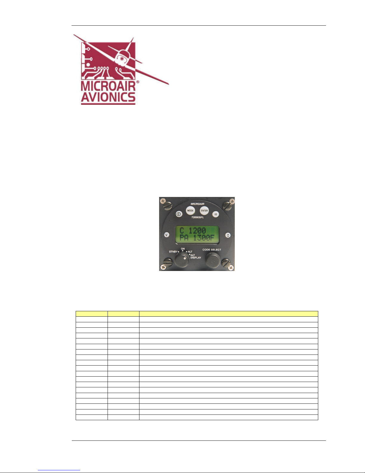
1.1 T2000SFL CONTROLS
All of the T2000SFL’s functions and features can be
accessed from the controls on the front face.
CONTROL DESCRIPTION
1 ON Key
2 MODE Key
3 ENTER Key
4 IDENT Key
5 TOGGLE Key
6 CODE SELECT Knob
7 SELECTMODE Knob
8 VFR Key
All of the keys are covered in a soft rubberized plastic, which is backlight with the display. When the key is
pressed a small click can be discerned. The selected function will operate on the release of the key.
1.2 TURNING ON
The T2000SFL is turned on by pressing the ON key. The T2000SFL
will go through a start up routine displaying self test messages,
including the display of the transponder’s serial number, a backlight
test, and ending with the operational display.
1.3 TURNING OFF
To turn off, press the ON key again, and the unit will immediately turn off.
ON KEY
Other manuals for T2000SFL
1
This manual suits for next models
3
Table of contents
Other MicroAir Avionics Marine Radio manuals


