Humminbird VHF255S-DSC User manual

VHF255S DSC MARINE RADIO
TM366-USA
25/1 Watt VHF/FM
OPERATOR WARNING
HUMMIINBIRD requires the radio operator to meet the requirements for
Radio Frequency Exposure. Unauthorized changes or modifications to
this equipment may void compliance with ***Rule.Any change or
modification must be approved in writing by HUMMIINBIRD Corp
This equipment has been tested and licensed to comply with the limits for Class
D Digital Marine Devices. These limits are designed to provide reasonable
protection against harmful interference in a residential installation. This
equipment can generate or radiate radio frequency energy and, if not installed
and used in accordance with the instructions, may cause harmful interference to
radio communications and human body. Never transmit before you make sure
the antenna is properly located.
This device is only an aid to navigation. Its performance can be affected by many
factors including equipment failure or defects, environmental condition and
improper handling or use. It is the user's responsibility to exercise common
prudence and navigational judgement, and this device should not be relied upon
as a substitute for such prudence and judgement. Your Radio Ocean VHF radio
generates and radiates radio frequency (RF) electromagnetic energy (EME). This
equipment must be installed and operated in accordance with the instructions
contained in this handbook. Failure to do so can result in personal injury and/or
product malfunction.

Page 3 Page 4
TABLE OF CONTENTS
EQUIPMETN DESCRIPTION…………………………………….……………………3
1.1 INTRODUCTION…………………………………………………………….3
2. CONTROLS AND LCD DISPLAY…………………………………………4
2.1 BASE STATION PANEL……….……………….…………………….……5
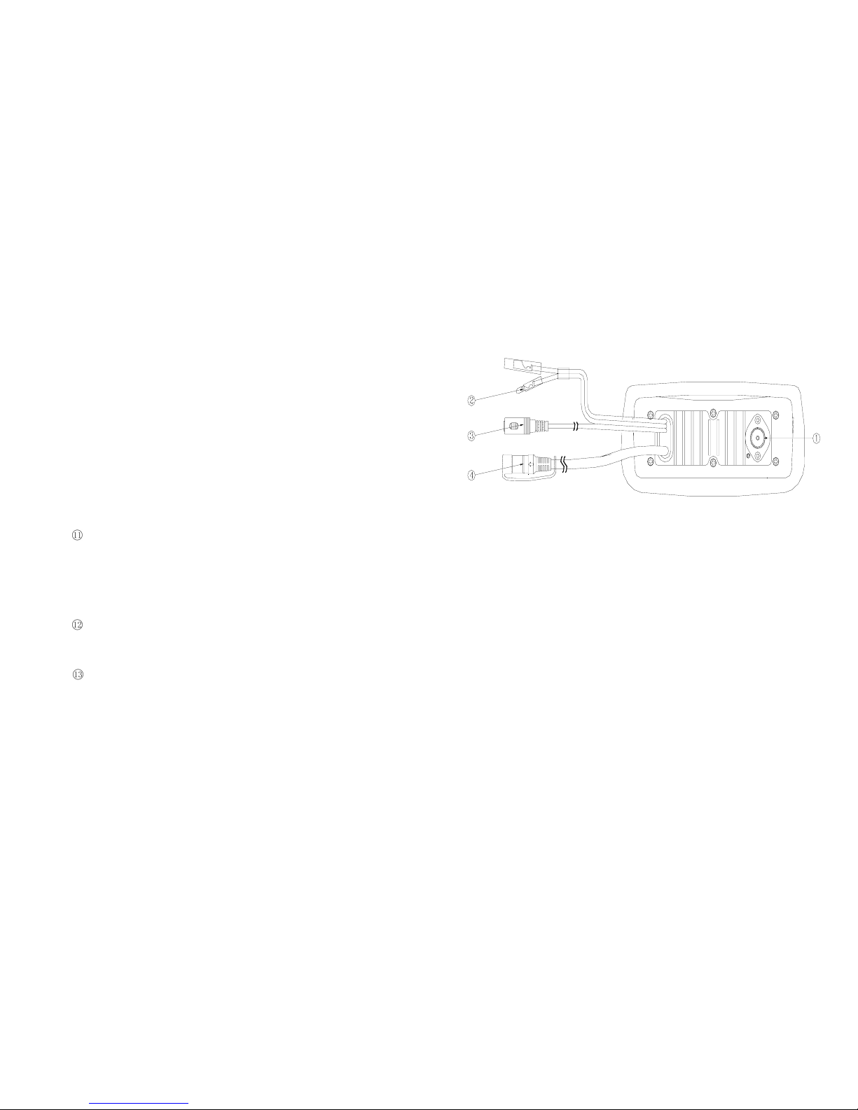
2. 2 BASE STATION PANEL (REAR)…………..……………………..………6
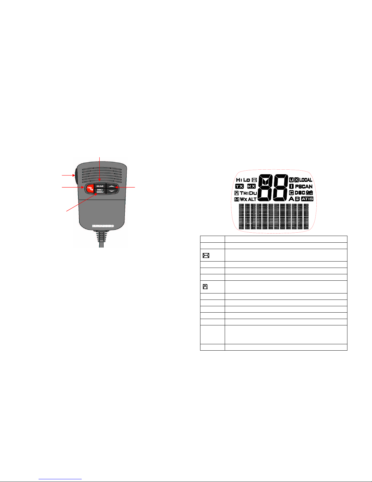
2. 3 HANDSET………………….……………………………………………...…7
2. 4 LIQUID CRYSTAL DISPLAY……..………………………………..….……8
3.I INSTALLATION…………………….……………………………….….…….8
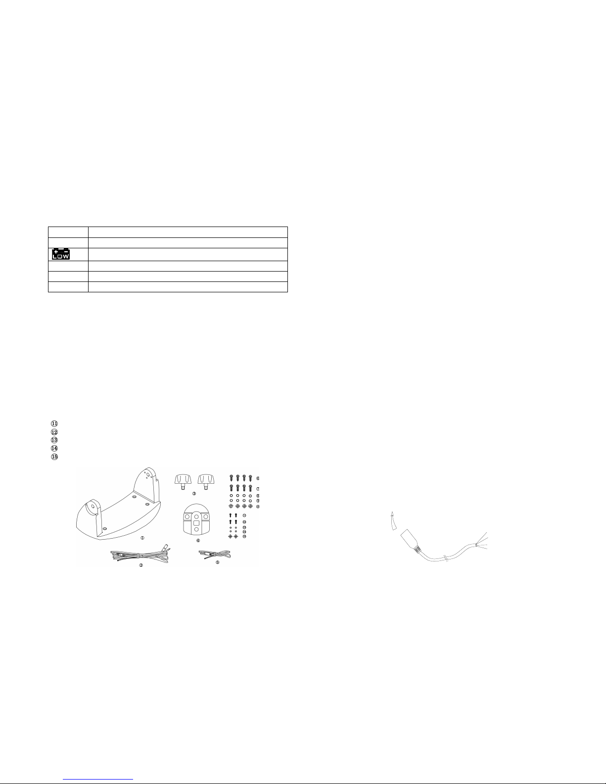
SUPPLIED ACCESSORIES………………………………………….……8
3.2 LOCATION…………………………………………………………….……8
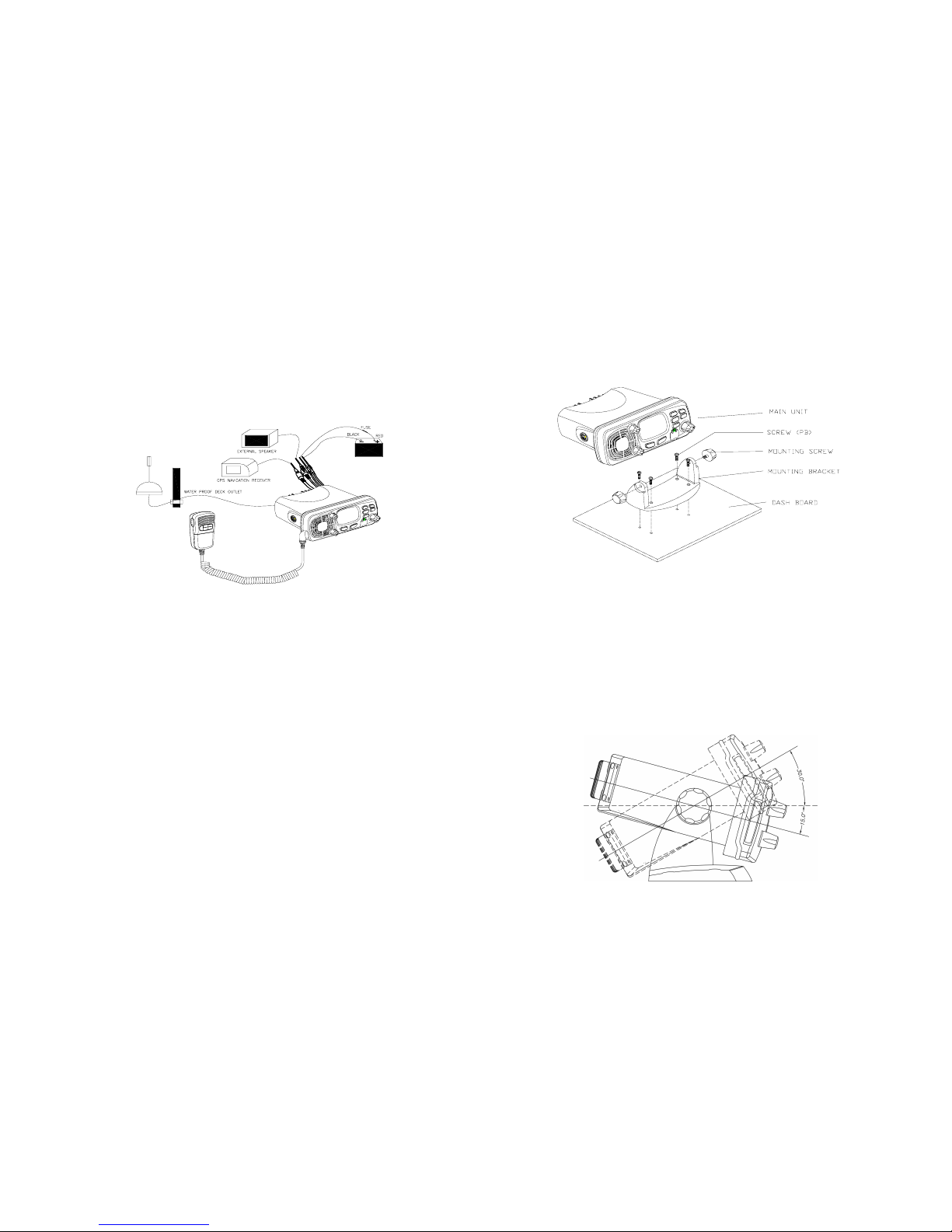
3.3 CONNECTIONS………………….………….……………………..………8
3.4 MOUNTING THE RADIO………..……..………………………………….9
3.5 ANTENNA MOUNTING/THE EMC EXPOSURE…………………..……11
3.6 MOUNTING THE HANDSET……………………………………………..12
4 BASE OPERATION………………………….………………………….…13
4.1 TRANSMISSION AND RECEPTION…….………………..…………….14
4.2 BAND SWITCH……………………….…………………………………….14
4.3 SAVE FAV CHANNELS………….………………………….………….…15
4.4 TRANSMIT TIME-OUT-TIME……………………………………………..16
4.5 SCAN………………………………………………………..………………16
4.6 WATCH ………………………………………………………..……………17
4.7.1 Dual WATCH………………………………………………….……………17
4.7.2 TRI WATCH ……………………………………………………..…………17
4.8 POSITION INDICATION……………………………..……………………17
5.0 DIGITAL SELECTIVE CALLING………………..………………….……17
5.1 GENERAL………………………………………………….….……..17
5.1.1 MARITIME MOBILE SERVICE IDENTITY(MMIS)L….…………………17
5.1.2 HOW CAN I OBTAIN MMSI ASSIGNMENT?………………………..18
5.2. DSC CALL TYPE………………………………………………………….18
5.2.1 SEND A DISTRESS CALL……………………………...……………..…19
5.2.2 SEND AN ALL SHIPS CALL…….………………………………….……20
5.2.3 SEND A GROUP CALL……………….………………………………..…21
5.2.4 MAKE A ROUTING CALL (INDIVIDUAL)………………………….…...21
5.2.4.1 MANUALLY SENDING AN INDIVIDUAL CALL……………...………..21
5.2.4.2 SENDING AN INDIVIDUAL CALL)………………………………….…..22
5.2.4.3 ACK OF AN INDIVIDUAL INCOMING………………………....……….23
5.2.5 LAST CALL………………………………………………………………...23
5.2.6 SENDING AN INDIVIDUAL CALL USING THE CALL LOG……...….23
5.2.7.1 POS REQUEST…………………………………………………………….23
5.2.7.2. POS REPLY………………………………………………………………...23
5.3 RECEIVER DSC CALL…………………………………………….………24
5.3.1 RECEIVER A DISTRESS CALL………………………………………...24
5.3.2 RECEIVING A DISTRESS ACK FROM A COAST STATION………..24
5.3.3 RECEIVER DISTRESS RELAY CALL...…………………………………25
5.3.4 RECEIVING AN ALL SHIPS CALL……………………………………….25
5.3.5 RECEIVING A GROUP CALL.……………………………………...26
5.3.6 RECEIVING AN INDIVIDUAL CALL …………………………………..26
5.3.7 RECEIVING AN “POSITION RELAY” CALL……………..……………26
5.3.8 RECEIVING A GEOGRAPHIC AREA CALL…………………………….27
6.0 SET-UP MENUS…………………………….…………………………..…28
6.1 MENU FUNCTION DESCRIPTION………….…………………….…….28
6.2 SET-UP MENU NAVIGATION…..……………………………………….28
6.3 BUDDY LIST………………………………………………………………28
6.3.1 ADDING AN ENTRY………………………………………………………28
6.3.2 EDIT EXISTING ENTRY …………………………………….……………28
6.3.3 DELETE AN ENTRY……………………………………………………... 28
6.4 LOCAL/ DISTANT …………………………………………………………29
6.5 BACK-LIGHT ADJUSTMENT……………………………………………29
6.6 CONTRAST ADJUSTMENT……………………………………………..29
6.7 GPS/TIME …………………………………………………………….…….30
6.7.1 MANUAL ENTRY GPS DATE…………………………………………….30
6.7.2 SETTING…………………………………………………………….………31
6.7.2.1 POSITION DISPLAY ON/OFF…………………………………………….31
6.7.2.2 TIME DISPLAY ON/OFF..…………………………………………………31
6.7.2.3 LOCAL TIME (TIME OFFSET)...…………………………………………31
6.7.2.4 TIME FORMAT OPTIONS (TIME FORMAT)…………………………….31
6.7.2.5 COURSE/SPEED DISPLAY OPTIONS (COG/SOG)…………………32
6.8 RADIO SETUP ……………………………………………………………..32
6.8.1.1 CHANNEL NAME display…………………………………………………32
6.8.1.2 CHANNEL NAME EDITING……………………………………………….33
6.8.2 RING VOLUME ADJUSTMENT……………………………...…………33
6.8.3 BEEP VOLUME ADJUSTMENT………………………………………….33
6.8.4 INTERNAL SPEAKER ON/OFF…………………………………………..34
6.9 DSC SETUP………………………………………………...……………….34
6.9.1 ENTER YOUR USER MMSID(USER MMISD)……………...…………..34
6.9.2 MAINTAIN GROUPS……………………………………………………….35
6.9.2.1 ENTER YOUR GROUPS…………………………………...……………35
6.9.2.2 EDIT USER GROUPS………………………………………………………35
6.9.2.3 DELETE A GROUP…………………………………………………………36
6.9.3 INDIV REPLY………………………………………………………………37
6.9.4 DSC ENABLE……………………………………………………………….37
6.9.5 POS REPLY………………………………………………….…….……..…37
6.10 RESET……………………………………………………..…………………38
7 MAINTENANCE…………………………………………………….………39
8 SPECIFICATION……………………………………………………………40
9 FREQUENCY TABLE……………………………………………………..41

Page 5 Page 6
1 Equipment Description
1.1 INTRODUCTION
Congratulations on your purchase of Radio HUMMINBIRD VHF255S
DSC marine band radio. VHF255S is a VHF DSC Base Station Radio with output
power of 25/1 watt. It should be powered by a 13.8VDC power supply.
The radio can support DSC (Digital Selective Calling) operation with specially
designed DSC unit, which meets the standard of ITU-R, M493-10. When being
connected with GPS, it will display the position (longitude and latitude) of the
vessel. Compact fist microphone makes for convenient operation of the
equipment
Other features of the radio includes:
Access to all available INTL USA CANADA channels (currently allocated).
Allows up to all channels be used as memory channels for quick recall and
memory scan.
Provides as many as 20 user programmable names with MMSI, 10 distress
calls and 20 individual calls for DSC communications.
Rotary volume control with power on/off, rotary channel selector and rotary
squelch adjustable knob give you more convenient operation of the radio.
Outstanding performance of waterproof complying with Japanese Industry
Standard level 7.
25 watts high output power allows you make contact with others in a long
distance of marine communication; and 1watt low power for short distance.
Separate 169button, for quick selection of the emergency call on CH16.
Adjustable brightness of backlit for good visibility of the large LCD in various
circumstance,
External interface easy to connect to GPS and external speaker.
Mounting gimbal for firm and reliable location of your base station in
difference condition.
2 CONTROLS AND LCD DISPLAY
2.1 BASE STATION (PANEL)
Volume and Power On/Off①0-270°rotary control knob. Turn clockwise to
power on. Continue to turn until a comfortable
audio level.
Squelch②Use this knob to set the squelch threshold,
which cuts off the receiver when the signal is
too week for reception of anything but noise.
CH/enter③Rotary encoder (no stop) with momentary push
` Rotate this knob to change the current number
and change values in menu mode or during
programming. Press the knob to enter values
Band / Save④Select band (USA. INT and CAN) and set
memory channels
⑤Cancel/wx The key to cancel last selection or change
without saving. It allows step back one level on
menu mode. It cancels DSC Distress calls &
auto-retransmission of DISTRESS calls. Hold
the key entry wx mode
2
②
①③
④
⑤⑥
⑦
⑧
⑨
⑩

Page 7 Page 8
DSC /menu⑥Use this key to enter Menu Setup or DSC Call Menu.
Call Mode is used for making DSC Calls. Menu Mode is
used to setup the radio.
⑦Hi/Low/mem Press and release HI/LO button to toggle between
25watt power output and 1 watt output. “HI” or “LO” icon
appears on LCD display to indicate setting
Hold the key select memory channel mode
Scan⑧Start and stop normal or priority scan and MEM
channels and priority channels scan.
Watch⑨Start dual watch or tri-watch, Stop dual watch or tri-
watch.
16⑩/9: Press and release 16/9 button to select channel 16 first;
further presses of 16/9 toggle between channels, press
16 key to quit all other modes and to into the channel of
priority.
DISTRESS This button is used to send a signal of distress in case
of emergency. See DSC Operation for details of
sending the call. This button is cover by a spring cover.
The Distress Function or any other transmitted DSC
function does not work unless a user’s MMSI has been
entered.
.
LCD: Large LCD (2“×1.5”) with viewable area of 4×12 dot
matrix makes it easy to be read.
Built-in Speaker Guarantee a clear ring and voice communication
2.2 BASE STATION (REAR)
①Antenna Jack: Connect a suitable antenna to your marine VHF
radio to get a satisfying communication.
②Power Source Connect the radio to a 13.8 VDC power source.
③External Speaker Connection Cable If need be, you can also use this
cable to connect an external speaker.
④GPS Connector Connect the radio to a GPS receiver to acquire
the position and time information of your vessel

Page 9 Page 10
2.3 HANDSET
①Channel Up/ Down Press and release to change channel.
②16/9 Press and release 169 button to select channel
16 first; Press 16 key to quit all other modes and
to into the priority channel.
③Hi/Low: Press and release HI/LO button to toggle
between 25watt power output and 1watt output.
The “HI” or “LO” icon appears on LCD display to
indicate the setting.
④PTT: Push PTT to enable VHF communication into
transmitter.
.
⑤DSC/MENU Use this button to enter Menu setup or DSC call
Menu Call Mode is used for making DSC Calls.
Menu Mode is used to setup the radio
2.4 LCD SYMBOL AND MEANINGS
SYMBOL MEANINGS
HI LO Transmission power High (HI) 25W or Low (LO) 1W.
Indicates an incoming DSC call or blank to notify you of any
unread call log messages.
TX Indicate that the radio is Transmitting
RX Indicate that the radio is receiving a radio signal.
M Indicate the current channel has been saved in memory.
Indicate the current work at Memory mode (Channel are selected
at saved channels).
DU TRI Indicate Watch state.
WX Weather channel mode is active. US and Canada
ALT an weather alert is being received. US and Canada
88 Channel selected.
U I C Selected channel bank for VHF radio operations and regulations.
LOCAL
Indicates the radio is in Local reception mode, which decreases
receiver sensitivity in high traffic areas to decrease unwanted
reception
PSCAN Indicate the current work on pri-scan mode.
①②
③
④
⑤

Page 11 Page 12
SCAN Indicate the current work at the scan mode.
DSC DSC capability is available.
Battery Low indicates vessel battery voltage is low.
A B Channel suffix, if applicable.
ATIS Enable for use In European in inland waterway other wise blank
Dot Matrix Display indicates special conditions or radio functions.
3 INSTALLATION
3.1 SUPPLIED ACCESSORIES
Manufacturer supplies you the following accessories as soon as you purchase
this ***** radio:
①Mounting gimbals (1 set)
②Power Supply Cable and External Speaker Connection Cable (1 set)
③Mounting Knob (2 pcs)
④Wall Hanger (1 pcs)
⑤GPS Connection Cable (1 set)
⑥Self-tapping Screw for Fixing Mounting Gimbals (4 pcs)
⑦Flat Screw for Fixing Mounting Gimbals (4 pcs)
⑧Plain Washer (4 pcs)
⑨Spring Washer (4 pcs)
⑩Nut (4 pcs)
Self-tapping Screw for Fixing Wall Hanger (2 pcs)
Flat Screw for Fixing Wall Hanger (2 pcs)
Plain Washer (2 pcs)
Spring Washer (2 pcs)
Nut (2 pcs)
3.2 LOCATION
To more conveniently and efficiently use your marine radio, find a mounting
location that:
Is far enough from any devices like devices to avoid any interference
caused by the speaker magnet in your radio during their operation;
Provides accessibility to the front panel controls;
Allows connection to a power supply and an antenna;
Has free space nearby for installation of a handset hanger;
Where the antenna can be mounted at least 3 feet from radio.
3.3 CONNECTIONS
POWER SUPPLY
You radio should be powered by a 13.8VDC power supply. Red cable is for
positive pole and the thicker black one is for negative pole.
EXTERNAL SPEAKER
If needed, you can connect your radio to an external speaker with the supplied
connection cable. White cable is for positive pole and the thinner black one is for
negative pole.
GPS EQUIPMENT
When your marine radio *** is connected by the GPS cable to a GPS equipment,
it can obtain the information of both its current location (longitude and latitude)
and the local GMT.
GPS CABLE
NMEA IN (+) from GPS navigation receiver, pin3. Yellow.
NMEA IN (-) from GPS navigation receiver, pin4. Green.
NEMA 0183 Version (1.5 to 3.0) input Sentences:
The sentences GLL, GGA, RMS, GNS shall be recognized.
Note: never short wires. This may lead to malfunctions.
Connecting: GPS cable round plug to radio and the wire of yellow and
the green connect to GPS navigation receiver.
To VHF255S.DSC
ORANGE
GREEN
YELLOW
BLACK

Page 13 Page 14
ANTENNA
A very important part for the performance of any communication system is a
suitable antenna. Consult your dealer about antennas and ask them to help to
mount your radio.
3.4 MOUNTING THE RADIO
Mount the radio on your vessel:
1. Find a appropriate location defined in section 3.2;
2. Place the mounting bracket on the location surface, use a pencil to mark the
location of four holes where the fixing screws are to go into;
3. Caution: Be careful tot to drill through the mounting surface.
4. Remove the bracket, drill four holes smaller than the screw diameter, then
re-place the mounting bracket on the surface aligning the drilled holes;
5. Insert the four fixing screws and secure the bracket to mounting surface
using the supplied bolts, spring washers, plain washers and nuts;
6. Caution: if you can not reach behind the mounting surface to attach the nut on
the bolts, use the supplied self-tapping screws to fasten the bracket.
7. Insert the four fixing screws and fasten them with a Philip screw driver with
attention not to screw too tightly;
8. Mount the base station onto the bracket with notice of the matching of the
protuberances on the both inner side of the bracket and the pits on the two
sides of the base station (the selectable pits on the sides of the radio allow
you adjust the direction of the radio face to satisfy your easy-to-read-and-
use, 150for each rotation and totally 450tolerance);
9. Attach the supplied mounting knobs from the two sides of the bracket to
fixing the base station securely.
10. Caution: Keep the radio and handset at least 1 meter away from any magnetic
devices such as compass on your vessel.
The supplied universal mounting bracket allows you to mount your base
station from overhead or on dashboard with a big scope of angle as many
as 450.
Change the angle after installation:
11. Loosen the mounting knob at the sides of gimbal first.
12. Then adjust the base station to an appropriate direction with matching of the
protuberances on the inner sides of gimbal and pits on the outer sides of
base station.
13. Tighten the knob to secure.

Page 15 Page 16
3.5 ANTENNA MOUNTING/THE EME EXPOSURE
For optimal radio performance and minimal human exposure to radio frequency
electromagnetic energy, make sure the antenna is:
• Connected to the radio before transmitting;
• Properly mounted;
• Locale where it will be away from people:
• Locate at least three feet (91 cm) from the Base Station transceiver and
Handsets;
• Use standard type of PL259 connector
3.6 MOUNTING THE HANDSET
Find a mounting location near the base station to mount the wall hanger for
handset. The distance between the base station and the wall hanger should be
less than the length of the handset cable.
Caution: Keep the radio and handset at least 1 meter away from any magnetic
device such as compass on your vessel.
. BASIC OPERATION
4.1 TRANSMISSION AND RECEPTION
1 CAUTION: Transmitting without an antenna may damage the radio.
2 After the radio has been installed, make sure of the power supply and
antenna being properly connected.
3 To rotate the VOLUME/POWER knob clockwise turn on the radio and
select a comfortable volume level.
4 To turn the SQUELCH knob clockwise until the background noise
disappears.
5 Rotate CH knob to select channel
6 Press Hi/Lo key to select high power or lower power.
7 Press the PTT (Push-To-Talk) button on the handset to make the radio
into transmission mode. the TX indicator on LCD is displayed.
8 Speak clearly in a normal voice into the microphone.
9 once the transmission is finished, release the PTT button. The radio is at
receive mode, icon Rx appear on screen.
4.2 CHANNEL SELECTION
Channel 16/9 Key gives you a quick access to the channel 16
Channel 16/9 is the distress and safety channel. It is used for
establishing initial contact with another station and for emergency
communications. Channel 16 is monitored during dual watch. While
standing by, monitoring channel 16 is a must.
4.2.1 USA, INTL and Canada MODE
There are altogether 53U.S.A.,61Canadian and 55 International channels
listed in the channel list section. These channel groups may be specified
for the operating area. To select the desired channel:
rotate CHANNEL/SELECT knob to select channel in the active band. With
the knob being rotated, the channel is displayed on the LCD display;
1 Press the BAND/SAVE button, to switch the operational channel band
{USA & INTL & Canada}.
2 The icon-U will be displayed on the LCD for USA mode, The icon-I will be
displayed on the LCD for INTL mode The icon-C will be displayed on the
LCD for Canada mode Successive press and release toggles between
USA INTL and CAN band.

Page 17 Page 18
4.2.2 Wx weather channels
There are 10 weather channels. Used for monitoring weather channel from
the Wx broadcast.
1. To receive a weather channel, press and hold the Cancel / Wx key from any
channel. The transceiver will go to the last selected weather channel.
2. Press the UP or DOWN key on the microphone to select a different weather
channel.
3. To exit from the weather channels, press the CANCEL / WX key. The
transceiver returns to the channel it was on prior to a weather channel.
4.2.3 weather alert mode (ALT)
If the weather alert mode is on and the weather alert tone of 1050 Hz is
broadcast from the weather station it is picked up automatically and the
alarm sound, press any key to hear the weather alert voice message.
4.2.4 setup weather alert mode (ALT)
During the Weather mode Long press the cancel/Wx key will toggle the
Wx Alert On/Off
4.3 Memory Channels
4.3.1 Memory Channels selection
1 press Hi/Lo/ mem button to enter the MEM mode;
2 In MEM mode, rotate CHANNEL/SELECT knob to select MEM
channel in the memory. With the knob being rotated, the
channel and The icon M will be turned on for indication that
channel be saved in MEM lists displayed on the LCD display
4.3.2 SAVE favorite the Channels
1 Your can store in the hope of channels as favorite channel.
Program the FAV channel and store Process as follow:
2 At normal mode, tune to the desired channel and then press
and hold the BAND/SAVE key to save it as Favorite channel.
The icon will be turned on for indication that channel be
saved in FAV list.
3 Then tune to next desired channel and repeat the keystroke
sequences till all desired channels be programmed / saved.
4.3.3 MEM Channels delete
1 Delete the channel from the MEM list at Normal mode. Select
the target channel with icon ON. Press and hold the
BAND/SAVE key till the icon turn OFF. The target channel will
then be deleted out from the MEM list. Repeat the keystroke
operation for those unwanted channels.
2 If no channel has been programmed, an error beep occurs with
indicate error message.
4.4 Transmit time-out timer (TOT)
When the PTT button on the microphone is held down,
transmit time is limited to 5 minutes. This will avoid
unintentional transmissions. About 10 second before
automatic transmitter shutdown, a warning beep will be heard
from the speaker(s). The transceiver will automatically go to
receive mode. Before transmitting again, the PTT button must
be released and then pressed again.
4.5 Scan:
Scanning is an efficient way to locate signals quickly over a
wide frequency range.
The transceiver Scan mode has 2 types available: normal
scan and memory channels scan. If no memory channels the
way is normal all scan (1.2.3.4…), if there are memory
channels only scan memory channels. Any type has a normal
scan and the priority scan
1 Press and hold SCAN Key over 3sec, the Priority scan mode
(1,16,2,16,3,16…) will be selected. P-scan icon will be appear
on LCD Press and hold SCAN key over 3sec to turn it back to
normal scan, the scan mode icon will be display.
2 During the SCAN modes:
Press Up/Down key (CH knob clockwise/anti-clockwise) will
change the scan direction.
3 Press SCAN key again will terminate the scan operation and
stop at the last used channel.
Press CANCEL key will also terminate the scan function and
state at the last used channel
It also can be to cancel by 16.PTT.
4.6 Watch:
4.6.1 Dual watch
Press Watch key to activate the DUAL WATCH mode. Monitor
the current channel and Ch 16 in cycle. Icon “DUAL” will appear
on the LCD. Weather Alert is also activated automatically.

Page 19 Page 20
4.6.2 Tri-watch
Press and hold Watch key to activate the TRI WATCH mode.
Monitor the current channel, CH 16 and CH 9 in cycle. Icon “TRI”
will be turn ON
To quit the mode, press WATCH, 16/9,DSC/MENU, CANCEL key,
Press PTT key to TX mode of current channel
4.7 POSITION INDICATION
Your transceiver can display the position of the vessel’s (longitude and
latitude) as well as time and date information, if connected to a GPS
receiver; if no GPS equipment to be connected,an alert tone of 1-minute
duration witch can cancelled By any button is sounded at 4 hour
intervals to encourage manual input of positional data . Once no manual
input is made for 23.5 hours, GPS disappears from the screen, the
position data transmitted goes to 9’s and all the time data goes to 8’s.
5 DIGITAL SELECTIVE CALLING
5.1 GENERAL
DSC(Digital Selective Calling) is a semi-automated method of establishing a
radio call, it has been designated by the International Maritime Organization (IMO)
as an international standard for establishing VHF, MF and HF radio calls. It had
also been designated part of the Global Maritime Distress and Safety System
(GMDSS). It is planed that DSC will eventually replace aural watches on distress
frequencies and will be used to announce routine and urgent maritime safety
information broadcasts. This new service will also allow mariners to initiate or
receive distress, urgency, safety and routine calls to or from another vessel
equipped with a DSC transceiver.
5.1.1 MARITIME MOBILE SERVICE IDENTITY
An MMIS is the nine number used on Marine Transceiver capable of
using Digital Selective Calling (DSC). This number is used like a
telephone number to selectively call other vessels. Refer to section 6.12
(USER MMSI ENTRY).
5.1.2 HOW CAN I OBTAIN A MMSI ASSIGNMENT?
Contact your dealer or techsolic
WRANING
This radio is designed to generate a digital maritime distress and safety
call to facilitate search and rescue. To be effective as a safety device,
this equipment must be used only within communication range of a
shore–based VHF marine channel70 distress and safety watch system.
The range of signal may very but under normal conditions should be
approximately 20 nautical miles.
5.2 DSC CALL TYPES
Press the DSC/MENU key to pop up the menu for user to select the DSC
call type to send. Note that only four calls can be shown at any one time on
the screen.
Press + /–or rotate the CH knob scroll up and down the call types until the
cursor is positioned at the desired option.
Press the Ch knob the call types are:
Call Type Description
LAST CALL Recall last call no matter what type of call received at
last.
NEW CALLMake a new call, by inputting the MMSID or pick up
from the list max 20
GROUP Sends transmissions that are only received by radios
that share a common group MMSI number, up to 3
group MMSI numbers can be stored and call.
ALL SHIPS Make an Urgency Safety or routine call to all ships. A
re-confirmation screen follows the priority selection of
Urgency, Safety or routing. Such call will be sent out
when assistance need but the situation not is so
serious enough for a Distress Call. Urgency call is
made when assistance required but not life endanger
while Safety call is for advisory alert.
CALL LOG Allow a review of all stored Calls by number and time
of call. An individual call type can be placed to the
selected MMSID/NAME in the LOG. The LOG
maintains all received call types except DISTRESS
DISTRESS
23’20.1234 N
100’15.1002 E
08:10PM UTC

Page 21 Page 22
calls. The call at the end of the list is automatically
erased. The earliest call stored at the end of the list.
There is 10 calls could be stored.
DISTRESS Log Allow a review of all stored Distress calls by number
and time of call. The call at the end of the list is
automatically erased. The earliest call stored at
the end of the list. There is also 10 calls could be
stored.
POS REQUEST The option enables you to request GPS position
information from any vessel for which an MMSID
number is known, such request can pick up from
buddy list or manual entry.
EXIT quit the menu mode
.
DISTRESS A specific Distress key is used to make the distress
call.
The call will send out the position and time information
from the input NMEA data along with your MMSI
number. This digital information lets other ships and
shore equipped with appropriate DSC equipment
know where you are and that you are in a distress
situation, except immediate help is needed, never use
the distress call.
5.2.1 Sending a distress Call
Note: Only having a MMSI code of your radio and DSC enable, can
you initiate a DSC transmission how enter the MMSI code see 6.9.1.
1. Open the red cover label DISTRESS.
2. Press the DISTRESS key momentarily.
The Text area of the display reconfigures to show the Nature of
Distress menu.
3. If time is available, rotate the CH knob to select the Nature of Distress,
the default are "UNDEFINED".
4 Hold down the DISTRESS key for more than 3 seconds, until you see
the distress call sent message on the screen, the whole display screen
to flash and beep loudly.
5If DISTRESS button is released before 3 seconds, the initiation of
distress call is not taken into effect and If button is pressed for more
than 3 seconds, DISTRESS call is sent whether channel 70 is busy or
not. When Distress is sent, the acoustic alarm goes to a continuous tone
until acknowledgement received or the DISTRESS call is cancelled.
6 during the distress call sequence, the radio simultaneously watches
Channel 70 for a DSC acknowledgement and Channel 16.
7 when the distress call is acknowledged, the acoustic alarm stops and
the radio returns to normal operation on channel 16, with high power
relay to the connected station via the microphone
8 If no acknowledgement is received, the unit retransmits the DISTRESS
call at random intervals of 3.5 to 4.5 minutes until a response is received
or the call is manually cancelled, by pressing CANCEL button for two
seconds.
5.2.2 Send an All Ships Call
1 Press DSC /MENU key.Rotate the CH knob to select “ALL SHIPS”.
Press the CH knob to enter ALL SHIPS. The All Ships menu displays
LCD the categories from which you can select
.
2 Rotate the CH knob to select: SAFETY, press the CH knob to enter All Ships
Safety
3 Press again and release the CH knob to sending all ships safety call. or
press 16/9 key to quit.
>LAST CALL
NEW CALL
GROUP
ALL SHIPS
PRIORITY
21’22.0012N
120’40.1001E
10:15 UTC
ALL SHIPS
SAFETY
>SEND
CANCEL
ALL SHIPS
>URGENCY
SAFETY
ROUTING
DISTRES CALL
>UNDEFINED
FIRE
FLOODING
DISTRES CALL
>UNDEFINED
COUNTING
DOW…
DISTRES SENT
AWATTING ACK
AUTO
RETRANSMIT

Page 23 Page 24
4 Once the call is sent, the text area of the display momentarily shows the
Calling All Ships message. And then the radio returns to normal VHF
operation on channel 16 with high power, except ROUTING. Press PTT to
talk.
5.2.3 Send a GROUP Call
This feature allows the user to contact a group of specific vessels using
DSC and to automatically switch to a desired channel. Before sending a
GROUP call, you must be set the GROUP MMSID
1. From the DSC/MENU select the GROUP CALL item. Press the CH key the
screen displays the names of your groups.
2 Select the group that you want to call, then select the channel Press the CH
knob to send a group call. Once the call is sent, the Text area of the display
momentarily shows the Calling group message.
3 After the GROUP CALL is transmitted, the radio will return to normal VHF
with the designated channel.
4 Press the PTT to start talk.
5.2.4 MAKE A ROUTING CALL (INDIVIDUAL)
You can make an individual call, either to a ship or to a boast station.
5.2.4.1 Manually Sending an Individual Call
1. Press DSC /MENU to DSC mode, then select “NEW CALL”. Press the CH
knob The arrow is pointing to <MANUAL>
2. Press the CH knob again access manual enter ID screen, enter the MMSI
number using the CH knob, when MMSI entry is complete, press the CH
knob to accept the selection
3 Then rotate the CH knob to select the working channel and press the CH
knob to accept select.
(Only in the case of a call to a ship, it is permitted to enter a talk channel; a call
to a coast station, the coast station will specify the channel to talk on in its
acknowledgement.)
4 The radio summarizes the call details and to ask for confirmation to send the
call (send?).
5 Press the CH knob again to send the call. The radio goes to CH 70 and the
icon-Tx is displayed on the screen while the DSC call is being sent, then
LCD display an awaiting acknowledgment.
6 If the call is acknowledged, press PTT to talk
7If the call does not get with in 16second, the radio prompts you to
resend the call.
8 If you do nothing for 5 minutes, the individual call cancelled and the
radio revert to the original channel.
5.2.4.2 Sending an Individual Call (MMSI stored in Buddy list)
1 Press DSC /MENU to DSC mode, then select “NEW CALL”. Press the
CH knob, the arrow is pointing to <MANUAL>
2 Rotate the CH knob select the person of the Buddy list that you want to
call. The procedures are as same as manual to send an individual call.
450078964
IND ROUTING
>SEND
CANCEL
450078964
IND ROUTING
>SELECT CH
PRESS ENTER
450078964
INDIVIDUAL
ROUTING
AWAITING ACK
SELECT GROUP
> BBLIA
CHAIRIST
SEAWATCH
BBLIA
ID02007003
>SELECT CH
PRESS ENTER
>LAST
NEW CALL
GROUP
ALL SHIPS
><MANUAL>
FINITISIC
INSLAND
ALICESS
MANUAL IND
ROUTING
ENTER MMSID:
ID - -- - - - - - --
BBLIA
ID02007003
>SEND
CANCEL
PILOTAGE
21’22.0012N
120’40.1001E
10:15 UTC RETRASMIT
IND ROUTING
>SEND
CANCEL

Page 25 Page 26
5.2.4.3 ACKNOWLEDGEMENT OF AN INDIVIDUAL INCOMING CALL
The radio either automatically or manual send an acknowledgement to
the requesting radio depend on setting, The USA will automatically send
an acknowledgement to the requesting radio within 10 seconds of
receiving the call.
5.2.5 LAST CALL (RECALL THE MOST RECENT INCOMING CALL)
This facility also is useful and is used frequently as routing individual call
1 Press the DSC / Menu key to enter the DSC mode LAST CALL
will be pointed, press CH key to display the detail information of
the last call
2 Select the working channel for individual call and press CH key,
the radio summarizes the call details and ask for confirmation
to send the call (send?).Press CH knob to send the call other
operation as same as the section 5.6.1
5.2.6 SEND an INDIVIDUAL CALL USING THE CALL LOG
The CALL LOG contains the contact details for the 20 most recent
incoming calls, so you call any of them again quickly
1Press the DSC / Menu key to enter the DSC mode, select
CALL LOG, press up/down key to scroll for previous call.
2 Press the CH key to conform the choice then follow the as the
ways to make the call in5.6.1
(To save this log entry you BUDDY LIST, select SAVE, then press ENT
key and enter a name the logged MMSID is automatically displayed.)
5. 2.7 POS REQUEST AND POP REPLY
5. 2.71 POS REQUEST (REQUEST THE LL POSITION OF ABUDDY)
The option enables you to request GPS position information from any
vessel for which an MMSI number is known.
1Select the POS REQUEST on the DSC Menu, press the CH
key to enter the buddy list (<MANUAL> AND PHONEBOOK)
select the one for position information.
2 The Call will be initiate and same as individual call procedures.
See 5.6.1
5.2.72 POP REPLY
The position relay can to send your position to another radio
with this feature. Your radio must have an operating GPS
receiver connected to be used to send to the position.
POS relay can manually send your position or do it automatic t
which depending upon on your setting the set
On the manual reply, operation procedures as follow:
1 when you received POS request call, an alarm pi sounds LCD
displays as follow:
2Press the CH key to transmit your own ships’ position and time
information
3 Press [CLR] to record the received information, then the screen
goes back to default.
5.3. Receiving a DSC Call
When a DSC call is received, the radio automatically responds
based on the type of call. The information displayed on the
LCD varies depending upon the call type. See chart below.
5.3.1 Receiving Distress Call
1 When a distress call is received, the radio automatically tunes
to channel 16, and the Distress Alarm Tone sounds. The call
date is stored in the distress. Log. Pressing any key disables
the alarm.
3 When position data is included within the signal, it is displayed
in the Text Area of the LCD. When no position data is included
within the signal, the message "99 °99.9999X, 999 °
99.9999Y" is displayed in the Text Area of the LCD.
2 You must continue to monitor channel 16 as a coast station
may require assistance in any rescue attempt
5.3.2 Receiving a Distress ACK Send from a coast station
1 When a Distress Relay Call is received, the Base Station
automatically tunes to Channel 16, and the Distress Alarm
Tone sounds. Pressing any key disables the alarm.
When position data is included within the signal, it is displayed
in the Text Area of the LCD. The call date is stored in the
distress log
2 You must continue to monitor channel 16 as a coast station
may require assistance in any rescue attempt
DISTRESS
ID0450078964
21’09.1011N
120’20.0111E
DISTRESS
ID4050078964
SINKING
12: 45UTC

Page 27 Page 28
5.3.3 Receiving a Distress Relay Call
1 When a Distress Relay Call is received, the Base Station
automatically tunes to Channel 16, and the Distress Alarm
Tone sounds. Pressing any key disables the alarm. The call
data is stored in the distress log
When position data is included within the signal, it is displayed
in the Text Area of the LCD.
2 You must continue to monitor channel 16 as a coast station
may require assistance in any rescue attempt
5.3.4 RECEIVING AN ALL SHIPS CALL
1 When an All Ships Call is received, the Alarm Tone Sounds,
the radio automatically tune to the designated Channel, and
press any key to disable the alarm.
2 You must continue to monitor the channel so as to receiver the
voice communication.
3 The call date is stored in the call log
5.3.5 RECEIVING AN GROUP CALL
1 When a group Call are received , the Alarm Tone Sounds, the
radio automatically tune to the designated Channel, and Press
any key to disable the alarm.
2 Monitor the traffic channel for an announcement from the
calling ship.
3 The call date is stored in the CALL LOG
5.3.6 RECEIVING AN INDIVIDUAL CALL
1 When an Individual call are received, the Alarm Tone Sounds
The radio automatically tunes to the channel designated in the
DSC signal,
2 The MMSI contained within the signal are displayed on the
Text Area of the display. If the MMSI correlates to an MMSI
stored in the Buddy List, the corresponding name is displayed
in place of the MMSI.
3 The DSC signal data is stored in the Call Log.
5.3.7 RECEIVING A “POSITION RELAY” CALL
1 When “Position Reply” received, the Alert tone sound and the
“POS Received” message on 1st line and display the sender
GPS data.
3 Last Rx call information is stored in the position of menu “LAST
RX”
5.3.8 RECEIVING A GEOGRAPHIC AREA CALL
A GEOGRAPHIC AREA CALL are received by vessels by
within a specific geographical boundary area.
1 When you receive notification of a geographical call, press any
key to cancel the alert. The radio automatically selects the
channel designated in the incoming call. The time and the user
MMSID are displayed on the screen and the call date is stored
in the call log
RCV:DSTR RLY
ID987654321
SINKING
12: 45UTC
RCV:DSTRRLY
ID0987654321
21’09.1011N
120’20.0111E
RCV GROUP
FINISHER
ID0987654322
DSTRESS ACK
ID0084532178
21’09.1011N
120’20.0111E
DSTRESS ACK
ID0084532178
SINKING
120’20.0111E
ALL SHIPS
URGENCY
ID0987654322
ALL SHIPS
SAFETY
ID0987654322

Page 29 Page 30
2 Monitor the working channel for an announcement from the
calling vessel.
6 SETUP MENU
6.1 MENU FUNCTION DESCRIPTION
The radio’s setup functions are accessed through the Menu mode.
Menu mode selections are as follows.
Item Description
BUDDY LIST Selects the Buddy List Entry routine to enter Names and
MMSID's for frequently called DSC stations. Up to 20 names
could be stored.
LOCAL/DST distant allows normal receive sensitivity, local eliminates
receiver noise, but degrades receiver sensitivity. The LOCAL
icon is displayed in LCD.
BACKLIGHT Set the backlight level, total 8 levels be available.
CONTRAST Selects display contrast setting: 1-8 levels.
GPS/TIME Set the Position info if no GPS attached and define the display
POS and Time format, Offset and COG/SOG display settings.
RADIO SETUP There are 4 items that user can customize – CH Name, Ring
Tone Volume, Beep Volume and Internal Speaker on/off.
DSC SETUP There are 5 functions that allow user to alter – User MMSID
entry, Group MMSID entry, Individual Reply, DSC enable, and
POS reply
RESET Recall ex-factory setting
6.2 Set-Up Menu Navigation
To access the Menu Mode:
Press and hold MENU/DSC key, Text area displays the Set-Up Menu
list.
To exit the Menu mode or sub –mode:
Press the 16/9 or CANCEL key or else select the EXIT option from the
menu.
Rotate the CH knob to select the Item within the Set-Up Menu list
To confirm a selected item for adjustment, push the CH knob.
When the desired setting is done, press the CH knob to enter the
setting, and move back to the Main Menu list.
Set Up operation is exited by turning the unit off. All changes are saved
in EEPROM (exception Manual Enter GPS Date)
During Set-Up operation, TX and RX are disabled.
6.3 Buddy List
The Buddy List can store up to 20 entries with Name and MMSID#. User
can add, edit or delete the record from the list under this submenu.
6.3.1 Adding an Entry
1 Select Buddy List and the cursor is at <NEW> press CH knob
entry page which prompt up to allow enter Name and MMSID.
2 Rotate the CH knob to select the first desired character (A-Z, 1-9,
Space and Back Arrow "<") for the name. When the desired
character is shown, push the CH knob to enter, the next
characters select all the same, the characters can be up to 12.
When the last digit is entered, the activation advances to the first
MMSI digit.
3 Enter the MMSID associated with that buddy name (this must be
numeric) Prefix 00 will treat as Coast Once 9 digit be entered,
pops up a new page to ask for confirmation to save.
4 Press the CH knob to save the new entry, which is displayed at
the top of your BUDDY LIST.
5 Press CANCEL will terminate the process without saving go back
to Buddy list page.
6 When the buddy list is full. you cannot make a new entry until you
have delectd an existing entry.
6.3.2 Edit Existing Entry
1 Pick up one from BUDDY list and edit Press CH knob one
Page pops up item for you to edit or delete, Choose EDIT.
2 when you are finished editing. Press CH knob into a new page
prompt in to ask for confirmation to save.
3 Press the CH knob to save the new edit. The BUDDY list is
displayed again. If more changes are required repeat
steps1thru 3 otherwise, press cancel to exit.
6.3.3 Delete an entry
1 Select the one’s which you want to delete from the list.
2 rotate the CH knob to select the delete option.
3 press and hold the he CH knob to confirm the delete action.
4 the selected record will be removed and go back to BUDDY list
page. You can repeat steps from 1to 4 to delete more records,
or press cancel to exit.

Page 31 Page 32
6.4 LOCAL/ DISTANT
You can set the receiver to LOCAL to eliminate noise, select the
LOCAL/DST from the MENU list for local and press the CH knob. The
local state is stored when screen is exited. The LOCAL icon turns ON in
the LCD. Default is DISTANT
6.5 BACKLIGHT Adjustment
1 Select BACKLIGHT and press the CH knob. There are 8 levels
control for the BACKLIGHT.
2 Rotate the CH knob to adjust the setting, Press the CH knob to
permanently enter the setting and return to the MENU LIST.
6.6 CONTRAST Adjustment
1 Select CONTRAST and press the CH knob. There are 8 levels
control for the contrast.. The higher numbers the darker LCD
2 Rotate the CH knob to adjust the setting, Press the CH knob to
permanently enter the setting and return to the MENU LIST.
6.7 GPS/TIME
The radio automatically detects NMEA strings and decodes appropriate
latitude/longitude position and time. If the GPS navigation receiver is not
connected on or is not functional, a manual latitude/longitude position
and UTC should be entered and used in the DSC distress transmitted
message.
When valid Lat/Lon information is detected, the data is display on the
LCD, when there is no valid position information, NO GPS appears.
6.7.1 Manual Enter GPS Date
If no GPS data is available, the NO GPS icon appears, and POS DATA
REQ is displayed with NO GPS, Alarm sounds for 5sec or till any key is
pressed.
The manual entry function is just valid if and only if no GPS connected
1 select GPS/TIME then manual
2 enter the latitude, then the longitude, then the UTC.
3 PRESS the CH knob, when all the information is correct.
The vessel’s lat/lot with the UTC time are shown on the screen. The
manual entries are cancelled if a real GPS position is received.
6.7.2 Settings
You can also set what time and position information is display on the
screen
Whether Position date is displayed
Whether the time is displayed
Whether a Time Zone Offset is used
How the time date is formatted
Whether COG/SOG date is displayed
6.7.2.1 Position display on/off
You can choose the position data displayed on the normal mode or not
1 Select GPS/TIME then SETTINGS, then POS DISPLAY
BUDDY LIST
>LOCAL/DST
CALL LOG
BACKLIGHT
SENSITVITY
>DISTANT
LOCAL
LOCAL/DST
BACKLIGHT
>CONTRAST
GPS/TIME
CONTRAST
LO HI
DISTRESS
POS DATA REQ
NO GPS
GPS / TIME
>MANUAL
SETTINGS
DISTRSS
22 028.1111 N
112 011.-0011 W
08 : 25 UTC
MANUAL POS
- - 0- -.- - - - N
- - - 0- -.- - - - W
- - UTC NOGPS
LOCAL/DST
>BACKLIGHT
CONTRAST
GPS/TIME
BACKLIGHT
OFF HI

Page 33 Page 34
2 Select on (on) as desired, this is example, selected on and the screen
shows the vessel position.
6.7.2.2 TIME display on/off
You can to turn on/off the time displayed at the normal mode
1 Select GPS/TIME then SETTINGS, then TIME DISPLAY
2 Select ON(on) or OFF(off)as desired, in this example, selected and the
screen no longer shows the time
6.7.2.3 LOCAL TIME (TIME OFFSET)
You can set the add/subtract value from UTC time to equal to local time.
When offset value is added, the time will be displayed as LOC instead of
UTC
First to set the offset direction + or – and then value in ½ hr. step. The
updated result will be displayed immediately
6.7.2.4 TIME FORMAT OPTIONS (TIME FORMAT)
You can choose display time in 12 hr or 24 hr format..
6.7.2.5 COURSE/SPEED DISPLAY OPTIONS (COG/SOG)
You can enable COG (Course over Ground) and SOG (Speed over Ground)
displayed on normal mode.
If the TIME display is turn ON, COG/SOG will be turned off automatically,
since it share the same bottom line for display.
6.8 RADIO SETUP
Under Radio Setup submenu, there are 4 items that user can alter
settings.
6.8.1 CHANNEL NAME display and EDITING
To set a channel name to ON or blank on the first line, Maximum of
12 characters could be set for channel name, a channel name also
allows be edited. The ways same as Buddy List edit procedures.
6.8.1.1 CHANNEL NAME display
1 Select RADIO SETUP then CH NAME, then CH DISPLAY
2 Select ON (on) or OFF (off) as desired, this is example, select on and
press the CH knob the screen shows the channel name.
6.8.1.2 CHANNEL NAME EDITING
1 Select RADIO SETUP then CH NAME, then CH INFO, press the CH
knob the screen shows the channel name and EDIT and DELETE.
2 Select EDIT and press the CH knob to edit the existing name tag, Input
the new name over the existing name and press the CH knob to display
the YES/NO conformation
TIME OFFSET
>+1.5 Hrs
12:56am LOC.
TIME FORMAT
>12 Hr.
24 Hr.
12:56am LOC.
DISTRESS
27º34.1268 N
82º55.5587 W
356º 12.6Kts
COG/SOG?
>ON
OFF
POS DISPLAY
ON
> OFF
>POS DISPLAY
TIME DISPLAY
TIME OFFSET
TIME FORMAT
DISTRSS
27º34.1268 N
82º55.5587 W
356º 12.6Kts
BACKLIGHT
CONTRAST
GPS / TIME
>RADIO SETUP
>CH NAME
RING VOL
BEEP VOL
INT SPK
CH NAME
>DISPLAY
CH INFO
DISPLAY
>ON
OFF
TIME DISPLAY
ON
> OFF
POS DISPLAY
>TIME DISPLAY
TIME OFFSET
TIME FORMAT
COAST GUARD
27045.1234N
112036.5678W

Page 35 Page 36
3 Press the CH knob to confirm the new channel name, then press cancel
to return t o the menu.
6.8.2 RING VOLUME ADJUSTMENT
1 Select the RING VOLUME by CH knob and then display the
option – HIGH and LOW as ringer tone setting.
2 Press The CH knob key again to confirm the changes.
6.8.3 BEEP VOLUME ADJUSTMENT
1 The key beep tone volume level. Select the BEEP VOL by The CH
knob and then display the option – HIGH, LOW & OFF as key beep
setting.
2 press The CH knob key again to confirm the changes.
6.8.4 INTERNAL SPEAKER ON/OFF
on/off the internal speaker in case external speaker is used.
1 Select the RADIO SETUP then INT SPEAKER.
2 Select ON (on) or OFF (off) then press The CH knob key to enable the
setting and return to the menu.
6.9 DSC SETUP
The submenu is used to set behavior of the DSC/ATIS function.
The following 6 items are available for selection.
User MMSID
Group MMSID
INDIV REPLY
DSC ENABLE
POS REPLY
6.9.1 ENTER YOUR USER MMSID(USER MMISD)
This is a once-only operation.
You must enter your user MMSID first then you can access the DSC
functions.
1 Select DSC SETUP then USER MMSID and press the CH knob. If
an existing MMSID is stored, the values appear.
2 If the MMSID is blank, a dashes line will appear. Enter user MMSID
along the dashed line. Press the CH knob to confirm each correct
entry to move to the next digit.
If your make an error, press –until < appears, then press the CH
knob to backup and correct the entry.
3 Hold the CH knob to store your user MMSID.
4 Enter your user MMSID again as a password check, hold the CH knob to
permanently store the your user MMSID and return to the menu.
5 You can view your stored user MMSID at anytime by selecting user
MMSID in the main menu.
6 If there is no USER MMSID stored and the radio’s DSC function is
attempted, the radio says “DSC IS NOT OPERATIONAL.” & “ENTER
MMSID!” as below.
DSC WARNING MESSAGE
DSC IS NOT
OPERATIONAL.
ENTER MMSID!
CALLING
DISPLAYNAME
>CH INFO
DISPLAY NAME
>ON
OFF
CH NAME
>RING VOL
BEEP VOL
INT SP
K
RING VOLUNE
>LOUD
SOFT
CH NAME
RING VOL
>BEEP VOL
INT SPK
BEEPVOLUME
>HIGH
LOW
OFF
CH NAME
RING VOL
BEEP VOL
>INT SPK
INT SPK
> ON
OFF
INPIT MMSI
NUMBER
>- - - - - - - -
HOLD ENTERR
USER MMSID
INPUT AGAIN
>- - - - - - - -
HOLD ENTERR
USER MMSID
ID 50000000
>SAVE
CANCEL

Page 37 Page 38
6.9.2 MAINTAIN GROUPS
You can program up to three group MMSID numbers and associated Group
names, group MMSID numbers always begin with a zero (0). You only enter the
last 8digits of the group ID the intial”0” is automatically entered.
6.9.2.1 ENTER YOUR GROUPS
1 Select GROUP MMSID and press the CH knob. If an existing names
& MMSID data are stored, the values appear.
If is blank, the dash appear on LCD
2The entry procedures are same as that of the BUDDY LIST.
6.9.2.2 EDIT USER GROUPS
1Select DSC SET/UP then GROUP MMSID and press the CH knob. The
existing names & MMSID data are displayed on screen. Select the
buddy name or, only the MMSID that you wanted
2 Press the CH knob to edit. The entry procedures are same as that of the
BUDDY LIST
3 when the edition is finish press the CH knob to store the changes and
return to the GROUP MMSID screen.
6.9.2.3 DELETE A GROUP
1Select GROUP MMSID and press the CH knob. The existing group
names are displayed on screen
2 Select that you wanted delete and press the CH knob will display
EDIT or DELETE item
3 Select DELETE and press the CH knob will display DELETE
GROUP menu arrow point the YES, then press the CH knob to
empty the group and return to the USER GROUP screen. The LCD
displays the group for > - - - - -- - -.
6.9.3 INDIVIDUAL REPLY
You can respond to incoming individual calls with an automatic response
or a manual
1 Select DSC SETUP, then INDIV REPLY press the CH knob to display
INDIV REPLY MANUAL or AUTOMATIC.
2 Select AUTOMATIC for an automatic response, or MANUAL for a
manual response.
3 press the CH knob to confirm your choice and return to the menu.
6.9.4 DSC ENABLE
Temporarily turn off the DSC function, such as sailing to inland water
or no DSC region.
1 Select DSC SETUP, then DSC ENABLE, Press the CH knob to
displays DSC ENABLE ON/OFF.
2 Select OFF for turn off DSC function.
3 press the CH knob to confirm your choice and return to the menu.
USER MMSID
GROUP MMSID
>INDIV REPLY
DSC ENABLE
INDIV REPLY
>MANUAL
AUTOMATIC
USERGROUP
>EILEEN
CHANG
FRIENDS
EDIT NAME
>EILEEN
MMSI ID:
ID053421608
EILEEN
>EDIT
DELETE
EILEEN
EDIT
>DELETE
DELETEGROUP
EILEEN
>YES
NO
USER GROUP
> - - - - - - -
CHANG
FRIENDS
USER MMSID
GROUP MMSID
INDIV REPLY
>DSC ENABLE
DSC ENABLE
>ON
OFF
USER MMSID
>GROUP MMSID
AUTO REPLY
DSC ENABLE
USER GROUP
> - - - - - - - -
- - - - - - - - -
- - - - - - - -
GROUP NAME
> - - - - - - - - - -
GROUP MMSID
IDO - - - - - - - - -

Page 39 Page 40
6.9.7 POS REPLY
You can set the radio to respond the Position Request. In on of three ways,
automatic, manual, off.
1 Select DSC SETUP, then POS REPLY. Then press the CH knob, the
automatic, manual, off appear on the screen.
2 Select your response and press the CH knob to confirm and return to the
menu manual,
6.10 RESET
This feature resets every setting to the factory defaults, except USER
MMSI and BUDDY LIST. GROUP MMSID.
1 Select RESET, press CH key, the radios asks for confirmation
2 Select yes, press CH key to reset the radio and return to the
menu.
GROUP MMSID
INDIV REPLY
DSC ENABLE
>POS REPLY
POS REPLY
>AUTOMATIC
MANUAL
OFF
RESET
ARE YOU SURE?
>NO
YES
GPS/TIME
RADIO SETUP
DSC SETUP
>RESET
ALL USER
SETTINGS
RESTORED
TO DEFAULT
Table of contents
Other Humminbird Marine Radio manuals