BLUEROCK STRIPINATOR MWS-83MD Quick start guide

OPERATIONAL MANUAL
MODEL: MWS-83MD STRIPINATOR ® WIRE STRIPPING
MACHINE
US PATENT # US8839695B2
by BLUEROCK ® Tools
Volume
1.1

MWS-MWS-83MD
UNPACKING THE ITEM
Caution: This machine is packed together with items that may be sharp, oily and overly heavy objects.
Remove the machine from the packaging in a safe manner. Check to ensure all accessories are included with
the item while unpacking. If any parts are found to be missing, contact the retailer as soon as possible. Do
not throw away the packaging until the item is out of the guarantee period. Dispose of the packaging in an
environmentally responsible manner. Recycle if possible. Keep all plastic bags away from children due to
risk of suffocation.
©THE NEWMAN TRADING COMPANY LLC DBA BLUEROCK® TOOLS 2016
1100 SW 16th St • Suite D
Renton, WA 98057
Phone 206.604.8363 • Fax 425.572.5167
www.bluerocktools.com

MWS-83MD
Table&of&Contents&
SAFETY' 1!
PRE-OPERATIONAL SAFETY CHECKS! 1!
OPERATIONAL SAFETY CHECKS! 1!
SPECIFICATIONS' 3!
OPERATIONS' 4!
PURPOSE! 4!
INSTALLATION! 4!
OPERATIONAL PRINCIPLES! 4!
MACHINE COMPONENTS! 5!
PROCESSING WIRE! 6!
WIRE TYPE GUIDE! 7!
WIRE GUIDE DIAGRAM! 7!
RUNNING WIRE! 7!
TROUBLESHOOTING' 9!
MAINTENANCE'10!
CHANGING'BLADES'10!
PARTS'LIST'13!
BREAKDOWN'VIEW'14!

MWS-83MD
1
Safety
DO NOT USE THIS MACHINE UNLESS YOU HAVE READ THE
OPERATING INSTRUCTIONS
Safety glasses must be worn at all times
in work areas.
Long and loose hair must be
contained.
Appropriate footwear must be worn.
Close fitting/protective clothing
must be worn.
Gloves, rings and jewelry must not be
worn as wire could catch on the item
and bring hands towards the machine.
PRE-OPERATIONAL SAFETY CHECKS
ØEnsure the safety guards are secure and correctly fitted.
ØSecure and support the work piece using clamps, bench vices, bolts, etc.
OPERATIONAL SAFETY CHECKS
ØONLY to be operated by qualified personal who have read instructions.
ØDO ensure all non-essential people are clear of the immediate work area.
ØDO keep fingers and hands & power cords clear of cutting/rolling channels.
ØDO allow machine to reach operating speed before inserting wire.
ØDO NOT make side-bolt centering adjustments while the machine is running.
ØDO NOT wear loose clothing or gloves as death or dismemberment can occur. When feeding
wire/cable, gloves can snag on scrap wire and bring hand towards machine.
ØDO NOT operate machine outside of machine specifications.
ØDO NOT touch moving parts while the machine is turning.
Chapter
1

MWS-83MD
2
ØDO NOT remove machine guards while machine is running. Only to be removed for
maintenance and oiling by qualified personal and put back on the machine after maintenance
is complete.
ØDO NOT allow children or untrained personal near machine.
ØDO NOT put cable/wire longer than 1 meter into machine.
ØDO NOT use this machine in the rain, if peeling wet cable/wire, keep the blades dry, oil the
machine often, test the blades and machine for oxidation.

MWS-83MD
3
Specifications
MECHANICAL DATA
Blades
5 Blades – 5 Channels – 3 Round/2 Square Channels
Cuts Top of Wire
Cutting Assembly
Single Cutting And Roller Channel
Cutting Speed
Human/Chuck Drill Dependent
Wire Cutting Range
16 AWG – 1/2” OD Wire (Certain Square/Round Multicore
Type Wires)
Drive System
Manual Hand Crank System/User Supplied Drill
SHIPPING DATA
Shipping Weight
39 Pounds
Shipping Carton
15” x 12” x 9”
Chapter
2

MWS-83MD
4
Operations
Note
THOROUGHLY READ THROUGH THE ENTIRE MANUAL BEFORE
OPERATING THIS MACHINE!
PURPOSE
ØThe purpose of the MWS-83MD is to remove outer and inner jackets from wires and
cables in order to separate the inner copper or aluminum. These types of machines
are widely used in the recycling industry to extract copper and aluminum for
recycling.
ØThe wire jackets are also able to be recycled by many recyclers so inquire with your
local scrap buyers.
INSTALLATION
ØInstall the machine in a dry place.
ØBolt down or secure in some manner so as to be able to have access to both the front
wire inlets and the back wire outputs.
ØMake certain the machine is firmly secure so it will not tip or fall.
OPERATIONAL PRINCIPLES
ØThis machine pulls wire into the machine across an assembly of a single cutting
channel and a single rolling channel.
ØThe main cutting blade shaft and main rolling shaft run inversely to create a
mechanism that pulls the wire into front of the machine.
Chapter
3

MWS-83MD
5
MACHINE COMPONENTS
ØThe main components of the MWS-83MD are the central cutting (top) and rolling
assemblies (bottom) which has the drill shaft. These are driven by human power
using a hand-wheel and hand-crank or by a user supplied chuck type drill. The safety
guards are situated on top of the assemblies as well as in front where the wire guide
is situated.
oThe safety components must be not be removed except by a qualified
technician.
ØNOTE: The drill shaft is most suitable for continuous smaller/medium size wires. It's
not made for continuous large wire operations. It can put excess stress on the shaft
over time making it vulnerable to breakage.
ØThis machine has one primary adjusting point. The main way is though the two T-
bolts. These are the black bolts on the top of the machine that have a locking wing
nut. These T-bolts are used to tighten or loosen the springs that control the upper
cutting assembly. Essentially these are used to cut deeper or shallower into wire
jackets. If you are not able to put a piece of wire in a channel (and have already tried
to run it through larger channels), it may be necessary to loosen the T-bolt
oIt is not uncommon for users to over-tighten these T-bolts thinking they need
more spring tension, when in reality they just needed to strip down a cutting
channel.
oGenerally if you’re cutting in the right channel a full turn of the T-bolt (either
tighter or looser) is all that is needed.
MWS-83MD
6
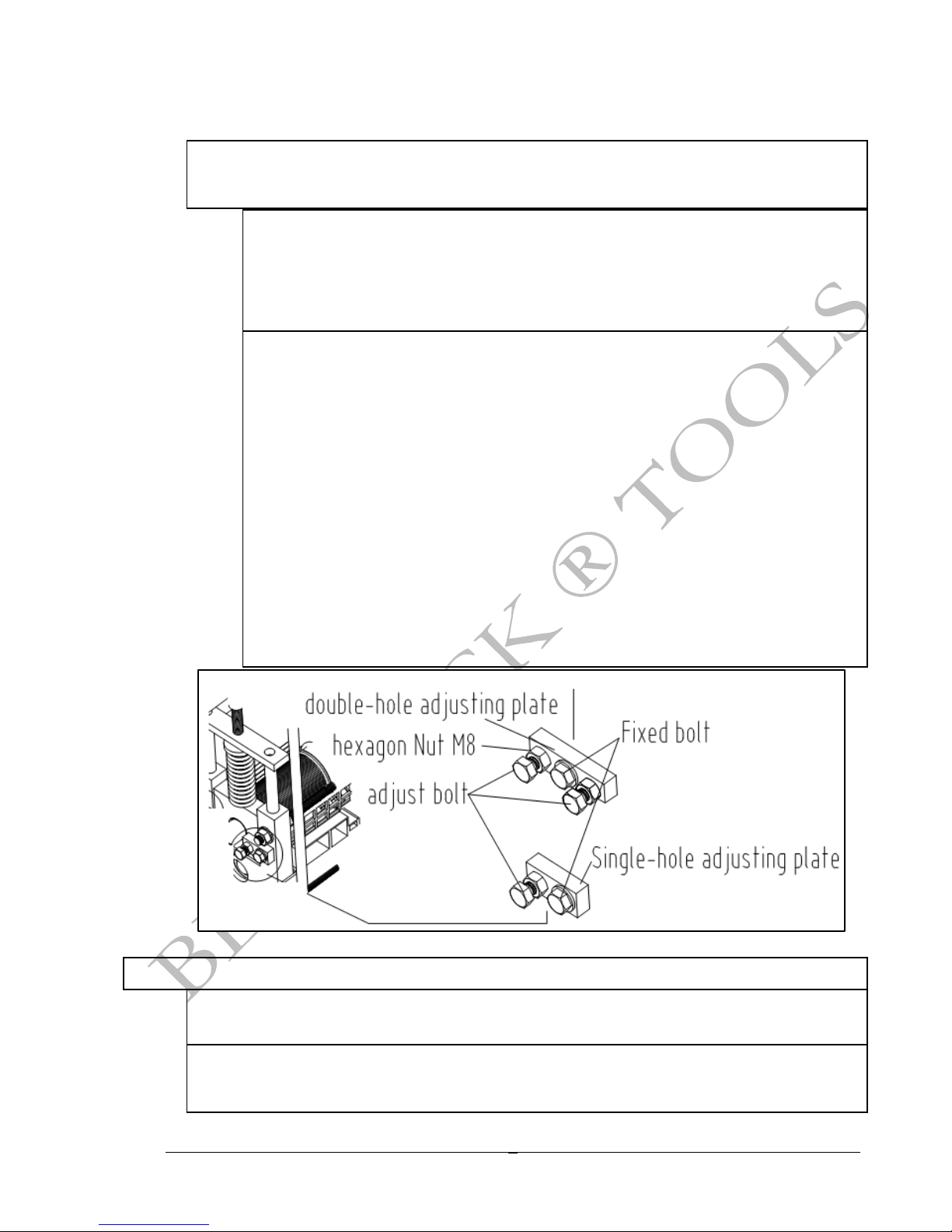
ØThe secondary adjusting point on this machine are the side centering bolts. These
are the bolts with lock nuts on them located on the side of both bearing housings that
adjust the top cutting assembly from right to left.
oIt is generally not recommended to adjust these bolts unless the smallest
channel cutting blades are not centered in the cutting channel. To access
this, the user will look down the smallest left channels and visually gauge if
the blades are centered. If these centering bolts have too much play in them,
the entire cutting channel can move too much from right to left during running
wire.
oIf the blades are not centered or have too much play, they can be adjusted.
You really only need the entire cutter assembly (from bearing housing on
right to bearing housing on left) to have about 1/16” of play. Essentially, you
just need enough room for the centering bolts to allow the entire assembly to
raise when a piece of wire goes through the channel and pushes up the entire
cutter assembly. It is generally recommended to set the centering bolts by
unscrewing the centering bolts on both sides of the assembly a few
turns. Then looking down the left (small wire) cutting channels, tap the
housing right or left to get the blades in the center of the channel. Screw the
bolts in evenly from both sides (right and left bolts). Be careful here not to
move the entire assembly. When they are tight against the housings, take
another look down the left channel guides making sure the cutters are still in
the center of the channel groove. If they are not, readjust. Next loosen the
centering bolts by about ½a turn on both the right and left side. This leaves
just enough of an air gap to allow the cutting assembly to raise, but not travel
too much from right to left. Next tighten the lock nuts. Make sure not to
tighten or loosen the centering bolt on this step by using another wrench to
ensure it doesn’t spin.
PROCESSING WIRE
ØThere is a wire guide in front of the main shaft and blade shaft where the cables will
be manually inserted. See wire input guide diagram below for a general
understanding of what wires can go in certain cutting channels.
ØThe wire input guide will be used as a general starting point for processing wire.
Before processing, it is recommended to collect similar wire types to assist in wire
processing efficiency.

MWS-83MD
7
ØSelecting the correct input to run the wire through can take some time and
experience. The general rule is to start in a much larger wire guide than the wire in
question, run the wire, check the wire. If not cut, step down to a smaller input guide
and try it again. It is a general misconception that the user should put a wire in the
hole that is the exact same size of the wire. This is rarely the case. After a while the
user will know from experience which guide is right for certain wire types.
WIRE TYPE GUIDE
ØSheathed flat cable: ≤0.55” (14mm) x 0.31” (8mm) WxH
ØTwisted flat cable: ≤0.31” (8mm) x 0.23” (6mm) WxH
ØSingle-core cable: Dia. Φ0.07” (2mm) ~ Φ1” (25mm)
Round cable Sheathed flat cable Twisted flat cable Single-core cable
WIRE GUIDE DIAGRAM
RUNNING WIRE
ØDo all pre-operational and operational safety checks from Chapter 1.
ØSecuring the machine and installing the hand-wheel and hand-crank or using a user
supplied chuck type drill to the 12mm drill shaft.
ØHave your wires ready to process, by separating them by type and cutting them into
3-4’ lengths.
ØSelect a wire to strip.
ØDecide on which guide is the correct guide input.

MWS-83MD
8
ØIf using the hand crank- run the wire through while turning the hand-crank until the
wire is all the way through. You can also partially run the wire through with the hand-
crank and go to the output of the machine and pull the wire through the remainder of
the way.
ØIf using a drill and the drill shaft, slowly turn the drill forward causing the drill to turn
the lower roller shaft. After a comfortable speed is reached (slowly enough to have
power over the drill and control inputting wire safely) put a piece of wire in the
machine. Be cautious in the beginning to only use your drill as slowly as possible to
get a feel for how quickly the drill pulls the wire in. When in doubt, take your finger
off the power of your drill and regroup.
oIf the wire did not cut through the complete jacket, run it through again
through a smaller channel.
oIf there are no smaller channels, tighten the T-bolt half/full turn closest to the
channel you’re attempting to use.
ØSeparate the wire from the jacket
oOn smaller wire this will be done by pulling the wire out of the jacket.
oFor larger wires with thicker jackets, if you are not able to pull the wire out of
the jacket, you may need to run the wire through again cutting into the
opposite side of the wire jacket.

MWS-83MD
9
Troubleshooting
Problem
Solution
Wires get jammed in the
machine
There are a few possible fixes for this:
1: Loosen the top hand cranks to take pressure off springs to allow more room for
the springs to depress.
2: Check to make sure you are running the wire through the right channel. This
takes some time to figure out. Be patient when clearing the machine. Try the step
down method. Start in a larger hole than you think. Work your way down to a
smaller hole until ideal cut is made.
3: Only use the 1st two channels for running Romex®. They have the Rectangular
Guides.
4: The jacket on the wire you are trying to run is too thick. This machine will not
strip some wires where the jacket is too thick or the materials are too dense, such
as some underground plastics.
For smaller wire, the cut
in the wire jacket is not
in the center of the wire
The side adjustments could be out of alignment on the cutter rollers. The cutter
rollers on the top of the cutting assembly can adjust right to left. The cutting blades
should be centered in the middle of every roller. You can look down the middle of
every roller from front and back of the machine to see if the cutters are in the center.
If they are not, you can adjust the top cutter and rollers by adjusting the side bolts
(with the lock nut) to slightly shift the cutter/roller. Make sure you do not tighten the
bolts too much so the top cutter/roller assembly cannot raise and lower as wire
passes through. Think of these bolts as side stops only, just to keep the assembly
inline, so leave about 1mm gap in-between bolt and cutter/rollers.
The machine is
excessively loud and
makes grinding noise
These machines are generally on the noisier side as they use a gear drive system.
Firstly make sure the gears are greased. This can help with the noise. You can also
check the side adjustments as they could be out of alignment on the cutter rollers.
The cutter rollers on the top of the cutting assembly can adjust right to left/right.
The cutting blades should be centered in the middle of every roller especially those
on the left. You can look down the middle of every roller from front and back of the
machine to see if the cutters are in the center. If they are not, you can adjust the top
cutter and rollers by adjusting the side bolts (with the lock nut) to slightly shift the
cutter/roller. Make sure you do not tighten the bolts too much so the top
cutter/roller assembly cannot raise and lower as wire passes through. Think of
these bolts as side stops only, just to keep the assembly inline, so leave about 1mm
gap in between bolt and cutter/rollers.
The machine is not
cutting through the
entire jacket
Increase the tension on the top hand cranks. It is also possible that either you are
cutting wire that has too thick of a wire jacket or too dense a jacket. These jackets
may not be able to cut with this machine
Chapter
4

MWS-83MD
10
Maintenance
ØKeep machine clean and free of debris.
ØGrease internal gears with red grease or Molybdenum grease as needed.
ØSpray antirust oil on blades and blade shaft as needed.
ØInspect blades occasionally to ensure they are sharp for optimal cutting.
Changing Blades
1. Remove upper cutter/roller tensioners and the springs below them.
2. Use 11/16” socket to remove top bolts, and the spacers below them.
3. Take the top guard off.
4. Take the cutter assembly out.
5. Use adjustable large puller to pull bearing housing off the cutter assembly.
6. Use puller to pull bearing from cutter assembly. Make sure to mark the bearings position on
the steel rod to assure the correct position upon reassembly.
Chapter
5

MWS-83MD
11
7. Unscrew spanner nut clockwise. If you do not have a spanner nut wrench, it is possible to
use a pair of vice grips.
8. MAKE SURE YOU MARK THE SPACERS 1 THROUGH 5 (OR 1 THROUGH 4 FOR THE TOP
ASSEMBLY), SO THAT THEY GO BACK ON IN THE SAME ORDER THAT YOU TOOK THEM
OFF.
9. Blades are ready to come off and be replaced.

MWS-83MD
12
10. When re-assembling put the bearing back into the bearing housing before attaching the
housing to the cutter/roller.
11. Follow all other steps in reverse order to reassemble.

MWS-83MD
13
Parts List
Number&
Code&Number&
QTY&
Material&
Name&
1&&
MWS-83MD-0001&
2""
HT200&
Siding&board&
2&&
MWS-83MD-0002&
2""
45#&
Gear&
3&&
MWS-83MD-0003&
1&&
45#&
Main&shaft&
4&&
MWS-83MD-0004&
1&&
Spacer&
5&&
MWS-83MD-0005&
9&&
65Mn&
Blade&
6&&
GB/T5780-2000&
4"
A3&
Hex&nut&M10x90&
7&&
MWS-83MD-0006&
2""
&&
T&shape&handle&
8&&
GB/T62-1988&
2""
ZL102&
Wing&nut&
9&&
GB/T95-1985&
16&&
&&
Washer&Φ10&
10&&
MWS-83MD-0007&
1&&
Top&shield&
11&&
MWS-83MD-0008&
2""
A3&
Iron&plate&
12&&
MWS-83MD-0009&
2""
HT200&
Pressure&cap&
13&&
MWS-83MD-0010&
2""
65Mn&
Big&spring&
14&&
MWS-83MD-0011&
2""
65Mn&
Small&spring&
15&&
MWS-83MD-0012&
4"
Support&tube&
16&&
MWS-83MD-0013&
1&&
Shovel&
17&&
MWS-83MD-001/f&
1&&
45#&
Blade&shaft&
19&&
GB/T5781-2000&
4"
A3&
Hex&bolt&M8x30&
19&&
MWS-83MD-0015&
4"
A3&
Stopper&plate&-2&holes&
20&&
GB/T5781-2000&
6&&
A3&
Hex&bolt&M8x30&
21&&
GB/T95-1985&
6&&
A3&
Washer&Φ8&
22&&
GB/T41-2000&
6&&
A3&
Hex&nuts&M8&
23&&
GB/T41-2000&
12&&
A3&
Hex&nuts&M10&
24&&
GB/T93-1987&
6&&
A3&
Spring&washer&Φ10&
25&&
GB/T95-1985&
12"
A3&
Washer&Φ10&
26&&
MWS-83MD-0016&
2""
30x30
Angle&iron&base&
27&&
MWS-83MD-0017&
3&&
A3&
Tie&rod&m10&
28&&
MWS-83MD-0018&
1"
Feed&inlet&
29&
MWS-83MD-0019&
2"
A3&
Fasten&bar&
Chapter
6

MWS-83MD
14
Breakdown View
Table of contents


