Blueview BV-3100 User manual

BV-3100 Mobile Acoustic Underwater Vision® System
!"#$%"
#&%%'(&$&"

BlueView Technologies has made every effort to ensure the accuracy and completeness of this
document; however, because ongoing development efforts are made to continually improve the
capabilities of our products, we cannot guarantee the accuracy of the contents of this document. We
disclaim liability for errors, omissions, or future changes herein. For the most up to date information
read the help.txt file in the roViewerE software.
Copyright © 2003-2009 BlueView Technologies Corp. All rights reserved. No part of this publication
may be copied, reproduced, or translated, without the prior written consent of BlueView Technologies.
No part of this publication may be stored or transmitted in any electronic form without the prior
consent of BlueView Technologies. Any unauthorized use is a violation of copyright laws.
Warning! This product contains lead, a chemical known to the state of California to
cause cancer, birth defects and other reproductive harm. Handling and/or opening this
unit may result in exposure to lead, in the form of solder.
Warning! Disassembly and repair of this electronic unit should only be performed by
authori ed service personnel. Any modification of the serial number or attempt to repair
the original equipment or accessories by unauthori ed individuals will void the
warranty.
Warning! Changes or modifications to this unit not expressly approved by the party
responsible for compliance may void the any product warranty. This includes the
installation an operation of any not approved software .
Warranty Information
The BV-3100 is backed by a standard 12-month parts and labor warranty policy.
For more information on warranty and/or maintenance issues please call BlueView Technologies at
206.545.7260.
BV-3100 User’s Handbook 15 April 2009
Page 1

IMPORTANT SAFEGUARDS
When using ele tri al produ ts, basi safety pre autions should always be followed, in luding the
following:
READ ALL INSTRUCTIONS BEFORE USING
DANGER – To reduce the risk of electrocution:
" Always unplug the BV-3100 control box immediately after using.
" Do not place or store the control box where it can easily fall or be pulled into water.
)" If the box does fall in the water, unplug before retrieving.
WARNING – To reduce the risk of burns, electrocution, fire, or injury to persons:
1. Use this sonar only for its intended use as described in this manual. Do not use attachments not recommended by BlueView
Technologies.
2. Never operate this product if it has a damaged cord or plug, if it is not working properly, if it has been dropped or damaged, or
if the control box has been dropped into water.
3. Keep cords away from heated surfaces.
4. Connect this product to a properly grounded outlet only. See grounding instructions.
SAVE THESE INSTRUCTIONS
GROUNDING INSTRUCTIONS
This product should be grounded. In the event of an electrical short circuit, grounding reduces the risk of electric shock by providing an
escape wire for the electric current. The BV-3100 control box is equipped with a cord having a grounding wire with a grounding plug. The
plug must be plugged into an outlet that is properly installed and grounded.
DANGER – Improper use of the grounding plug can result in a risk of electric shock.
If repair or replacement of the cord or plug is necessary, do not connect the grounding wire to either flat blade terminal. The wire
with insulation having an outer surface that is green with or without yellow stripes is the grounding wire.
Check with a qualified electrician or serviceman if the grounding instructions are not completely understood, or if in doubt as to
whether the product is properly grounded.
This product is factory equipped with a specific electric cord and plug to permit connection to a proper electric circuit. Make sure
that the product is connected to an outlet having the same configuration as the plug. No adapter should be used with this product. Do not
modify the plug provided—if it will not fit the outlet, have the proper outlet installed by a qualified electrician. If the product must be
reconnected for use on a different type of electric circuit, the reconnection should be made by qualified service personnel.
If it is necessary to use an extension cord, use only a three wire extension cord that has a three-blade grounding plug, and a
three-slot receptacle that will accept the plug on the product. Replace or repair a damaged cord.
BV-3100 User’s Handbook 15 April 2009
Page 2

(*
*&+ """"""""""""""""""""""""""""""""""""""""""""""""""""""""""""""""""""""""""""""" ,
-$$""""""""""""""""""""""""""""""""""""""""""""""""""""""""""""""""""""""""""""""""""""""""""""""""""""""""""""""""""""""""""""""""""""""",
.%%'*"""""""""""""""""""""""""""""""""""""""""""""""""""""""""""""""""""""""""""""""""""""""""""""""""""""""""",
*&/'.0*& """"""""""""""""""""""""""""""""""" 1
2"""""""""""""""""""""""""""""""""""""""""""""""""""""""""""""""""""""""""""""""""""""""""""""""""""""""""""""""""""""""""""""""1
.34.567"""""""""""""""""""""""""""""""""""""""""""""""""""""""""""""""""""""""""""""""""""""""""""
*&))! """""""""""""""""""""""""""""""""""""""""""""""""""""""""""""
# """""""""""""""""""""""""""""""""""""""""""""""""""""""""""""""""""""""""""""""""""""""""""""""""""""""""""""""""""""
2"""""""""""""""""""""""""""""""""""""""""""""""""""""""""""""""""""""""""""""""""""""""""""""""""""""""""""""""""""""""""""""""
!.67 """""""""""""""""""""""""""""""""""""""""""""""""""""""""""""""""""""""""""""""""""""""""""""""""
8** """"""""""""""""""""""""""""""""""""""""""""""""""""""""""""""""""""""""""""""""""""""""""""""""""""""""""""" ,
*( """""""""""""""""""""""""""""""""""""""""""""""""""""""""""""""""""""""""""""""""""""""""""""""""""""""""""" 1
39-& """""""""""""""""""""""""""""""""""""""""""""""""""""""""""""""""""""""""""""""""""""""""""""""""""""""""""
Positioning controls ............................................................................................. 1
Pre-defined position buttons ................................................................................. 1
Numeric ‘tilt’ read-out ......................................................................................... 1
Numeric ‘pan’ readout ......................................................................................... 17
Target Depth’ selector ......................................................................................... 17
.0'%"""""""""""""""""""""""""""""""""""""""""""""""""""""""""""""""""""""""""""""""""""""""""""""""""""""""""""""""""""""
Pole case ........................................................................................................... 17
*&, """"""""""""""""""""""""""""""""""""""""""""""""""""""""""""""""""""""""""""""""""""""""""""""""""""" :
#&&%7#.&( """""""""""""""""""""""""""""""""""""""""""""""""""""""""""""""""""""""""""""""""""""""
#&&%7* """""""""""""""""""""""""""""""""""""""""""""""""""""""""""""""""""""""""""""""""""""""""""""""""
BV-3100 User’s Handbook 15 April 2009
Page 3

Chapter 1 Welcome
Overview
The BlueView BV-3100 Mobile Acoustic Underwater Vision® System is an inte rated
solution for operatin a boat mountable BlueView sonar mounted on a di ital pan
and tilt unit. The pole mounted sonar and Pan & Tilt connects with a sin le cable to
the BV-3100 control box, which connects to a PC via USB and Ethernet. The BV-
3100 system is airline checkable lu a e.
Standard Package Contents
Please note that special orders may include variations to this list. If you are not
sure or feel your packa e may be missin items, please contact BlueView at
206.545.7260.
Component
Sonar Module
Hard Shell Transport Case
Sonar, Pan & Tilt (SPT) Junction Box
Pan and Tilt Pole with 50 ft Cable Assembly
Transom Mount Assembly
7 ft. Ethernet Cable
Ru ed USB Cable
Power Cable
BV-3100 Quickstart Guide
BV-3100 Installation and Operation Manual
ProViewer Software CD
Sonar User’s Handbook
Hex Driver
Screw Kit
BV-3100 User’s Handbook 15 April 2009
Page 4

Chapter 2 Get to know the System Components
To familiarize yourself with the BV-3100 system, please review the identifications
charts below.
Mounting Pole
Sonar Mounting Pole Connectors
BV-3100 User’s Handbook 15 April 2009
Page 5
Main Pole Connector: This connector provides power
and data from the Sonar Pan & Tilt Junction Box (SPT) to
both the sonar and pan/tilt
Sonar Cable: This connector provides power and data
from the SPT to the sonar
Pan and Tilt connector: This connector provides
power and control from the SPT to the pan/tilt unit
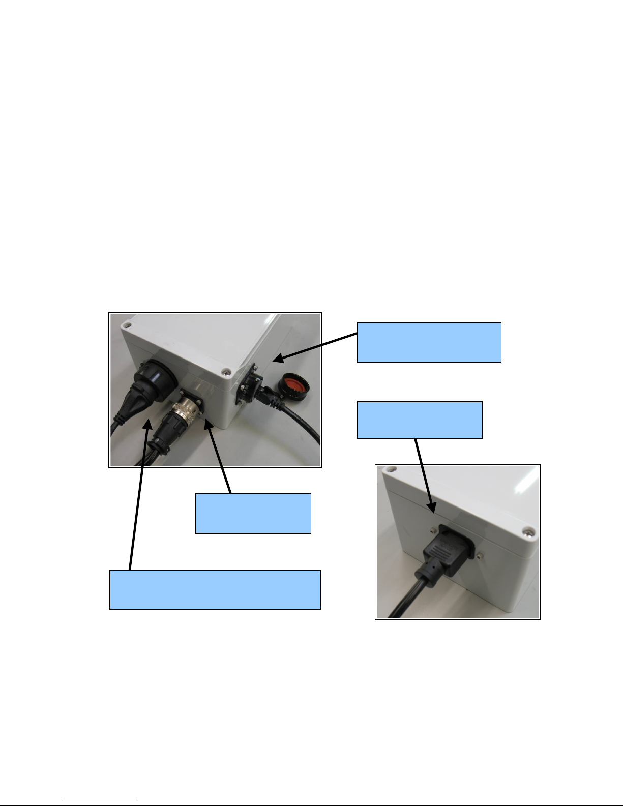
Sonar Pan & Tilt (SPT) Junction Box
The SPT junction box contains a power supply, a USB to RS-485 Converter and a
flash memory drive. The power supply provides power to both the pan and tilt unit
and sonar. The converter adds a COM port to the PC so the PC can communicate
with the pan and tilt via a USB port The flash memory contains the necessary
drivers for the USB to COM port converter. The Ethernet port on the control box
provides communication with the sonar. The SPT box can handle input AC power
between 110 and 240 volts.
BV-3100 User’s Handbook 15 April 2009
Page 6
;*
.*
#*!
,#*
.%
39
9.*;%%%9.
<$%39
*
SPT Bo Connectors

Chapter 3 BV-3100 Installation
After verifyin that all necessary components are present, you are ready to be in
inte ration of the BV-3100.
Assem ling the Pole
The followin instructions will walk you throu h all steps necessary to assemble the
pole, mount the sonar, and connect all required cablin .
1. Remove the pole unit from shippin case.
2. Place the top and bottom pole pieces end to end and pull the excess cable
throu h the top of the pole.
3. Rotate one of the pole se ments till the ali nment notches are adjacent to
each other.
4. Attach the lower section to the upper usin the provided cap screws. Insert
the bolt first throu h the unthreaded upper flan e and screw into the
threaded lower flan e.
BV-3100 User’s Handbook 15 April 2009
Page 7
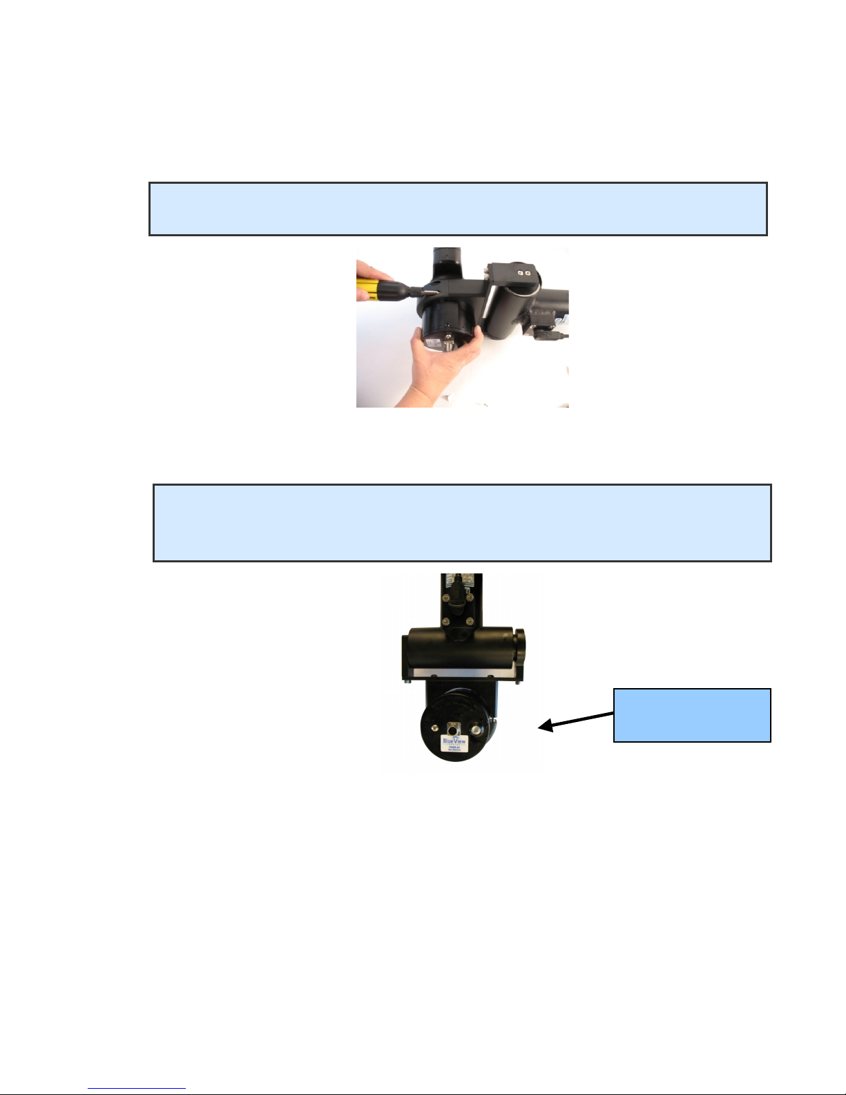
5. Attach the sonar into the sonar clamp by loosenin the four cap screws,
slidin in the sonar and reti htenin the four cap screws.
BV-3100 User’s Handbook 15 April 2009
Page 8
NOTE: The sonar is inserted into the clamp such that its connector is on the same side
as the Pan & Tilt connector.
NOTE: Use the stickers and connector placement on the rear end cap of the
sonar to determine the up-down orientation of the sonar. If the sonar is
inverted, be sure to select the “inverted” option in ProViewer’s settin s.
!$%=%
#

6. Connect the pan/tilt cable to the pan/tilt connector.
7. Connect the sonar cable to the sonar connector.
Pole Mounting
1. Securely attach the transom mount assembly to a fixed structure. The mountin
holes are sized for .25” bolts.
2. Place the pole into the clamp and close the clamp by ti htenin the threaded
knob.
3. Rotate the pole in the mount so that the sonar, when set to the ‘home position,’
points in the desired direction.
BV-3100 User’s Handbook 15 April 2009
Page 9
NOTE: It is the user’s responsibility to insure the pole mount is secured in a way that
will support the pole assembly.
NOTE: Do not let go of the pole assembly until the clamp is closed and the threads
have fully engaged.

Installing the SPT Junction Box
The SPT junction box contains a USB to RS-485 converter plus a USB flash drive.
The converter will add a COM port to the PC for communicatin with the pan and tilt.
The drivers for the converter need to be installed onto the PC. These drivers are
located on the USB flash memory drive located in the control box.
There are two drivers to install: one is for a “USB Serial Converter”, and the other
is for a “USB Serial Port.”
1. Connect the USB port on the control box to an available USB port on the PC. The
“Found New Hardware Wizard” will uide you throu h the installation process.
BV-3100 User’s Handbook 15 April 2009
Page 10
NOTE: Do not close the second “Found New Hardware Wizard” window while
installin the driver.
NOTE: For Windows Vista, disconnect your PC from the internet before installin
drivers; otherwise, Windows Vista will search for and install the drivers automatically
from Windows Updates and cause errors. The instructions below are for Windows XP.
Installation for Windows Vista may vary from the instructions below.
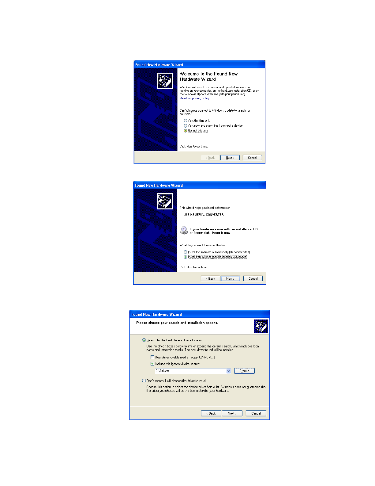
2. First, the USB Serial Converter driver will install. Select “No, not this time” and
click “Next.”
3. Select “Install from a list or specific location” and click “Next.”
4. Click “Browse” and navi ate to the flash drive. Select the folder on that drive.
Click “Next.”
BV-3100 User’s Handbook 15 April 2009
Page 11

5. The driver will install. Click “Finish” to complete the installation of the first driver.
6. Next the USB Serial Porter Driver will be installed. Select “No, not this time” and
click “Next.”
7. Select “Install from a list or specific location” and click “Next.”
BV-3100 User’s Handbook 15 April 2009
Page 12

8. Click “Browse” and navi ate to the flash drive. Select the folder on that drive.
Click “Next.”
9. The driver will install. Click “Finish” to complete the installation of the second
driver. The PC is now ready to control the pan and tilt.
BV-3100 User’s Handbook 15 April 2009
Page 13
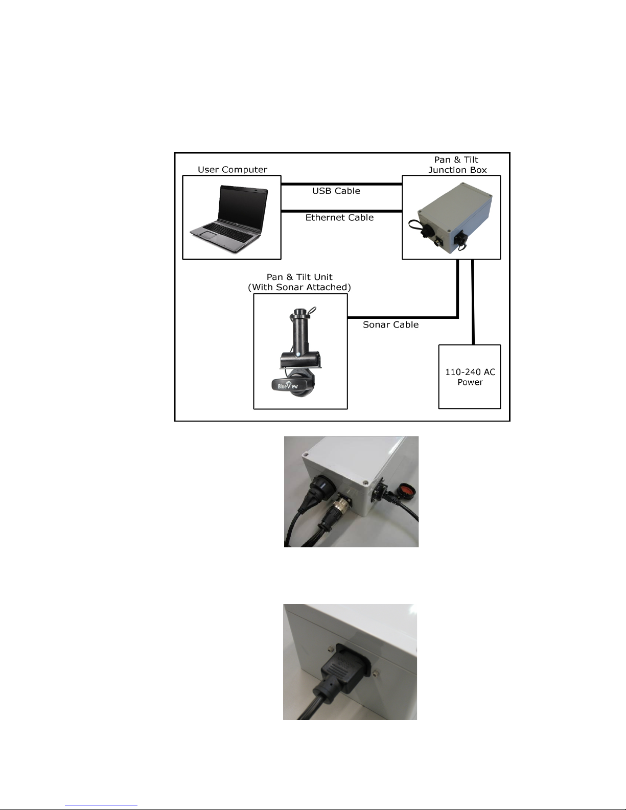
Final Ca le Connections
" Connect the sonar and Pan & Tilt unit to the control box. Connect the Ethernet
cable to the control box, then to an available network connection port on the
PC. Verify that all connections in the dia ram below have been made.
2. Connect the power cable to the control box. Connect the opposite end to a
suitable AC power outlet. All necessary connections have now been made.
BV-3100 User’s Handbook 15 April 2009
Page 14

ProViewer Configuration
1. Install the ProViewer software with the CD included with your ProViewer User’s
Manual. Run the setup, clickin “Do Not Block” if prompted.
2. Launch ProViewer and select “Settin s” from the “File” menu.
3. Click the “Pan & Tilt” icon on the left menu.
4. Click the “Pan Installed” and “Tilt Installed” boxes. Confirm that the ali nment
(inverted or upri ht) is properly indicated, and then click “Detect.” The software will
automatically detect the Pan & Tilt throu h the COM Port.
The Pro iewer software is now properly configured.
BV-3100 User’s Handbook 15 April 2009
Page 15
NOTE: ! 0 0 manually assign *-2 &
"> &&& *-2 & (% +% ?<$
2"@ >' ( & ?9. . 4*-2775@ % &
$">/8A.AB%&&&*-2&(
%&%">?<"@
Pan & Tilt Unit Operation
As explained below, the ProViewer software pan/tilt controls break down into 3
roups: positionin , pre-set positions, and numeric read outs.
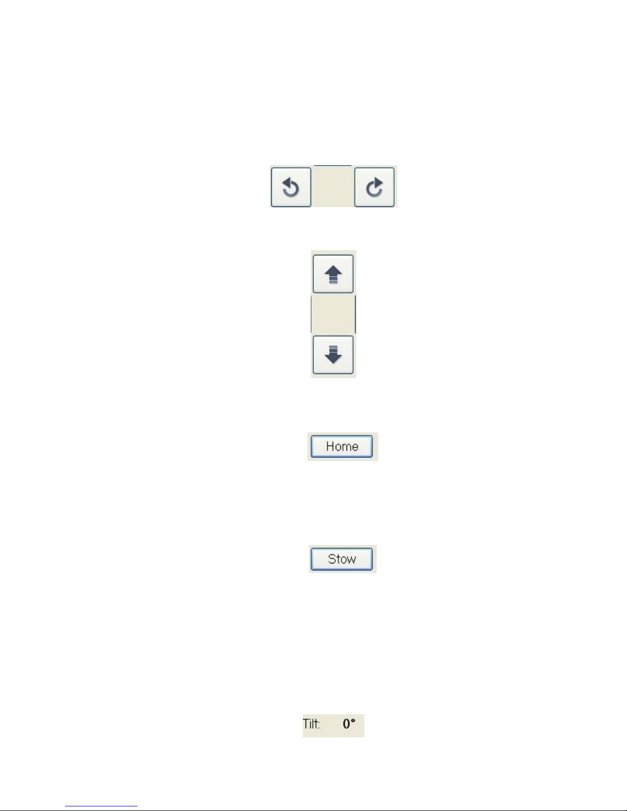
Positioning controls
Pan (rotate the sonar left or ri ht) by clickin the buttons shown above.
Tilt (tip the sonar towards the surface or bottom) by clickin the buttons show
above.
Pre-defined position uttons
Clickin the ‘home’ button will cause the pan/tilt to automatically move to the
home position. The home position is factory-set to 0 de rees pan and 0 de rees
tilt. You can specify the home position under the pan/tilt section of the ‘settin s’
window under the ‘file’ menu.
Clickin the ‘stow’ button will cause the pan/tilt to automatically move to the
stow position. The stow position is factory set to 0 de rees pan and 0 de rees
tilt. You can specify the stow position under the pan/tilt section of the ‘settin s’
window under the ‘file’ menu.
Numeric ‘tilt’ read-out
BV-3100 User’s Handbook 15 April 2009
Page 16
0 de rees indicates the sonar is pointed perpendicular to the pole. In calm
seas with a vertically mounted pole, this will be parallel to the surface of
the water.
The unit can tilt upwards (ne ative tilt) approximately 79 de rees
The unit can tilt downwards (positive tilt) approximately 70 de rees.
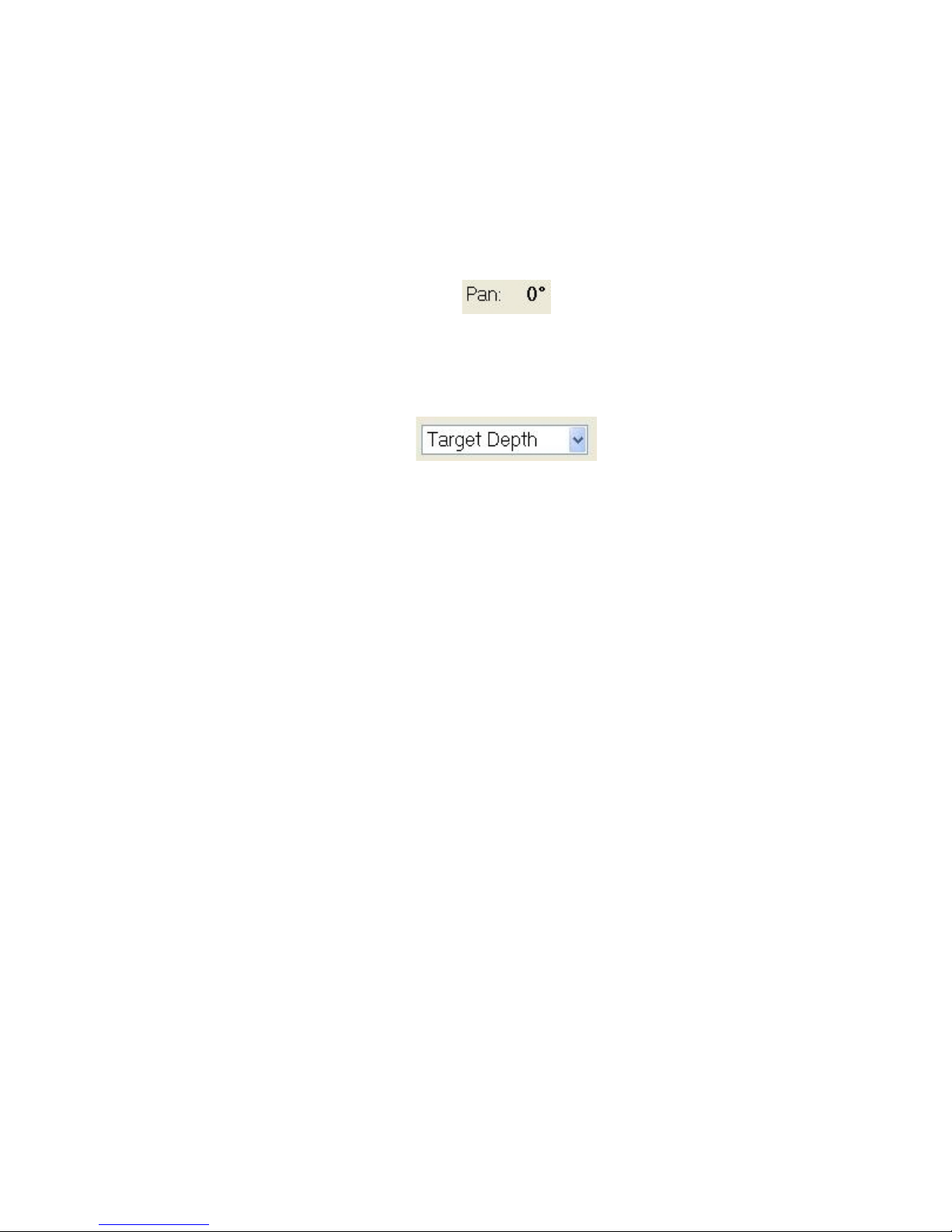
Numeric ‘pan’ readout
0 de rees is the center of movement.
The unit can pan clockwise (positive rotation) about 179 de rees.
The unit can pan counter clockwise (ne ative rotation) about 179 de rees
Target Depth’ selector
Selectin one of the tar et depths will cause the sonar start/stop ran es and tilt
an le to move to pre-defined values.
BV-3100 User’s Handbook 15 April 2009
Page 17
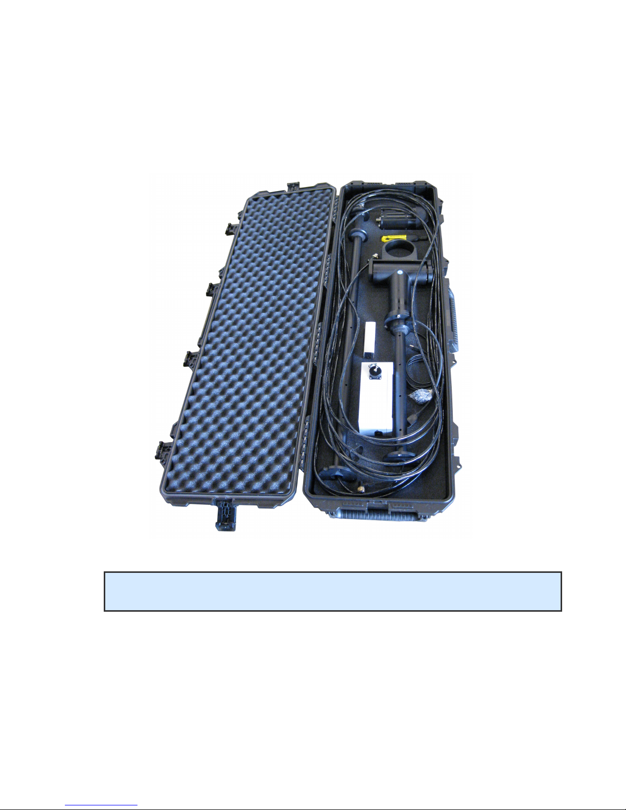
System Breakdown
Pole case
Proper system breakdown of the BV-3100 requires only that the AC power and pole
cable be disconnected from the console, rinse the pole and sonar with fresh water
and return to their respective positions in the carryin case, as shown.
BV-3100 User’s Handbook 15 April 2009
Page 18
NOTE: Care should be taken to ensure cables are positioned not to crimp or damage
pole components or the cable while shutting the case.

Chapter 4 Trou leshooting
+C00C$&0)0"!(&%
$0&(0%&0$"
Symptoms Possible ause Resolution
(%
0(%
%"
.67#*&*%
&%$#*
;&%
&%$#*
.% (0&&%
.67"
(0%
"
(0;%
.67%*"
.D% ;&0
%0 %%&&0
*!%% 80
*C!
%%B.2'
":""B11"11"11"
.7&%& 9&#*&.
67(%%
"
*%
39
39%" (0&&%
.67"
(0%
"
(0;%
.67%*"
9.E.,:1%$%
&&0
9%$"
*-20%0
.?*(@
("
BC$
%%%
2% (0F
0F
.(&% G&
%0(
&"G
%0(
&"
If your system is still not functionin properly, contact BlueView’s technical
support at 206-812-3010 or email us at [email protected]
BV-3100 User’s Handbook 15 April 2009
Page 19
Table of contents
Popular Sonar manuals by other brands


Garmin
Garmin Panoptix PS22-TR installation instructions

Marcum Technologies
Marcum Technologies Digital Sonar LX-i owner's manual

Simrad
Simrad SP60 - REV D Operator's manual

L3 comminications
L3 comminications SERIES 5000 Operation and maintenance manual

Eagle
Eagle Strata 128 Portable Install and operation instructions

Furuno
Furuno DS-60 Operator's manual


