blupura WALL Specification sheet

1
6
0
3
2
7
1
6
0
7
E
N
WALL
U
s
e
&
M
a
i
n
t
e
n
a
n
c
e
M
a
n
u
a
l


3
Index
• BEFORE INSTALLING THE WATER COOLER 4
• RECOMMENDATIONS FOR SAFEGUARDING THE ENVIRONMENT 5
• DECLARATION OF CONFORMITY 6
• ASSOCIATIONS 7
• INTERNATIONAL AWARDS 7
• PRECAUTIONS AND GENERAL RECOMMENDATIONS 8
• DESCRIPTION OF THE UNIT 9
• DESCRIPTION OF THE KEYBOARD 12
• TECHNICAL FEATURES – TECHNICAL DATA PLATE 13
• INSTALLATION 16
• FILTRATION (OPTIONAL) 21
• SANITIZATION – NOTES 22
• ORDINARY MAINTENANCE 23
• SERVICE HISTORY 24
• WARRANTY CONDITIONS 25

4
Before installing the water cooler
Congratulations for choosing a BLUPURA product.
We have designed and manufactured this product with great care to ensure that
it will dispense water of the highest quality.
In order to get the most out of your water cooler, please read the instructions in
this manual and retain the manual for future reference.
5
Recommendations for safeguarding the environment
Packaging materials
The packaging materials are 100% recyclable.
Please follow the local guidelines on waste
disposal. For safety reasons keep the packaging
material out of the reach and sight of children.
Scrappage
The water cooler is made using recyclable material.
This unit is marked in compliance with European Directive 2002/96/EC
on Waste Electrical and Electronic Equipment (WEEE). By ensuring that
the product is scrapped correctly, you are helping to prevent potential
negative consequences for the environment and for health. The symbol
on the unit indicates that the product should not be treated as domestic waste
but should be taken to a dedicated recycling centre for electrical and electronic
equipment. Immediately prior to scrapping, cut off the power cable.
For more information on the treatment, recovery and recycling of this product,
please contact the appropriate local office, the waste disposal service or the
reseller from which the product was purchased.
6
Declaration of conformity
Materials compliant for contact with drinking water
This unit is intended for the dispensing of drinking water, and so the materials
that enter into direct contact with water meet the criteria for food-grade
components pursuant to the current legislation. In addition, the unit is
manufactured in compliance with Italian Ministerial Decrees 174 of 06/04/2004
and 25 of 07/02/2012.
Electrical safety
This water cooler is designed, manufactured and marketed in compliance with:
• the safety objectives of the Low Voltage Directive 2006/95/EC;
• the protection requirements of the Electromagnetic Compatibility Directive
2004/108/EC.
The electrical safety of the product is ensured only when it is properly connected
to an efficient, legally compliant grounding circuit.
D.M. 174
1
0
0
%
M
A
D
E
I
N
I
T
A
L
Y
C
E
R
T
I
F
I
C
A
T
E
I
T
P
I
rosso032 c
UNI EN ISO 9001:2015
UNI EN ISO 14001:2015
7
Associations
International Awards
2015 - BEST PROMOTION OF HEALTH AND HYDRATION
EUROPEAN AQUA AWARDS 2015, ROME
2015 - BEST ENVIRONMENTAL PRACTICE/GREEN INITIATIVE
EUROPEAN AQUA AWARDS 2015, ROME
2014 - BEST PROMOTION OF HEALTH AND HYDRATION
EUROPEAN AQUA AWARDS 2014, BUDAPEST
2013 - BEST PRODUCT INNOVATION
EUROPEAN AQUA AWARDS 2013, BERLIN
2012 - BEST ENVIRONMENTALLY FRIENDLY PRACTICE
EUROPEAN AQUA AWARDS 2012, ISTANBUL
2011 - BEST PRODUCT DESIGN/INNOVATION
EUROPEAN AQUA AWARDS 2011, ODESSA
2010 - BEST ENVIRONMENTALLY FRIENDLY PRACTICE
EUROPEAN AQUA AWARD 2010, PRAGUE

8
Precautions and general recommendations
Always connect the unit to a water main that supplies
drinking water only.
Before each installation, the unit must be sanitized by
an authorized technician.
After installation, ensure that the unit is not resting on
the power cable.
Check that the unit is level and that it is resting on a wall
with sufficient load-bearing capacity, in an environment
that is suitable for its dimensions and its use.
Before any maintenance or cleaning operation is carried out, remove the plug
from the socket or disconnect the power supply.
Ensure that the product is not sited close to sources of heat.
Install the product in a clean, dry, well-ventilated environment. The water cooler is
designed to function in environments with a temperature range of between 5°C
and 32°C - Climate Class N.
The unit is not intended for use by children.
If the power cable is damaged, it must be replaced by the manufacturer, by
its technical support service or by a qualified technician. Do not use extension
cables or multi-plugs.
Ensure that it is possible to disconnect the power supply either by removing the
plug or via a two-pole circuit-breaker placed upstream of the plug.
Check that the voltage shown on the serial number plate corresponds to the
voltage being supplied at the installation site.
The unit must not be cleaned with a water jet. Do not position other electrical
equipment in the immediate vicinity of the water cooler.
Turn off the main water inlet tap if the unit is not to be used for a long period.
Keep the areas surrounding the unit dry to avoid the risk of people slipping.
This appliance is not intended for use by persons (including children) with
reduced physical, sensory or mental capabilities, or lack of experience
and knowledge, unless they have been given supervision or instruction
concerning use of the appliance by a person responsible for their safety.
Children should be supervised to ensure that they do not play with the
appliance .
The Appliance shall be protected by a ground-fault circuit interrupter.

9
Description of the unit
WALL - the innovative wall-housed water cooler with a great design, for
single or multiple connection.
• A modern design using natural materials, such as stainless
steel and aluminium.
• Elegant and practical for office spaces, homes, residences,
high-class condominiums and hotels.
• Perfect also for schools, hospitals and in any setting where, for
security reason or noise, floor standing water-coolers cannot be
installed.
• 1 or 2 stainless steel push buttons.
• Can be fitted to any type of undercounter water-coolers.
Visit the website www.blupura.com to view our product range.
10
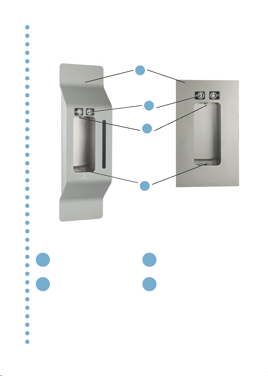
Front view
Front cover
1
Drip tray with grid
4
Stainless steel push buttons
2
Dispensing nozzle
3
1
2
3
4
11
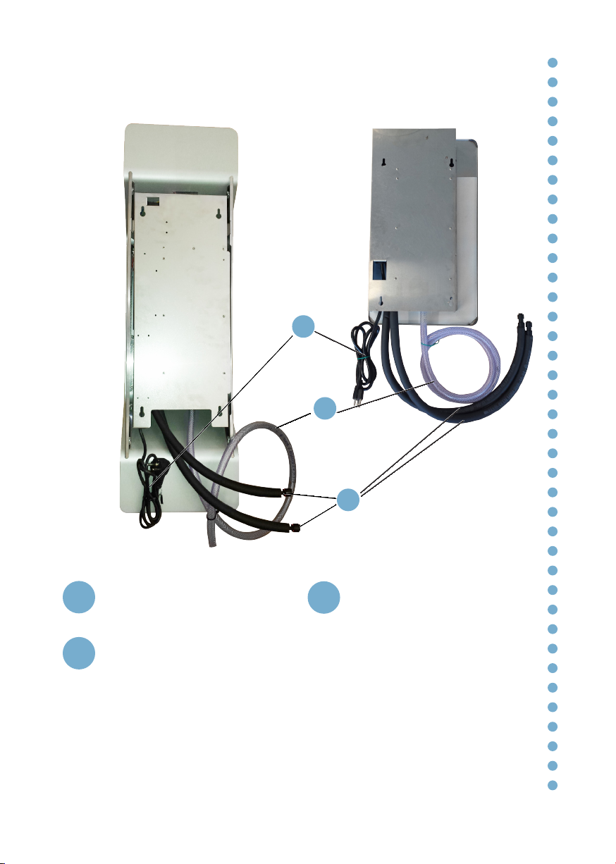
Rear view
Cold water and sparkling water
inlet pipes Ø8mm
1Power cable
3
Drip tray waste pipe Ø17mm
2
1
2
3

12
Description of the keyboard
P. 1 P. 2
P. 1 Sparkling water dispensing button
P. 2 Cold water dispensing button
The water is dispensed while pressure is being applied to the button.
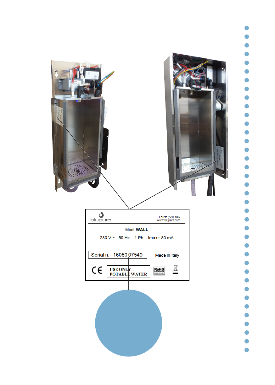
13
Technical Features – Technical Data Plate
16 Year of manufacture
06 Month of manufacture
07549 Serial number

14
Technical Features - dimensions (mm)
[mod. WALL]
[mod. WALL built-in]
131
295
544,6
306,4
E
E
455
36,4
110,1
17,2
103,1
491
110,1
12,5
70,1
7
224,6
10,5
31,1
307,7
110,1

15
Technical data sheet WALL WALL
built-in
Power supply 230 V - 50 Hz
Power consumption 18,4W
Inlet water pipes Ø 8 x 1 mm
Dimensions LxDxH (mm) 273 x 114 x 900 306 x 110 x 545
Packaging dimensions LxDxH (mm) 320 x 170 x 950 -
Net weight (kg) 7
Gross weight (kg) 8
16
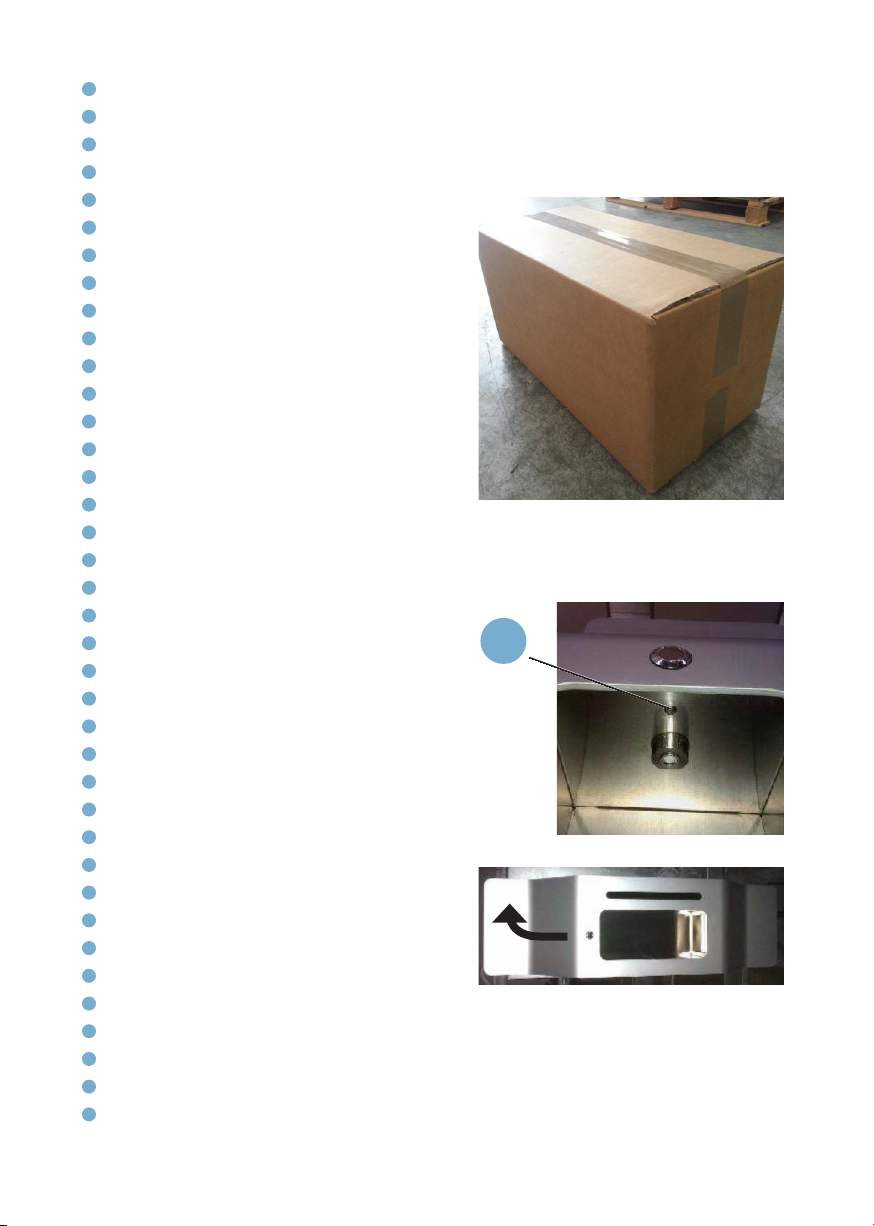
Installation
Unpacking
Remove the two plastic tape and the
internal packing.
Carefully check that the unit has not
been damaged during transport. Any
signs of damage must be reported to the
forwarder immediately.
Ensure that a qualified technician
connects it to the electric supply following
the manufacturer’s instructions and
according to the local safety regulations.
The end user is not permitted to access
the internal service parts of the unit. Only
technical personnel should carry out
operations of this nature.
Siting the unit
Wear safety gloves when handling the
unit. Take care when touching the metal
parts, which could be sharp.
Site the unit away from sources of heat
and on a flat and strong surface suitable
to support its weight.
Unscrew the cross head screw placed on
the top surface of the supply zone, near
the nozzle (1).
Separate the aluminium cover and the
sides from the rear frame, pushing up and
pulling towards yourself (fig. 16.3).
Unplug the electrical connector (2, fig.
17.1).
Using some screws, fix the unit on the 4
Ø6 holes on the back.
Use the provided washers to separate
the frame from the wall and appropriate
screws and anchors according the type of
wall.
Fig. 16.\
Fig. 16.2
Fig. 16.3
1
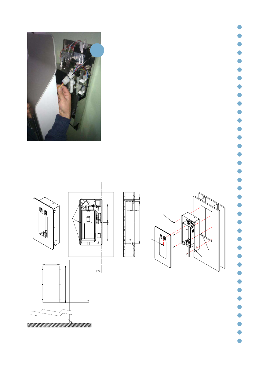
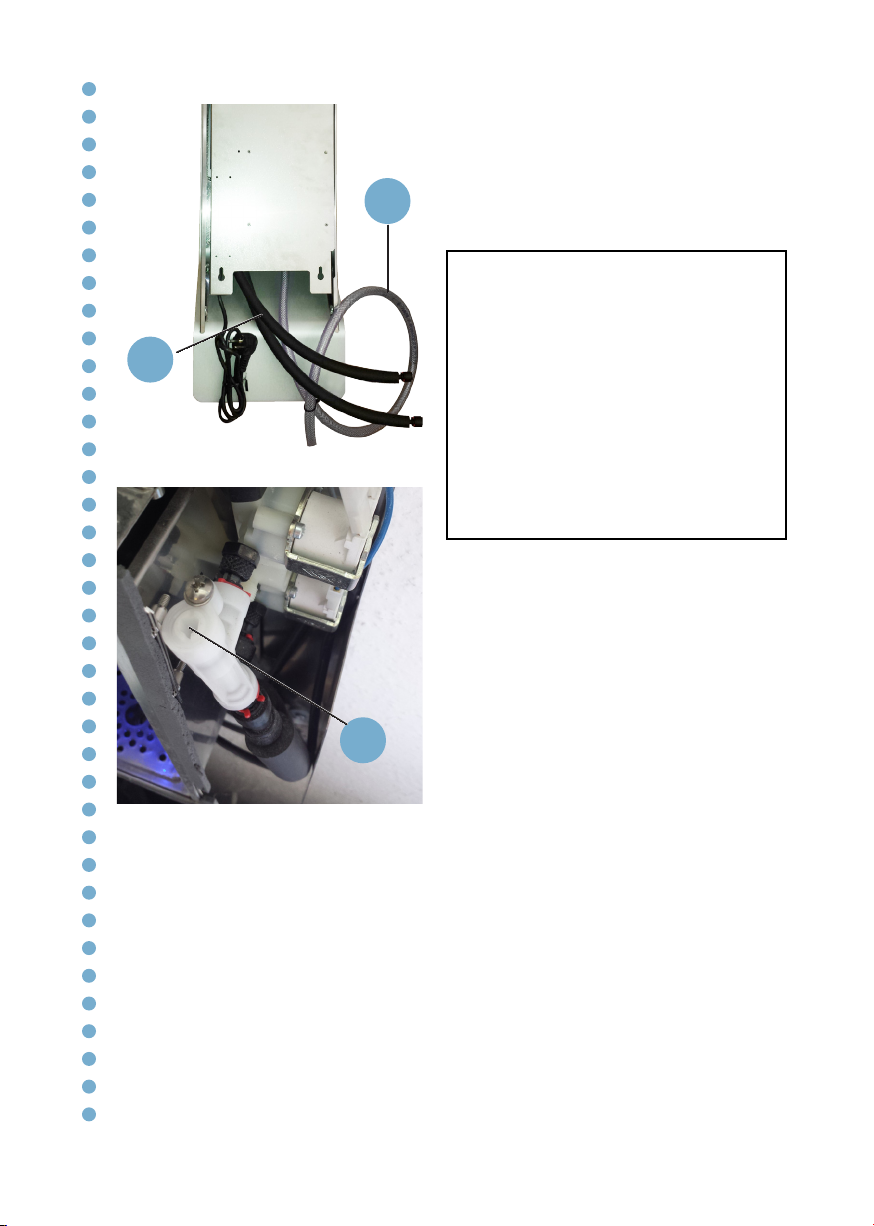
17
Once the frame is fixed to the wall,
connect the supply cable, the water
pipe and insert the wastewater pipe in
the predisposed conduit.
For the built-in version, prepare the
housing in the wall (dim. LxDxH:
225x110x491) and fix the unit in
place with nuts and washers using the
appropriate holes on the front or the
side (fig. 17.2).
Reconnect the contacts indicated
above and relocate the frontal cover
making it slide downwards on the rear
frame. Tighten the safe screw on the
supply zone.
3
5
4
4
recommended
height
935
226
495
FLOOR
200
200
237,1
F
F
3
23,5
21455
SECTION F-F
SCALE 1 : 8
4
4
Sizes
range
housing
machine
1 - Create hole on plasterboard panel
2 - Prepare water supply (pipe ø8), drainage (pipe 17ø) and
electricity (230V 50Hz)
3 - Fix the machine on the plasterboard panel with 6 screws on
the front of machine
4 - If you can fix the machine laterally on the side upright or
plasterboard panel
5 - Fix the front panel with the safety screw in the bottle compartment
Fig. 17.2
Fig. 17.1
2
18
Connection to the water cooler
This unit must be connected to an under-
sink cooler. Refer to the relevant manual
for the purchased model. Do not connect
this unit directly to the mains water
supply.
Connect the incoming water pipes of the
unit (1, ext. diameter 8 mm) to the water
cooler. Connect the waste pipe (2) to a
waste water manifold.
Make sure that the connecting pipes
between the cooler and the Wall
are adequately insulated to prevent
condensation.
On the “Fizz” models with sparkling
water, you can adjust the output stream
with the screw on the compensator (3).
Turn the screw clockwise to decrease the
flow or counterclockwise to increase it.
Once the pipes are attached, turn on the
tap. Ensure there are no leaks.
Attention!
To connect the water cooler to the mains
water supply, you will need to use a new
set of connectors (joints, gaskets and
pipes).
Do not use a set of connectors that has
already been used elsewhere.
The water pressure entering the unit must
be between a minimum of 1,0 bar (0.10
MPa) and a maximum of 3,5 bar (0.35
MPa).
Fig. 18.1
1
2
Fig. 18.2
3
19
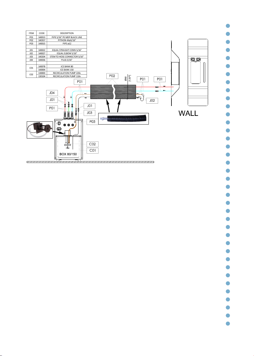
Fig. 19.1 - Example of typical installation
*
*Optional on models Box 80/150

20
Electrical connection
The connections must comply with
local regulations. The grounding of the
unit is a legal requirement.
Connect the power cable (1) to a
socket. The electronic tap is now
activated and the keypad is turned on.
Press the “Sparkling Water” button (P.1)
in order to release any air in the circuit
and to allow the pump on the under
counter water cooler to start and fill
the carbonator with water.
Fig. 20.1
1
P. 1
Fig. 20.2
This manual suits for next models
1
Table of contents
Popular Dispenser manuals by other brands


ViscoTec
ViscoTec Preeflow eco-PEN300 Operation & maintenance manual

egepack
egepack eone 45570 instruction manual

Piusi
Piusi SUZZARABLUE PRO Installation, use and maintenance manual

SILADENT
SILADENT DA 2000 Working Instruction

Curtis
Curtis Primo Cappuccino PCGT5DV user guide

Beper
Beper P201UTP004 use instructions