BMW F48 Installation guide

Technical�training.
Product�information.
BMW�Service
F48�General�Vehicle�Electronics

General�information
Symbols�used
The�following�symbol�is�used�in�this�document�to�facilitate�better�comprehension�or�to�draw�attention
to�very�important�information:
Contains�important�safety�information�and�information�that�needs�to�be�observed�strictly�in�order�to
guarantee�the�smooth�operation�of�the�system.
Information�status�and�national-market�versions
BMW�Group�vehicles�meet�the�requirements�of�the�highest�safety�and�quality�standards.�Changes
in�requirements�for�environmental�protection,�customer�benefits�and�design�render�necessary
continuous�development�of�systems�and�components.�Consequently,�there�may�be�discrepancies
between�the�contents�of�this�document�and�the�vehicles�available�in�the�training�course.
This�document�basically�relates�to�the�European�version�of�left-hand�drive�vehicles.�Some�operating
elements�or�components�are�arranged�differently�in�right-hand�drive�vehicles�than�shown�in�the
graphics�in�this�document.�Further�differences�may�arise�as�a�result�of�the�equipment�specification�in
specific�markets�or�countries.
Additional�sources�of�information
Further�information�on�the�individual�topics�can�be�found�in�the�following:
• Owner's�Handbook
• Integrated�Service�Technical�Application.
Contact:�conceptinfo@bmw.de
©2015�BMW�AG,�Munich
Reprints�of�this�publication�or�its�parts�require�the�written�approval�of�BMW�AG,�Munich
The�information�contained�in�this�document�forms�an�integral�part�of�the�technical�training�of�the
BMW�Group�and�is�intended�for�the�trainer�and�participants�in�the�seminar.�Refer�to�the�latest�relevant
information�systems�of�the�BMW�Group�for�any�changes/additions�to�the�technical�data.
Information�status:�June�2015
BV-72/Technical�Training

F48�General�Vehicle�Electronics
Contents
1. Vehicle�Electrical�System............................................................................................................................................................................................. 1
1.1. Data�bus�overview................................................................................................................................................................................................ 1
1.2. Main�bus�systems.................................................................................................................................................................................................3
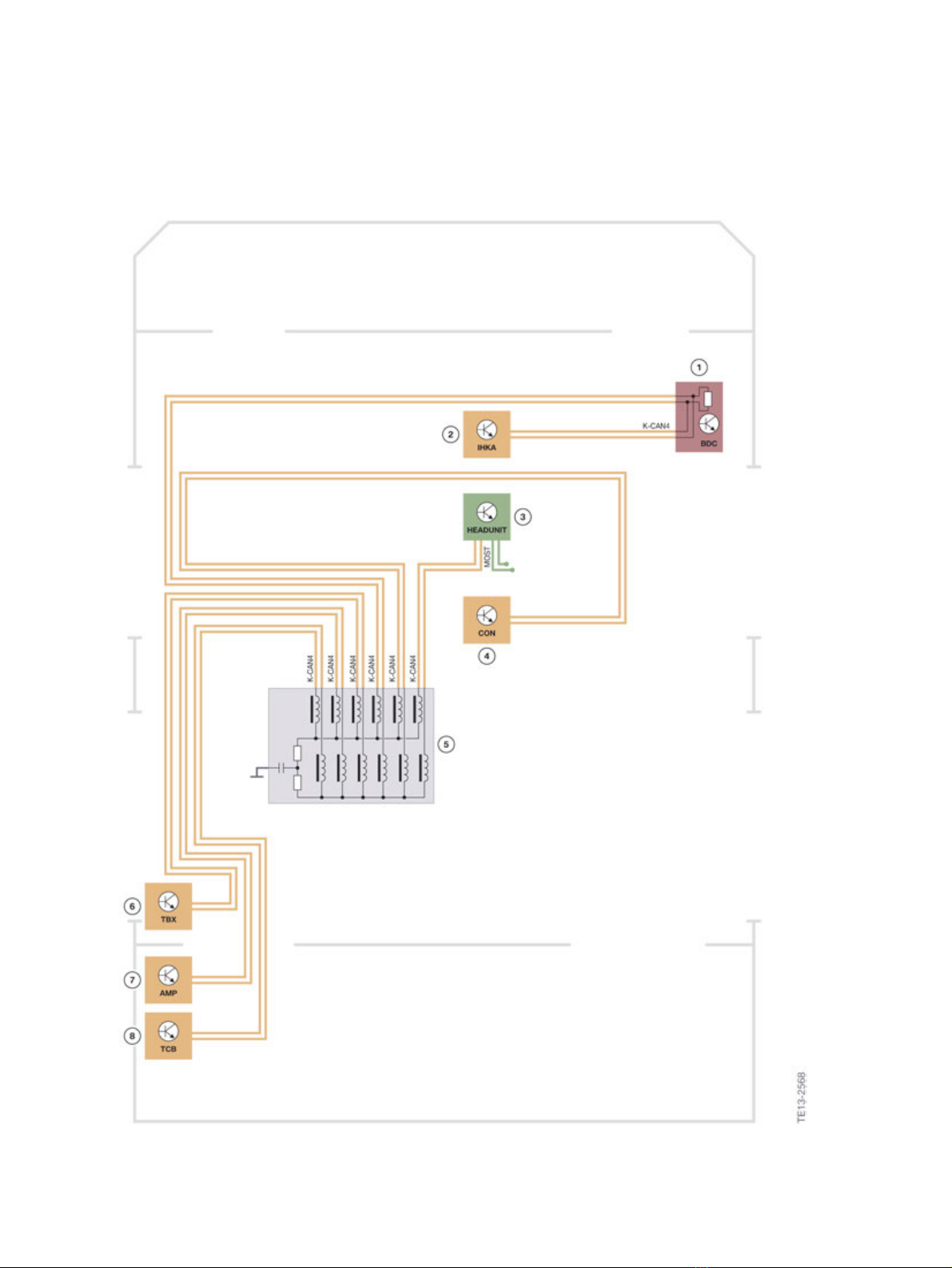
1.2.1. K-CAN.................................................................................................................................................................................................... 3
1.2.2. PT-CAN................................................................................................................................................................................................ 8
1.2.3. FlexRay..................................................................................................................................................................................................9
1.2.4. D-CAN................................................................................................................................................................................................13
1.2.5. Ethernet...........................................................................................................................................................................................13
1.2.6. MOST..................................................................................................................................................................................................13
1.3. Sub-bus�systems...............................................................................................................................................................................................13
1.3.1. Local�interconnect�network�bus...............................................................................................................13
1.3.2. Local-CAN...................................................................................................................................................................................14
1.3.3. USB........................................................................................................................................................................................................ 14
1.3.4. APIX....................................................................................................................................................................................................... 14
1.4. Control�units.............................................................................................................................................................................................................. 15
1.4.1. Complete�overview........................................................................................................................................................15
1.4.2. Body�Domain�Controller....................................................................................................................................... 17
1.4.3. Frontal�Light�Electronics...................................................................................................................................... 17
1.4.4. TRSVC�control�unit.......................................................................................................................................................18
1.4.5. Park�Distance�Control/Parking�Maneuver�Assistant................................................. 19
1.4.6. Crash�Safety�Module................................................................................................................................................. 20
1.4.7. Dynamic�Stability�Control...................................................................................................................................20
1.4.8. Optional�equipment�system............................................................................................................................21
1.4.9. Camera-based�driver�support�systems.........................................................................................22
1.4.10. Automatic�operation�of�tailgate................................................................................................................. 23
1.4.11. Longitudinal�torque�distribution............................................................................................................... 23
2. Voltage�Supply............................................................................................................................................................................................................................. 24
2.1. Overview.......................................................................................................................................................................................................................... 24
2.2. Components.............................................................................................................................................................................................................. 26
2.2.1. Battery............................................................................................................................................................................................... 27
2.2.2. Intelligent�battery�sensor.....................................................................................................................................27
2.2.3. Power�distribution�boxes......................................................................................................................................28
3. Exterior�Lights............................................................................................................................................................................................................................... 30
3.1. Headlights......................................................................................................................................................................................................................30
3.1.1. Halogen�headlight........................................................................................................................................................... 30
3.1.2. LED�headlight�with�extended�scope..................................................................................................31
3.1.3. fog�lights........................................................................................................................................................................................ 34
3.2. Rear�lights..................................................................................................................................................................................................................... 35
3.2.1. In�vehicles�with�halogen�headlights....................................................................................................35

F48�General�Vehicle�Electronics
Contents
3.2.2. Vehicles�with�LED�headlights.......................................................................................................................36
4. Interior�Lighting.......................................................................................................................................................................................................................... 37
4.1. System�wiring�diagram............................................................................................................................................................................. 38
5. Heating/Air�Conditioning�Systems..........................................................................................................................................................41
5.1. Components�and�systems..................................................................................................................................................................41
5.1.1. Integrated�automatic�heating�and�air�conditioning......................................................41
5.1.2. Heating�and�air-conditioning�unit...........................................................................................................46
5.1.3. Microfilter...................................................................................................................................................................................... 48
5.1.4. Air/Water�separation�(Venturi�adapter)........................................................................................... 49
5.1.5. ECO�PRO�mode�of�heating�and�air�conditioning�program...............................51
6. Locking�and�Security�Functions..................................................................................................................................................................52
6.1. Overview�of�functions.................................................................................................................................................................................54
6.1.1. Remote�control�receiver........................................................................................................................................ 55
6.2. Central�locking�system............................................................................................................................................................................. 55
6.2.1. Special�functions.............................................................................................................................................................. 56
6.2.2. System�wiring�diagram............................................................................................................................................57
6.3. Comfort�Access................................................................................................................................................................................................... 59
6.3.1. System�wiring�diagram............................................................................................................................................60
6.3.2. System�components...................................................................................................................................................62
6.4. Hands�free�tailgate�opening............................................................................................................................................................. 63
6.4.1. System�wiring�diagram............................................................................................................................................64
6.4.2. Functional�description�of�tailgate�opening.............................................................................. 65
7. Alarm�System..................................................................................................................................................................................................................................69
7.1. System�wiring�diagram............................................................................................................................................................................. 69
8. Wash/Wipe�System...............................................................................................................................................................................................................71
8.1. Introduction................................................................................................................................................................................................................. 71
8.2. Operation........................................................................................................................................................................................................................ 71
8.3. System�wiring�diagram............................................................................................................................................................................. 72
9. Steering�Wheel�Heating...............................................................................................................................................................................................74
9.1. System�wiring�diagram............................................................................................................................................................................. 74

F48�General�Vehicle�Electronics
1.�Vehicle�Electrical�System
1
1.1.�Data�bus�overview
F48�data�bus�overview

F48�General�Vehicle�Electronics
1.�Vehicle�Electrical�System
2
Index Explanation
1 Start-up�node�control�units�for�starting�and
synchronizing�the�FlexRay�bus�system
2 Control�units�with�wake-up�authorisation
ACSM Advanced�Crash�Safety�Module
AMP Audio�amplifier
BDC Body�Domain�Controller
CID Central�information�display
CON Controller
DME Digital�Motor�Electronics
DSC Dynamic�Stability�Control
EGS Electronic�transmission�control
EPS Electronic�Power�Steering
FLEL Frontal�Light�Electronics�Left
FLER Frontal�Light�Electronics�Right
FZD Roof�function�center
HEADUNIT Headunit
HKL Automatic�operation�of�tailgate
HUD Head‐Up�Display
IHKA Integrated�heating�and�air�conditioning
KAFAS Camera-based�driver�support�systems
KOMBI Instrument�cluster
LMV Longitudinal�torque�distribution
PDC Park�Distance�Control
PMA Parking�Manoeuvring�Assistant
SAS Optional�equipment�system
SMFA Driver's�seat�module
TBX Touchbox
TCB Telematic�Communication�Box
TRSVC Control�unit�for�rear�view�camera�and�Side�View
ZGM Central�gateway�module

F48�General�Vehicle�Electronics
1.�Vehicle�Electrical�System
3
1.2.�Main�bus�systems
1.2.1.�K-CAN
In�the�F48�the�following�K-CANs�are�used:
• K-CAN2
• K-CAN3
• K-CAN4
All�K-CAN�data�buses�have�a�data�transfer�rate�of�500kBit/s.
The�K-CAN�with�100�kBit/s�is�no�longer�used�in�the�F48.

F48�General�Vehicle�Electronics
1.�Vehicle�Electrical�System
4
K-Can�termination
F48�K-Can�termination

F48�General�Vehicle�Electronics
1.�Vehicle�Electrical�System
5
Index Explanation
1 Body�Domain�Controller�(BDC)
2 Integrated�heating�and�air�conditioning
3 Headunit
4 Controller�(CON)
5 K-CAN�terminator
6 Touchbox�(TBX)
7 Audio�amplifier�(AMP)
8 Telematic�Communication�Box�(TCB)
The�CAN�buses�are�shown�in�the�overview�of�the�bus�systems.�The�actual�physical�layout�(topology)�is
shown�using�the�example�of�the�K-CAN2.
As�with�most�bus�systems,�terminating�resistors�are�also�used�for�protection�of�the�K-CAN�to�avoid
residual�voltages�on�the�data�lines.
The�terminating�resistors�for�the�termination�are�located�in�the:
• Body�Domain�Controller�and
• K-CAN�terminators.
All�other�control�units�are�connected�at�the�K-CAN�terminator�without�a�terminating�resistor.

F48�General�Vehicle�Electronics
1.�Vehicle�Electrical�System
6
CAN�terminator
CAN�terminator
Depending�on�the�equipment�package,�in�the�CAN�terminator�the�terminating�resistor�for�the
corresponding�CAN�bus�is�installed.�The�terminating�resistor�comprises�two�resistances�connected
in�series,�each�60�Ohm.�A�measuring�tap�against�ground�with�a�capacitor�for�the�reduction�of�high-
frequency�faults�is�also�installed.�Ferrite�beads�are�installed�for�all�bus�lines�in�the�CAN�terminator.
Ferrite�beads�suppress�high-frequency�faults�on�the�CAN�data�lines,�thus�making�possible�line�lengths
of�up�to�5m�in�the�wiring�harness.
Ferrite�core
A�ferrite�core�is�a�component�made�from�the�ferromagnetic�material�iron�oxide�hematite�(Fe203).�It�is
characterized�by�low�or�no�conductivity.�The�inductance�or�the�magnetic�field�is�increased�as�part�of�a
coil�(throttle�or�transformer).�If�a�ferrite�core�is�secured�around�a�conductor,�which�routes�signals�at�low
frequency�or�direct�current�voltage,�high-frequency�faults�are�attenuated�with�its�help.
Ferrite�core
Index Explanation
1 Ferrite�core�using�the�example�of�a�USB�line

F48�General�Vehicle�Electronics
1.�Vehicle�Electrical�System
7
Oscilloscope
If�there�are�no�terminating�resistors�in�a�CAN�bus�or�they�are�faulty,�this�may�lead�to�reflections�or
faults.�These�reflections�or�faults�are�shown�in�the�following�graphic:
Oscilloscope�holder�K-CAN
Index Explanation
1 Oscilloscope�holder�with�active�CAN�terminator
2 Oscilloscope�holder�with�disconnected�or�faulty�CAN�terminator

F48�General�Vehicle�Electronics
1.�Vehicle�Electrical�System
8
Installation�location
Depending�on�the�equipment�package,�a�maximum�of�four�CAN�terminators�are�installed�in�the�F48.
The�installation�locations�are�shown�in�the�following�graphic:
F48�installation�location�of�CAN�terminators
Index Explanation
1 CAN�terminator�integrated�in�the�Body�Domain�Controller
2 K-CAN3�terminator,�rear�right
3 K-CAN2�terminator,�rear�right
4 K-CAN4�terminator,�rear�left
1.2.2.�PT-CAN
In�the�F48�the�following�PT-CANs�are�used:
• PT-CAN
• PT-CAN2

F48�General�Vehicle�Electronics
1.�Vehicle�Electrical�System
9
1.2.3.�FlexRay
F48�system�wiring�diagram�for�FlexRay

F48�General�Vehicle�Electronics
1.�Vehicle�Electrical�System
10
Index Explanation
1 Digital�Motor�Electronics�(DME)
2 Electronic�Power�Steering�(electromechanical�power�steering)�(EPS)
3 Dynamic�Stability�Control�(DSC)
4 Body�Domain�Controller�(BDC)
5 Optional�equipment�system�(SAS)
6 Crash�Safety�Module�(ACSM)
FlexRay�data�bus�topology
The�FlexRay�is�shown�in�a�simplified�form�in�the�data�bus�overview.�The�actual�topology�(star-shaped
data�bus�topology)�is�shown�in�the�graphic�at�the�top.
The�star�coupler�with�four�drivers�is�located�in�the�Body�Domain�Controller�(BDC).�The�FlexRay�control
units�are�connected�to�these�bus�drivers�independent�of�their�termination�type.
Bus�termination
As�with�most�bus�systems,�resistors�are�also�used�for�termination�for�the�FlexRay�to�avoid�reflections
on�the�data�lines�at�both�ends�of�the�data�lines.�The�value�of�these�terminating�resistors�is�calculated
from�the�data�transfer�speed�and�the�cable�lengths.�The�terminating�resistors�are�located�in�the�control
units.�In�the�F48�the�terminating�resistors�have�a�value�of�90ohm�(total�resistance�45ohm).
Use�the�vehicle�wiring�diagram�for�measuring�the�(de-energized)�FlexRay�data�bus�for�the
determination�of�the�line�or�terminating�resistor.
Signal�properties
Electrical�faults,�which�arise�from�incorrect�cable�routing,�contact�resistances,�etc.�may�cause�faulty
data�transfer.

F48�General�Vehicle�Electronics
1.�Vehicle�Electrical�System
11
Oscilloscope�presentation�of�FlexRay
The�voltage�ranges�of�the�FlexRay�bus�system�are:
• System�ON�-�no�bus�communication�2.5V
• High�signal�-�3.1V�(voltage�signal�increases�to�600mV�and�upwards)
• Low�signal�-�1.9V�(voltage�signal�decreases�from�600mV�downwards)
The�voltage�values�are�measured�against�ground.

F48�General�Vehicle�Electronics
1.�Vehicle�Electrical�System
12
Deterministic�data�transfer
Index Explanation
1 Time-controlled�range�of�cyclical�data�transfer
2 Event-controlled�range�of�cyclical�data�transfer
3 Cycle�[5ms�overall�cycle�duration,�of�which�3ms�static�(=�time-controlled)
and�2ms�dynamic�(=�event-controlled)]
n Speed�of�rotation
<° Angle
t° Temperature
v Speed
xyz...�abc... Event-controlled�information
t Time

F48�General�Vehicle�Electronics
1.�Vehicle�Electrical�System
13
The�CAN�bus�system�is�an�event-controlled�bus�system.�Data�is�transmitted�when�an�event�occurs.
As�these�events�have�different�priorities�(e.g.�ambient�temperature�has�a�lower�priority�than�a�DSC
intervention,�for�example),�the�priorities�are�also�sent�in�the�bus�message.�The�message�with�the
higher�priority�is�sent�first.�As�the�control�unit�still�wants�to�send�the�message�which�has�the�lower
priority,�it�frequently�results�in�overloading�in�the�bus�systems.
The�FlexRay�works�with�so-called�"time�slots".�With�this�method�the�messages�are�sent�and�are�not
controlled�by�events,�but�each�control�unit�in�the�FlexRay�network�is�assigned�a�fixed�time�slot�in�which
it�sends�its�message�within�a�certain�period.�This�time�slot�is�synchronised�with�every�restart�of�the
data�bus.�The�control�units�which�synchronize�the�FlexRay�are�always�labelled�in�the�bus�diagram�with
a�"S"�(see�chapter�1.1).
The�FlexRay�can�also�be�synchronised�with�the�BMW�diagnosis�system�in�the�event�of�a�fault�and
corresponding�fault�code.
1.2.4.�D-CAN
The�D-CAN�for�the�vehicle�diagnosis�has�a�data�transfer�rate�of�500�kBit/s.
1.2.5.�Ethernet
The�Ethernet�access�is�used�for�programming�the�entire�vehicle.
In�a�F48�with�navigation�system�the�map�update�for�the�navigation�can�also�be�effected�using�the
Ethernet�interface.
1.2.6.�MOST
In�the�F48�the�Media�Oriented�System�Transport�(MOST)�bus�works�at�a�data�transfer�rate�of
22.5MBit/s.
1.3.�Sub-bus�systems
1.3.1.�Local�interconnect�network�bus
Different�data�rates�are�used�for�the�local�interconnect�network�bus�according�to�the�information
required.�The�data�transfer�rates�of�the�local�interconnect�network�bus�in�the�F48�range�from�19.2kBit/
s�to�20.0kBit/s.
Examples:
• 19.2�kBit/s�FLEL,�FLER
• 20.0�kBit/s�remote�control�receiver
The�Body�Domain�Controller�is�designed�for�the�different�data�rates�at�the�corresponding�inputs.

F48�General�Vehicle�Electronics
1.�Vehicle�Electrical�System
14
1.3.2.�Local-CAN
With�corresponding�optional�equipment,�the�Local�Controller�Area�Network�connects�the�optional
equipment�system�(SAS)�with�the�control�unit�for�the�camera-based�driver�support�systems�(KAFAS).
The�Local�Controller�Area�Network�has�a�data�transfer�rate�of�500kBit/s.
1.3.3.�USB
Depending�on�the�equipment,�the�following�USB�connections�are�possible:
• from�the�headunit�to�the�Telematic�Communication�Box�(TCB)
• from�the�headunit�to�the�telephone�base�plate
• from�the�headunit�to�the�USB�port
1.3.4.�APIX
The�central�information�display�(CID)�and�the�Head‐Up�Display�(HUD)�in�the�F48�are�not�connected�to
a�vehicle�data�bus.�Both�control�units�are�connected�directly�to�the�headunit�via�an�APIX�interface�or
the�instrument�cluster�(KOMBI).�APIX�(Automotive�Pixel�Link)�is�a�bit-serial�data�transfer�system.
APIX
Index Explanation
1 APIX�transmitter
2 Message�to�be�sent�(max.�1Gbit/s)
3 APIX�receiver
4 Confirmation�message�(62.5Mbit/s)

F48�General�Vehicle�Electronics
1.�Vehicle�Electrical�System
15
1.4.�Control�units
This�chapter�contains�information�on�control�units,
• which�are�used�for�the�first�time�in�the�F48
• which�have�been�adapted�for�the�F48
1.4.1.�Complete�overview
The�installation�locations�of�all�the�control�units�are�shown�in�the�following�graphic.
F48�Installation�location�of�the�control�units

F48�General�Vehicle�Electronics
1.�Vehicle�Electrical�System
16
Index Explanation
1 Frontal�Light�Electronics�Right�(FLER)
2 Dynamic�Stability�Control�(DSC)
3 Body�Domain�Controller�(BDC)
4 Camera-based�driver�support�systems�(KAFAS)
5 Headunit
6 Controller�(CON)
7 Roof�function�center�(FZD)
8 Optional�equipment�system�(SAS)
9 Park�Distance�Control�(PDC)/Parking�Manoeuvring�Assistant�(PMA)
10 Automatic�operation�of�tailgate�(HKL)
11 Rear�view�camera�(RFK)
12 Telematic�Communication�Box�(TCB)
13 Amplifier�(AMP)
14 Touchbox�(TBX)
15 Longitudinal�torque�distribution�(LMV)
16 Crash�Safety�Module�(ACSM)
17 Driver's�seat�module(SMFA)
18 Instrument�cluster�(KOMBI)
19 Integrated�heating�and�air�conditioning�(IHKA)
20 Electronic�Power�Steering�(EPS)
21 Digital�Engine�Electronics�(DME)
22 Electronic�transmission�control�(EGS)
23 Frontal�Light�Electronics�Left�(FLEL)
Other manuals for F48
2
Table of contents
Other BMW Automobile manuals

BMW
BMW Z4 2005 User manual

BMW
BMW 2007 5 Series User manual

BMW
BMW 5 SERIES - CATALOGUE User manual

BMW
BMW M5 User manual

BMW
BMW 528e Programming manual

BMW
BMW 3 SERIES SEDAN - PRODUCT CATALOGUE User manual

BMW
BMW F34 LCI 2016 User manual

BMW
BMW M3 BROCHURE 2010 User manual

BMW
BMW 745i User manual

BMW
BMW 635CSi 1989 Programming manual

BMW
BMW F11 Manual

BMW
BMW 5 series sedan User manual

BMW
BMW 3 SERIES CONVERTIBLE - CATALOGUE User manual

BMW
BMW 328i xDrive User manual

BMW
BMW M COUPE 2002 User manual

BMW
BMW Z8 2000 User manual

BMW
BMW M3 CONVERTIBLE 2001 User manual

BMW
BMW M3 CONVERTIBLE 2005 User manual

BMW
BMW 4 series User manual

BMW
BMW 735i Programming manual