BMW G15 Installation guide

Technical�training.
Product�information.
BMW�Service
G15�Displays�and�Controls

General�information
Symbols�used
The�following�symbol�is�used�in�this�document�to�facilitate�better�comprehension�or�to�draw�attention
to�very�important�information:
Contains�important�safety�information�and�information�that�needs�to�be�observed�strictly�in�order�to
guarantee�the�smooth�operation�of�the�system.
Information�status:�June�2018
BMW�Group�vehicles�meet�the�requirements�of�the�highest�safety�and�quality�standards.�Changes
in�requirements�for�environmental�protection,�customer�benefits�and�design�render�necessary
continuous�development�of�systems�and�components.�Consequently,�there�may�be�discrepancies
between�the�contents�of�this�document�and�the�vehicles�available�in�the�training�course.
The�information�contained�in�the�training�course�materials�is�solely�intended�for�participants�in�this
training�course�conducted�by�BMW�Group�Technical�Training�Centers,�or�BMW�Group�Contract
Training�Facilities.
This�training�manual�or�any�attached�publication�is�not�intended�to�be�a�complete�and�all�inclusive
source�for�repair�and�maintenance�data.�It�is�only�part�of�a�training�information�system�designed�to
assure�that�uniform�procedures�and�information�are�presented�to�all�participants.
For�changes/additions�to�the�technical�data,�repair�procedures,�please�refer�to�the�current�information
issued�by�BMW�of�North�America,�LLC,�Technical�Service�Department.
This�information�is�available�by�accessing�TIS�at�www.bmwcenternet.com.
Additional�sources�of�information
Further�information�on�the�individual�topics�can�be�found�in�the�following:
• Owner's�Handbook
• Integrated�Service�Technical�Application
• Aftersales�Information�Research�(AIR)
The�information�contained�in�this�manual�is�not�to�be�resold,�bartered,�copied,�or�transferred
without�the�express�written�consent�of�BMW�of�North�America,�LLC�(“BMW�NA”).
©2018�BMW�of�North�America,�LLC
The�BMW�name�and�logo�are�registered�trademarks.�All�rights�reserved.

G15�Displays�and�Controls
Contents
1. Operating�Elements................................................................................................................................................................................................................. 1
1.1. Introduction..................................................................................................................................................................................................................... 1
1.1.1. New�features�in�the�G15.......................................................................................................................................... 1
1.1.2. Overview�of�the�interior.............................................................................................................................................. 2
1.1.3. Overview�of�displays....................................................................................................................................................... 3
1.1.4. Audio�operating�unit........................................................................................................................................................ 4
1.1.5. Heating�and�air-conditioning�controls................................................................................................. 4
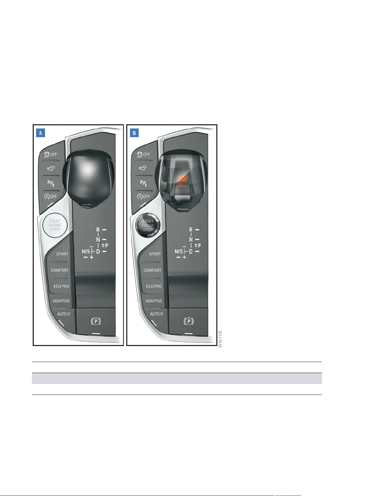
1.2. Center�console�switch�cluster...........................................................................................................................................................4
1.2.1. Variants................................................................................................................................................................................................. 6
1.3. Light�operating�unit............................................................................................................................................................................................ 7
1.4. Doors......................................................................................................................................................................................................................................... 8
1.5. 2/2-zone�air�conditioning�control�panel............................................................................................................................. 9
2. Instrument�Cluster.................................................................................................................................................................................................................11
2.1. Introduction................................................................................................................................................................................................................. 11
2.2. Connection...................................................................................................................................................................................................................11
3. Controller.................................................................................................................................................................................................................................................13
3.1. Overview.......................................................................................................................................................................................................................... 13
3.2. Installation�location......................................................................................................................................................................................... 14
4. Central�Information�Display................................................................................................................................................................................. 15
4.1. ID7..............................................................................................................................................................................................................................................15
5. Gesture�Control...........................................................................................................................................................................................................................17
5.1. Introduction................................................................................................................................................................................................................. 17
5.2. Installation�location......................................................................................................................................................................................... 18
5.3. System�wiring�diagram............................................................................................................................................................................. 19
6. Head‐Up�Display....................................................................................................................................................................................................................... 20
6.1. Introduction................................................................................................................................................................................................................. 20
6.2. System�wiring�diagram............................................................................................................................................................................. 20
7. Multifunction�Steering�Wheel...........................................................................................................................................................................21
7.1. Control�panels�...................................................................................................................................................................................................... 21
7.1.1. Assistance�systems..................................................................................................................................................... 21
7.1.2. Multimedia...................................................................................................................................................................................22
7.1.3. Steering�wheel�heating...........................................................................................................................................23


G15�Displays�and�Controls
1.�Operating�Elements
1
1.1.�Introduction
1.1.1.�New�features�in�the�G15
The�following�table�shows�the�new�features�of�and�changes�to�the�display�and�operating�elements�in
the�G15:
Function New�feature/change
Controllers Controller�with�8�direct�access�keys
Central�Information�Display 12.3”�Central�Information�Display�with�a
Head�Unit�High�3
User�interface User�interface�ID7
Light�operating�unit Rotary�controller�has�been�replaced�by�push
buttons

G15�Displays�and�Controls
1.�Operating�Elements
2
1.1.2.�Overview�of�the�interior
The�interior�and�the�operating�area�(cockpit)�of�the�G15�have�been�newly�designed.�Among�the�new
features�is�the�new�layout�of�the�air�conditioning�control�and�the�audio�operating�unit.
The�following�graphic�shows�the�display�and�operating�elements�of�the�G15:
G15�Overview�of�the�interior
Index Explanation
1 Instrument�cluster
2 Head‐Up�Display
3 Central�Information�Display
4 Air�conditioning�control�panel
5 Audio�operating�unit
6 Gear�selector�switch
7 Controllers
8 Center�console�control�panel
9 Multifunction�steering�wheel

3
G15�Displays�and�Controls
1.�Operating�Elements
1.1.3.�Overview�of�displays
G15�overview�of�displays
Index Explanation
1 Head‐Up�Display�(HUD)
2 Central�Information�Display�(CID)
3 Instrument�cluster�(KOMBI)

G15�Displays�and�Controls
1.�Operating�Elements
4
1.1.4.�Audio�operating�unit
G15�audio�operating�unit
Index Explanation
1 Select�AM,�FM
2 Change�entertainment�source
3 Press:�Switch�sound�output�on/off;�turn:�Set�volume
4 Favorite�buttons
5 Press�once:�Change�station/track;�press�and�hold:�fast�forward/rewind�track
1.1.5.�Heating�and�air-conditioning�controls
G15�Heating�and�air�conditioning�controls
1.2.�Center�console�switch�cluster
The�following�graphic�shows�the�operating�elements�in�the�Center�console:

G15�Displays�and�Controls
1.�Operating�Elements
5
G15�Center�Operation�Unit
Index Explanation
1 Gear�selector�switch
2 Controller
3 Electromechanical�parking�brake
4 Automatic�Hold
5 Driving�experience�switch
6 Start/Stop�button
7 Activate/deactivate�engine�start/stop
8 Parking�Manoeuvring�Assistant
9 Surround�view�camera
10 Dynamic�Stability�Control

6
G15�Displays�and�Controls
1.�Operating�Elements
1.2.1.�Variants
The�center�console�switch�cluster�consists�of�two�different�equipment�specifications:
• Standard
• Glass�controls�(SA�4A2)
Center�console�switch�cluster�variants
Index Explanation
A Center�console�switch�cluster�with�the�standard�equipment
B Center�console�switch�cluster�with�the�optional�glass�controls�(SA�4A2)

G15�Displays�and�Controls
1.�Operating�Elements
7
1.3.�Light�operating�unit
A�new�light�operating�unit�is�used�for�the�first�time�in�the�G15.�The�light�switch�element�is�situated�next
to�the�steering�wheel.�With�the�optional�equipment�Night�Vision�with�Pedestrian�Detection�(SA�6UK)
the�light�operating�unit�is�additionally�equipped�with�a�Night�Vision�button.
The�following�graphic�shows�a�light�operating�unit�that�features�the�maximum�equipment�specification.
G15�light�operating�unit
Index Explanation
a Light�switch
1 Lights�off;�daytime�driving�lights
2 Automatic�driving�lights�control;�adaptive�lighting�functions
3 Low-beam�headlight
4 Night�Vision�(SA�6UK)
5 Instrument�lighting
6 Right�parking�light
7 Side�lights
8 Left�parking�light

G15�Displays�and�Controls
1.�Operating�Elements
8
1.4.�Doors
Here�you�can�see�an�overview�of�the�door�operating�unit:
G15�operating�element,�door,�driver's�side
Index Explanation
1 Button�for�adjusting�the�seat�position�memory�1
2 Button�for�adjusting�the�seat�position�memory�2
3 Memory�button�set
4 Button�for�locking�the�vehicle
5 Button�for�unlocking�the�vehicle
6 Power�window�regulator,�driver's�side
7 Fold�the�exterior�rearview�mirrors�in�and�out
8 Button�for�adjusting�the�exterior�rearview�mirrors
9 Select�the�mirror,�Automatic�mirror�dip
10 Power�window�regulator,�passenger�side
11 Open/close�trunk

9
G15�Displays�and�Controls
1.�Operating�Elements
1.5.�2/2-zone�air�conditioning�control�panel
The�2/2�zone�air�conditioning�is�included�in�the�standard�equipment�of�the�G15.�It�provides�the�driver
and�front�passenger�with�individual�and�separate�left/right�temperature�control�and�the�ability�to
individually�select�an�automatic�program.�All�functions�on�this�control�panel�are�controlled�using
buttons.�Depending�on�the�equipment�specification,�the�following�settings�can�be�controlled�via�the�air
conditioning�control�panel:
• Amount�of�air,�driver/front�passenger
• Seat�heating
• Seat�ventilation
G15�air�conditioning�control�panel,�fresh�air�grille
Index Explanation
1 Hazard�warning�switch
2 Intelligent�Safety�button
3 Active�seat�ventilation/seat�heating,�right
4 Max.�cooling�on/off
5 Air�recirculation�function
6 Manual�air�distribution�regulation,�right
7 Automatic�program,�right
8 Temperature�adjustment,�right
9 Decrease/increase�amount�of�air,�right
10 Up�A/C�menu,�down�A/C�On/Off
11 Decrease/increase�amount�of�air,�left

G15�Displays�and�Controls
1.�Operating�Elements
10
Index Explanation
12 Temperature�adjustment,�left
13 Automatic�program,�left
14 Manual�air�distribution�regulation,�left
15 Rear�window�heating�on/off
16 Windshield�defrosting
17 Active�seat�ventilation/seat�heating,�left
18 Display
Further�information�on�the�heating�and�air�conditioning�systems�of�the�G15�can�be�found�in�the
Product�Information�"G15�Body".

G15�Displays�and�Controls
2.�Instrument�Cluster
11
2.1.�Introduction
A�new�instrument�cluster�is�installed�in�the�G15.�The�displays�of�the�instrument�cluster�are�shown�on�a
12.3"�TFT�display.
G15�instrument�cluster
2.2.�Connection
The�instrument�cluster�is�connected�with�the�Head�Unit�High�3�via�an�Ethernet�cable.
G15�connection�of�instrument�cluster�with�the�head�unit
Index Explanation
1 Head�unit
2 Instrument�cluster�(KOMBI)

G15�Displays�and�Controls
2.�Instrument�Cluster
12
Head-Up�Display�is�additionally�connected�with�the�instrument�cluster�via�an�APIX�connection.
G15�connection�of�Head-Up�Display
Index Explanation
1 Head�unit
2 Instrument�cluster�(KOMBI)
3 Head-Up�Display�(SA610)

G15�Displays�and�Controls
3.�Controller
13
3.1.�Overview
A�new�controller�is�used�in�the�G15.�The�controller�has�8�direct�access�keys.
G15�controller�view
Index Explanation
1 Communication
2 Media
3 ConnectedDrive
4 Home
5 Navigation�map
6 Navigation
7 Option
8 Back

G15�Displays�and�Controls
3.�Controller
14
3.2.�Installation�location
The�controller�is�situated�in�the�Center�Operation�Unit.
G15�controller�view

G15�Displays�and�Controls
4.�Central�Information�Display
15
The�G15�contains�in�combination�with�BMW�Live�Cockpit�Pro�a�Central�Information�Display�with�a
screen�diagonal�of�10.25”.�The�Live�Cockpit�Pro�is�standard�equipment�in�the�G15.
G15�Central�Information�Display
4.1.�ID7
The�G15�contains�a�new�user�interface.�This�is�called�ID7�(BMW�iDrive�7th�generation).
ID7�menu�view

G15�Displays�and�Controls
4.�Central�Information�Display
16
Among�other�things,�the�menu�view�can�be�individually�adapted�with�the�ID7�user�interface.
Menu�views�of�the�ID7
Further�information�on�the�ID7�user�interface�can�be�found�in�the�Product�Information�"Displays�and
Controls�2018".
Other manuals for G15
2
Table of contents
Other BMW Automobile manuals

BMW
BMW F90 LCI User manual

BMW
BMW M3 User manual

BMW
BMW X3 3.0si 2009 Instruction Manual

BMW
BMW X1 - PRODUCT CATALOGUE User guide

BMW
BMW 325CI User manual

BMW
BMW 2 SERIES COUPE User manual

BMW
BMW 316I - 2003 User guide

BMW
BMW I01 User manual

BMW
BMW 735 User guide

BMW
BMW 6 SERIES - PRODUCT CATALOGUE User manual

BMW
BMW G12 2015 Installation guide

BMW
BMW X7 2023 User manual

BMW
BMW 1983 528e; 1983 533i Programming manual

BMW
BMW 7 Series User manual

BMW
BMW SERIE 3 COUPE 2002 User manual

BMW
BMW 135i User manual

BMW
BMW 1992 525i Programming manual

BMW
BMW 740i 1993 Programming manual

BMW
BMW X5 2017 User manual

BMW
BMW 2007 M3 User manual