BNC 960 User manual

USER MANUAL
BNC™ MODEL 960
This manual covers installation and operation procedures for BNC™ AM members:
BERKELEY NUCLEONICS
Berkeley Nucelonics - 2955 Kerner Blvd. San Rafael, CA 94901 - (415)453-9955 - [email protected]

Page | 2
USER MANUAL
BNC™ MODEL 960
Table of Contents
Chapter 1. Introduction.................................................................................................. 3
Functional description..................................................................................................................... 3
Important safety information......................................................................................................... 3
Product warranty.............................................................................................................................. 4
Chapter 2. Safety ............................................................................................................ 5
Caution and notes ............................................................................................................................ 5
Classification..................................................................................................................................... 6
Label................................................................................................................................................... 6
Environmental requirements.......................................................................................................... 7
Chapter 3. Setup instruction .......................................................................................... 8
System components......................................................................................................................... 8
Installation......................................................................................................................................... 9
Using key pad .................................................................................................................................10
Relay output configuration ...........................................................................................................14
Strobe & horn configuration........................................................................................................15
Chapter 4. Application Software ...................................................................................17
Network security(FIRE WALL)..................................................................................................17
Application Software .....................................................................................................................20
Chapter 5. Maintenance............................................................................................... 25
Cleaning instruction.......................................................................................................................25
Appendix A: specifications .......................................................................................... 26

3 | Page
CHAPTER 1. INTRODUCTION
FUNCTIONAL DESCRIPTION
The BNC™ MODEL 960 is a member of the Model 960™ AM area monitoring system
based on a GM sensor. It provides radiation dose rates in a convenient form factor with
large display LCD panel. It is ideal for security and radiation monitoring in the laboratory,
hospitals, isotope production facilities and other applications requiring remote, real-time
24/7 radiation monitoring. The unit is suitable for both on wall or flush wall installation.
BNC™ AM members are based on Ethernet networking architecture and data management
protocols that acquire data from multiple units generating local alarms and providing central
command with comprehensive oversight and actionable alarm information.
Figure 1. BNC™ MODEL 960
IMPORTANT SAFETY INFORMATION
The BNC™ MODEL 960 has been meticulously engineered to provide safe, dependable,
high performance to its user for years to come. But, as with any kind of electrical
equipment, following instructions and taking basic precautions will prevent injury to
yourself, the patient or to the equipment. Therefore, prior to using this equipment you
should:
•Read and adhere to the included unpacking and assembly document

Page | 4
•Read and understand this manual thoroughly.
•Store all provided documents in a safe place for future reference.
•Especially be sure to read the “SAFETY” chapter of this manual and thoroughly
understand all warning and caution labels.
PRODUCT WARRANTY
Description of the Berkeley Nucleonics warranty for the BNC™ MODEL 960 radiation
area monitoring system:
•The unit is warranted to be free of defects in material and workmanship, including: parts,
labor and all unit elements.
•Unless otherwise indicated, the warranty is good for 12 months after delivery to the
original buyer only.

5 | Page
CHAPTER 2. SAFETY
CAUTIONS AND NOTES
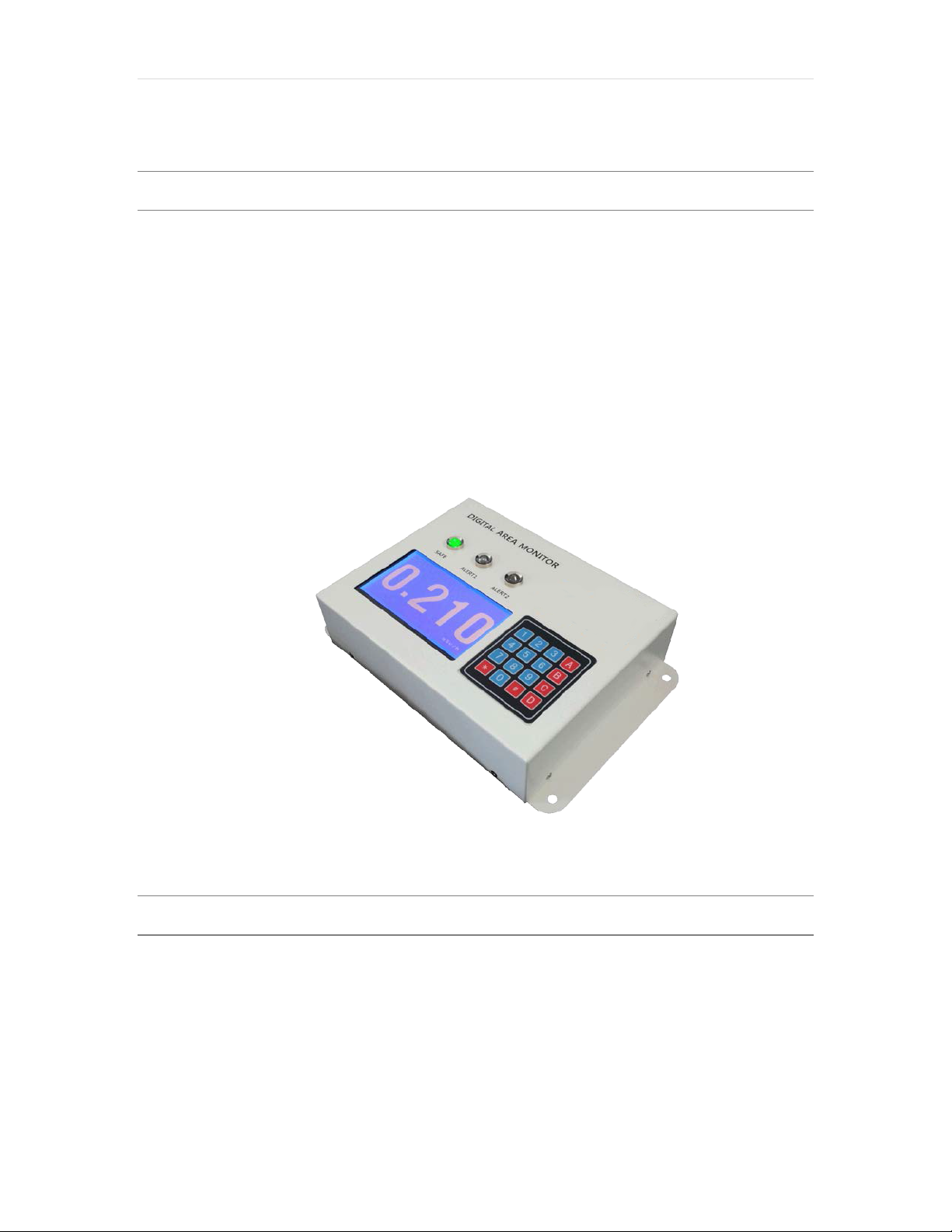
The following warnings and instructions are vital to the optimal operation of the BNC™
MODEL 960 unit and should be made readily accessible for reference. Follow these
warnings and instructions thoroughly to use the unit correctly and to protect the safety of
both the patients and the users.
Handling Instructions:
•The operation and servicing of the unit should only be handled by qualified/trained
personnel
•To keep measurement errors at a minimal, always verify the validity of any
measurement or test result.
•Adjacent or stacked use of the unit should only be done when necessary. In such
cases, configure the unit as it will be used and then verify normal operation.
Safety Hazard Warnings:
•It can be very hazardous to open the covers with the system plugged in on account
of high voltage inside the unit (high voltage in the detectors are up to 1000 Volts).
Be sure to refer all servicing to qualified/trained personnel.
Disposal Instructions:
•If/when disposing the unit: observe local and national regulations for the disposal of
units containing lead.
•If/when disposing the unit: observe local and national regulations for the disposal of
units containing a lithium battery.
•Do not use household of municipal waste collection services for disposal of electrical
and electronic equipment. EU countries require the use of separate recycling
collection services.
Caution:
•This equipment generates, uses and can radiate radio frequency energy and, if not
installed and used in accordance with the instructions, may cause harmful
interference to other devices in the vicinity. However, there is no guarantee that
interference will not occur in a particular installation. If this equipment does cause
harmful interference to other devices, which can be determined by turning the
equipment off and on, the user is encouraged to try to correct the interference by
one or more of the following measures:
Reorient or relocate the receiving device.

Page | 6
Increase the separation between the equipment.
Connect the equipment into an outlet on a circuit different from that to
which the other device(s) are connected.
Consult the manufacturer or field service technician for help.”If/when
disposing the unit: observe local and national regulations for the disposal of
units containing lead.
WARNING:
•External equipment intended for connection to signal input, signal output or other
connectors, shall comply with relevant EN Standard
•If, in doubt, contact qualified technician or your local representative.
CLASSIFICATION
•BNC™ MODEL 960 is comply with EN61326-1:2006, EN61000-3-
2_A1:2009+A2:2009, EN61000-3-3:2008 and EN61010-1:2010
LABELS
The label providing the system power requirements, contact information, MAC address and
serial number of the system is located at the right-side of the unit.
Figure 2. BNC™ MODEL 960 label

7 | Page
ENVIRONMENT REQUIREMENTS
Operational
To warrant reliability and accuracy of the instrument, the unit should be placed in a
surrounding environment consisting of the following:
•Temperatures range within +41°F to +100°F (+5°C to +38°C)
•Maximum relative humidity is 10% to 80%.
•A barometric pressure range of 27–31 inches of mercury (700–1,060 hPa).
•Lowest possible and most constant background radiation
Storage
To warrant maximum reliability, the instrument should be stored in an environment
consisting of the following:
•Temperatures are stable and range from -40°F to +140°F (-20°C to +60°C)
•The maximum relative humidity is 5% to 95%
•Barometric pressure is within a range of 27–31 inches of mercury (700-1,060 hPa).

Page | 8
CHAPTER 3. SETUP INSTRUCTION
SYSTEM COMPONENTS
BNC™ MODEL 960 and its components are shown in figure 3. The accessories are
needed depend on options. Accessories include DC adaptor, Ethernet cable and 3 way
strobe/horn with alarm LED and speaker.
Figure 3. BNC™ MODEL 960 and its components

9 | Page
INSTALLATION
BNC™ MODEL 960 is pre-configured and fully tested at the factory before being shipped.
Therefore, it is ready to operate by simply connecting the power and turn the switch on.
Figure 4 shows location of ports, keypad, display and alarm LEDs.
Figure 4. BNC™ MODEL 960 label
BNC™ MODEL 960 supports two power options. I.e., PoE (power of Ethernet) or DC.
Note: In case of using an external strobe/horn, PoE is not supported. Only DC power
option works.
Note: In case of PoE power option, make sure to use a PoE supporting hub.
Note: In case of “wall flush” installation, an in-wall mounting bracket and a cover are
provided. Installation example is shown in figure 5.

Page | 10
Figure 4. “Wall flush” installation example
USING KEYPAD
•Turn On message
When MODEL 960 is turned ON, it displays following message. “Background
Measurement in progress. Please wait…”
It measures background radiation for a given time (defined in configuration setup as
‘averaging time’).
Figure 5. BNC™ MODEL 960 turn on message. Background measurement procedure

11 | Page
•Access to configuration menu
Press ‘*’ on the keypad in order to access the configuration menu. The unit will ask 4
digit password as shown in figure 6.
Note: Factory preconfigured default password is 0000.
Figure 6. Access to the configuration menu example
•Configuration menu screen
MODEL 960 support 5 configurable parementers such as password, dose rate unit,
alarm threshold and averaging time. Figure 7 shows configuration menu screen.
0: Change password
1: Select dose rate unit displayed.
2: Set alarm threshold for ALERT1
3: Set alarm threshold for ALERT2
4: Set average interval time
5: Exit
When a number is pressed on the keypad from 0 to 5, it enters to a corresponding
configuration screen.

Page | 12
Figure 7. Configuration menu screen
•Changing password
Changing password example is shown in figure 8. Enter 4 digit number and reenter same
4 digit number to confirm. Then, press A for enter or B for cancel the change.
Figure 8. Password changing example
•Selecting dose rate unit displayed
MODEL 960 support dose rate unit of uSv/h, uR/h, CPS, CPM. Selecting a number
from the keypad. The factory preconfigured default unit is uSv/h.
Note: If dose rate exceed uSv/h (or uR/h), the system automatically change the
units to mSv/h or Sv/h (or mR/h or R/h).

13 | Page
Figure 9. Selecting dose rate unit.
•Setup alarm threshold
MODEL 960 support two alarm levels, i.e., ALERT1 and ALERT2.
Alarm threshold value can be from 1 to 100000 uSv/h. The default factory setup is 1
uSv/h. and 5 uSv/h for ALERT1 and ALERT2, respectively.
Note: the threshold values must be ALERT1 < ALERT2. Otherwise, the system
won’t accept the change.
Figure 10. setup alarm threshold example (ALERT1 case)
•Setup averaging interval time
In general, GM tube requires averaging radiation activity over certain time period to
average out spike-like signals which may cause false alarm.
The averaging time ranges from 30 to 300 second. The factory default setup is 30 sec.

Page | 14
Figure 11. Setup averaging time interval.
RELAY OUTPUT CONFIGURATION
MODEL 960 supports 3 relay output signals. i.e., normal, alert1 and alert2. It uses a DIN-
604 (6P) connector and its pin configuration is as follow:
•Normal (Green LED): #5
•ALERT1 (Yellow LED): #4
•ALERT2 (Red LED): #2
•Ground: #7

15 | Page
Figure 12. Relay output pin configuration: DIN-604(6P)
STROBE & HORN CONFIGURATION
External strobe & horn (D-SUB 9F) configuration is shown in figure 13. Its pin
configuration is as follow:
•Normal (Green LED): #5
•ALETR1 (Yellow LED): #4
•ALETR2 (Red LED): #6
•Ground: #2

Page | 16
Figure 13. Strobe & Horn pin configuration.
The MODEL 960’s external Strobe & Horn has 3 way LED with speaker. And it is sync
with status LED of main body. Figure 14 shows normal (green LED), alert1 (yellow
LED) and alert2 (red LED).
Figure 14. Strobe & Horn pin configuration.

17 | Page
CHAPTER 4. APPLICATION SOFTWARE
NOTE: Application software is an optional feature for the case that remote
control and/or monitoring is required via Ethernet.
NETWORK SECURITY (FIRE WALL)
MODEL 960 uses both UDP and TCP network protocol. If it may not work properly
because of OS SECURITY. Please make following changes.
Note: Window security setup is out of program privilege, so if you have any problem,
ask for computer manager and network manager.
•To Configure Network Security
1. Select control panel and then run Fire wall.
Figure 15. Windows control panel
2. Select Allowed Apps.

Page | 18
Figure 16. Fire wall configuration window
3. Select Allow another app.
Figure 17. Exception configuration window

19 | Page
4. Click on <browser> at Window then run AM100 execution file in MODEL 960
folder.
Figure 18. Program execution file selection
Note: Fire wall setup screen might be different depend on Windows OS version.
Note: If you have any problem in Fire wall setup, ask for computer manager and
network manager.

Page | 20
APPLICATION SOFTWARE
•Login procedure
When running the software, login window appears as shown in figure 19. Enter valid ID
with password.
Factory preconfigured ID and password is ‘admin’ and ‘admin’, respectively.
Note: The first time to login as admin, Please change the password for security.
Note: Without password, you couldn’t run the program so you must remember the
password.
Note: If you forget about the Password, please re-install the program.
Figure 19. Login window
The main screen is shown in figure 20. It is divided into 5 fields, i.e. main menu bar, detector
status, real-time activity, date/time and event log.
Details of each function and usage is described in following sub chapters.
Table of contents
Other BNC Laboratory Equipment manuals