Bo EDIN AB GBH 2400 Professional User manual

Robert Bosch GmbH
Power Tools Division
70764 Leinfelden-Echterdingen
GERMANY
www.bosch-pt.com
1 609 92A 29V (2016.04) PS / 193
GBH 2400 Professional
de Originalbetriebsanleitung
en Original instructions
fr Notice originale
es Manual original
pt Manual original
it Istruzioni originali
nl Oorspronkelijke
gebruiksaanwijzing
da Original brugsanvisning
sv Bruksanvisning i original
no Original driftsinstruks
fi Alkuperäiset ohjeet
el Πρωτότυπο οδηγιών χρήσης
tr Orijinal işletme talimatı
pl Instrukcja oryginalna
cs Původní návod k používání
sk Pôvodný návod na použitie
hu Eredeti használati utasítás
ru Оригинальное руководство
по эксплуатации
uk Оригінальна інструкція з
експлуатації
kk Пайдалану нұсқаулығының
түпнұсқасы
ro Instrucţiuni originale
bg Оригинална инструкция
mk Оригинално упатство за работа
sr Originalno uputstvo za rad
sl Izvirna navodila
hr Originalne upute za rad
et Algupärane kasutusjuhend
lv Instrukcijas oriģinālvalodā
lt Originali instrukcija
ko 사용 설명서 원본
ar
fa
ςТЎϩХʉ ЌТϾϦφЍʉ ʌμВТЎϺυ
ΖЎϩʉ ˒μВЖЙʉʓ ИͳϞφЁʑ
OBJ_BUCH-861-006.book Page 1 Tuesday, April 5, 2016 4:55 PM
2|
1 609 92A 29V | (5.4.16) Bosch Power Tools
Deutsch. . . . . . . . . . . . . . . . . . .. . . . . . . . . . . .. . . . . . . . . . Seite 6
English . . . . . . . . . . . . . . . . . . .. . . . . . . . . . . .. . . . . . . . . . .Page 11
Français . . . . . . . .. . . . . . . . . . . . . . . . . . . . . . . . . . . .. . . . .Page 17
Español. . . . . . . . . . . . . . . . . . . . . . . . . . . .. . . . . . . . . . . . Página 23
Português . . . . . . . . . . . . .. . . . . . . . . . . . . . . .. . . . . . . . . Página 29
Italiano . . . . . .. . . . . . . . . . . . .. . . . . . . . . . . . . . .. . . . . . Pagina 35
Nederlands. . . . . . . . . . . . . . . . . . . . . .. . . . . . . . . . . .. . . Pagina 41
Dansk . . . . . . . . . . . . . . . . . . . . . . . . . . . . . . . . . . . . . .. . . . . Side 47
Svenska . . . . . . . . . . . . . . . . . . . . . . . . . . .. . . . . . . . . . . .. . Sida 52
Norsk. . . . . . . . . . .. . . . . . . . . . . . .. . . . . . . . . . . .. . . . . . . . Side 57
Suomi . . . . . . . . . . . . . . . . . . . . . . . . . .. . . . . . . . . . . .. . . . . Sivu 62
Ελληνικά . . . . . . . . . . . . . . . . . . . . . . . . . . . . . .. . . . . . . . . Σελίδα 67
Türkçe. . . . . . . . . .. . . . . . . . . . . . . . . .. . . . . . . . . . . .. . . . Sayfa 73
Polski . . . . . . . . . . . . .. . . . . . . . . . . . .. . . . . . . . . . . . . . . Strona 79
Česky . . . . . . . . . . . . . . . . . . . .. . . . . . . . . . . . . . . . . . . . . Strana 85
Slovensky . . . . . . . . . . . . . . . . . . . . . . .. . . . . . . . . . . .. . . Strana 90
Magyar . . . . . . . . . . . . . . . . . . . . . . . . .. . . . . . . . . . . . . . . . Oldal 95
Русский . . . . . . . . . . . . . .. . . . . . . . . . . . .. . . . . . . . . Страница 102
Українська . . . . . . . . . . . . . . . . . . .. . . . . . . . . . . .. . . . Сторінка 109
Қазақша . . . . . . . . . . . . . . . . . . . . . . . . . . . . . .. . . . . . . . . . . . Бет 115
Română. . . . . . . . . . . . . . . . . . . . . . . . . . . .. . . . . . . . . . . . Pagina 121
Български . . . . . . . . . . . . . . . . . . .. . . . . . . . . . . . . . . Страница 127
Македонски . . . . . . . . . . . . . . . . . . . . . . . . . .. . . . . . . . . Страна 133
Srpski . . . . . . . . . . . . . . . . . . . .. . . . . . . . . . . .. . . . . . . . . Strana 139
Slovensko. . . . . . . . . . . . . . . . . . . . . . . . . .. . . . . . . . . . . .. Stran 144
Hrvatski. . . . . . . . . . . . . . . . . . . . . . . . .. . . . . . . . . . . .. .Stranica 149
Eesti . . . . . . . . . . . . . . . . . . . . . . . . . . . . . .. . . . . . . . . . Lehekülg 154
Latviešu . . . . . . . . . . . . . .. . . . . . . . . . . . .. . . . . . . . . . .Lappuse 159
Lietuviškai. . . . . . . . . . . . . . . . . . . . . . . . . .. . . . . . . . . . .Puslapis 165
한국어 . . . . . . . . . . . . . . . . . . . . . . . . 페이지 171
. . . . . . . . . . . . . . . . . . . . . . . . . . . . . . 182
. . . . . . . . . . . . . . . . . . . . . . . . . . . . . . 189
. . . . . . . . . . .. . . . . . . . . . . . . . . . . . . . . . . . . . . . . . . . . . . . . I
OBJ_BUCH-861-006.book Page 2 Tuesday, April 5, 2016 4:55 PM
3|
1 609 92A 29V | (5.4.16) Bosch Power Tools
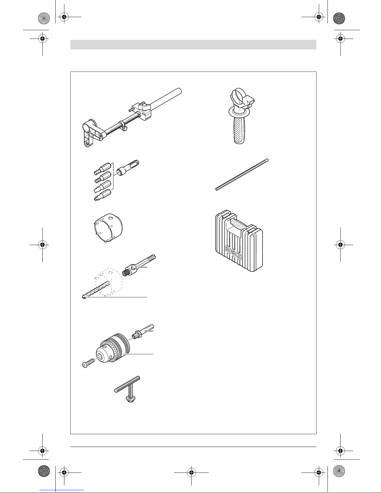
1 607 000 173
2 608 550 057
SDS-plus
2 608 596 157
(Ø 8 mm)
2 602 025 141
1 613 001 010
2 605 438 098
2 608 550 074 (Ø 40 mm)
2 608 550 075 (Ø 50 mm)
2 608 550 076 (Ø 68 mm)
1 617 000 132
SDS-plus
1 608 571 062
Ø 1,5–13 mm
1 607 950 045
2 607 000 207
OBJ_BUCH-861-006.book Page 3 Tuesday, April 5, 2016 4:55 PM
1 609 92A 29V | (5.4.16) Bosch Power Tools
4|
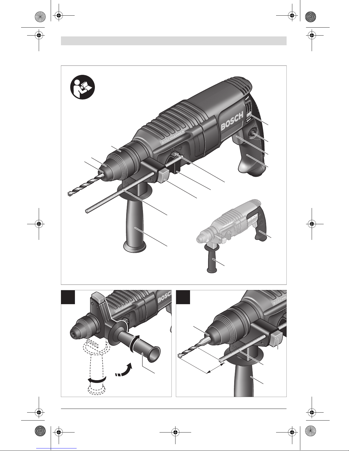
12 X
1
11
10
12
2
1
3
4
5
6
7
7
8
9
10
11
12
12
B
A
GBH 2400
OBJ_BUCH-861-006.book Page 4 Tuesday, April 5, 2016 4:55 PM

5|
1 609 92A 29V | (5.4.16) Bosch Power Tools
X
17 18 19 20 21
15
3
14
13
16 12
10
3
22
3
HG
FE
D
C
OBJ_BUCH-861-006.book Page 5 Tuesday, April 5, 2016 4:55 PM
Table of contents
Languages:
Popular Rotary Hammer manuals by other brands


Makita
Makita DHR280 instruction manual

BorMann
BorMann BPH7000 Translation of the original instructions

Metabo HPT
Metabo HPT DH 3628DD Safety instructions and instruction manual

Black & Decker
Black & Decker KD650 manual

Bosch
Bosch GBH Professional 2-20 DRE Original instructions

Makita
Makita HR2020 instruction manual