Boardcon EM3288 User manual
EM3288 Hardware Manual
V2.0
www.boardcon.com
Boardcon Embedded Design

1
Customize the embedded system based on YourIdea
1. Introduction
1.1. About this Manual
This manual is intended to provide the user with an overview of the board and benefits, complete
features specifications, and set up procedures. It contains important safety information as well.
1.2. Feedback and Update to this Manual
To help our customers make the most of our products, we are continually making additional and
updated resources available on the Boardcon website (www.boardcon.com , www.armdesigner.com).
These include manuals, application notes, programming examples, and updated software and
hardware. Check in periodically to see what’s new!
When we are prioritizing work on these updated resources, feedback from customers is the number
one influence, If you have questions, comments, or concerns about your product or project, please
no hesitate to contact us at support@armdesigner.com.
1.3. Limited Warranty
Boardcon warrants this product to be free of defects in material and workmanship for a period of one
year from date of buy. During this warranty period Boardcon will repair or replace the defective unit
in accordance with the following process:
A copy of the original invoice must be included when returning the defective unit to Boardcon. This
limited warranty does not cover damages resulting from lighting or other power surges, misuse,
abuse, abnormal conditions of operation, or attempts to alter or modify the function of the product.
This warranty is limited to the repair or replacement of the defective unit. In no event shall Boardcon
be liable or responsible for any loss or damages, including but not limited to any lost profits, incidental
or consequential damages, loss of business, or anticipatory profits arising from the use or inability
to use this product.
Repairs make after the expiration of the warranty period are subject to a repair charge and the cost
of return shipping. Please contact Boardcon to arrange for any repair service and to obtain repair
charge information.

2
Customize the embedded system based on YourIdea
Content
1 EM3288 Introduction ......................................................................................................................3
1.1 Summary..............................................................................................................................3
1.2 Rockchip RK3288 Features .................................................................................................3
1.3 EM3288 Specifications.........................................................................................................4
1.4 PCB Dimension ....................................................................................................................5
1.5 Block Diagram ......................................................................................................................6
1.6 CPU Introduction ..................................................................................................................6
2 Peripherals Introduction .................................................................................................................9
2.1 Power (P6, J17) ...................................................................................................................9
2.2 Ethernet (JP1) ....................................................................................................................10
2.3 USB HOST (P2, P3)...........................................................................................................11
2.4 USB OTG (J8) ....................................................................................................................12
2.5 Micro SD (J1) .....................................................................................................................12
2.6 HDMI (PH1)........................................................................................................................13
2.7 Audio I/O (J6, J7, MIC1).....................................................................................................13
2.8 VGA (J20)...........................................................................................................................14
2.9 LVDS (CON3).....................................................................................................................15
2.10 TTL LCD (J21)..................................................................................................................15
2.11 MIPI (CON5).....................................................................................................................16
2.12 GPS (MU4).......................................................................................................................17
2.13 WiFi&Bluetooth (U11).......................................................................................................18
2.14 Debug UART (J10)...........................................................................................................19
2.15 GPIO (CON4) ...................................................................................................................19
2.16 Control (J2) ......................................................................................................................21
2.17 Buttons (K1, K2) ...............................................................................................................21
2.18 4G (CON2) .......................................................................................................................21
2.19 SATA & SATA_Power (J14, J18) ......................................................................................23
2.20 RTC (BT1) ........................................................................................................................23
3 Product Configurations .................................................................................................................24
3.1 Standard Contents .............................................................................................................24
3.2 Optional Parts ....................................................................................................................24

3
Customize the embedded system based on YourIdea
1 EM3288 Introduction
This document (V2) is based on EM3288 V7(MINI3288 version: V4).
1.1 Summary
EM3288 is based on the Rockchip RK3288, Quad Core Cortex-A17 @1.8GHz. RK3288 is powerful
on multithreaded computing operation, graphics processing and video decoding ability. It supports
Mali-T760 MP4 Graphics Processing, OpenGL ES1.1/2.0/3.0, OpenVG1.1, OpenCL, Directx11, and
can 4Kx2K achieve 4kx2k H.264 and 10 bits of H.265 video decoding, 500% performance boost
over Mali-400. On display aspects, RK3288 supports up to 18Gbps Data transmission rate and
4Kx2K@60Hz Video resolution.
EM3288 is provided with full ready-to-run Android7.1.2 and Ubuntu SW packages and
comprehensive user manual and designing guide.
1.2 Rockchip RK3288 Features
⚫CPU
Quad-Core Cortex-A17, up to 1.8GHz
⚫GPU
Mali-T764 GPU, Supports AFBC (ARM Frame Buffer Compression)
- Support OpenGL ES 1.1/2.0/3.1, OpenCL, DirectX9.3
- High performance dedicated 2D processor
⚫Multi-Media
4K 10bits H265/H264 video decoders
- 1080P other video decoders (VC-1, MPEG-1/2/4, VP8)
- 1080P video encoder for H.264 and VP8
- Video post processor: de-interlace, de-noise, enhancement for edge/detail/color
⚫Display
Support RGB/Dual LVDS/Dual MIPI-DSI/eDP interface, up to 3840*2160 resolution
HDMI 2.0 for 4K@60Hz with HDCP 1.4/2.2
⚫Security
- ARM TrustZone (TEE), Secure Video Path, Cipher Engine, Secure boot
⚫Memory
- Dual-channel 64bit DDR3-1333/DDR3L-1333/LPDDR2-1066
- Support MLC NAND, eMMC 4.51
⚫Connectivity
- Embedded 13M ISP, MIPI CSI-2 and DVP interface
- Dual SDIO 3.0 interface
- TS in/CSA2.0, support DTV function
- Embed HDMI, Ethernet MAC, S/PDIF, USB, I2C, I2S, UART, SPI, PS2

4
Customize the embedded system based on YourIdea
1.3 EM3288 Specifications
Feature
Specifications
CPU
·Rockchip RK3288, Quad Core Cortex-A17 @ 1.8GHz
·28nm HKMG process
GPU
·ARM Mali-T764 GPU, with TE, ASTC, AFBC technology
·Support OpenGL ES1.1/2.0/3.0, OpenVG1.1, OpenCL, DirectX11
Memory
2GB DDR3
Flash
4G/8GB eMMC Flash
Power
5V/3A
USB
3x USB2.0 Host, 1x USB2.0 OTG
LCD
1x 40-pin LVDS:
- 10.1-inch 1280 x 800 LCD with multi-dot capacitive touchscreen;
- 7-inch 1024 x6 00 LCD with multi-dot capacitive touchscreen;
1x 40-pin TTL LCD connector
VGA
1x VGA connector. Automatically adjust according to display size
Ethernet
100/1000M, RJ45 interface. RTL8211E-VB-CG controller
Serial port
1x 3pin connector, for debug
HDMI
HDMI V2.0, up to 4Kx2K@60fps. Audio sync-output
Audio
3.5mm jacks, MIC. ES8388 audio codec
Power in
DC 5V/3A
Ethernet
Dual-USB
Host
USB Host
USB
OTG
Micro SD
HDMI
Audio out
Line in
MIC
VGA
LVDS
MIPI
RGB LCD
GPS
optional
WiFi&BT
Debug
GPIO
Control
Recover
Power
4G&GPS
optional
SIM
SATA
optional
SATA-Power
Li-battery
optional
RTC
5
Customize the embedded system based on YourIdea
SD card
1x Micro SD card slot
WiFi & Bluetooth
AP6236 module. WiFi - 2.4GHz, 802.11b/g/n. Bluetooth4.0.
4G
Quectel EC20, PCIe connector
GPS
SATES ST-91-U7
Camera
Supporting MIPI camera, and most of USB CMOS camera on the market,
RTC
Real Time Clock, powered by external lithium battery
Button
Power, Recover
GPIO
1x 8-pin Control, 1x 40-pin GPIO
Other interfaces
1x SATA, 1x SATA-Power, 1x SIM Card, 1x Lithium battery interface
Dimension
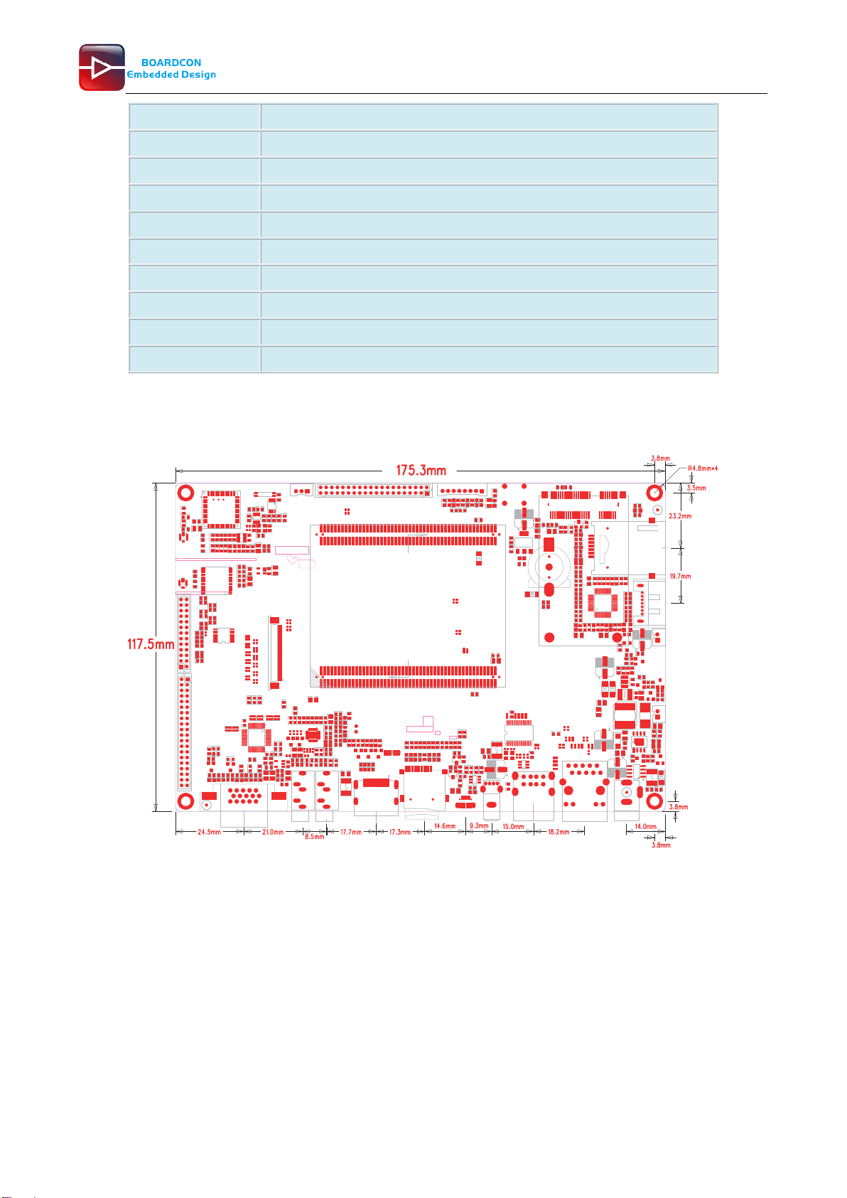
117.5 x 175.3mm
1.4 PCB Dimension
6
Customize the embedded system based on YourIdea
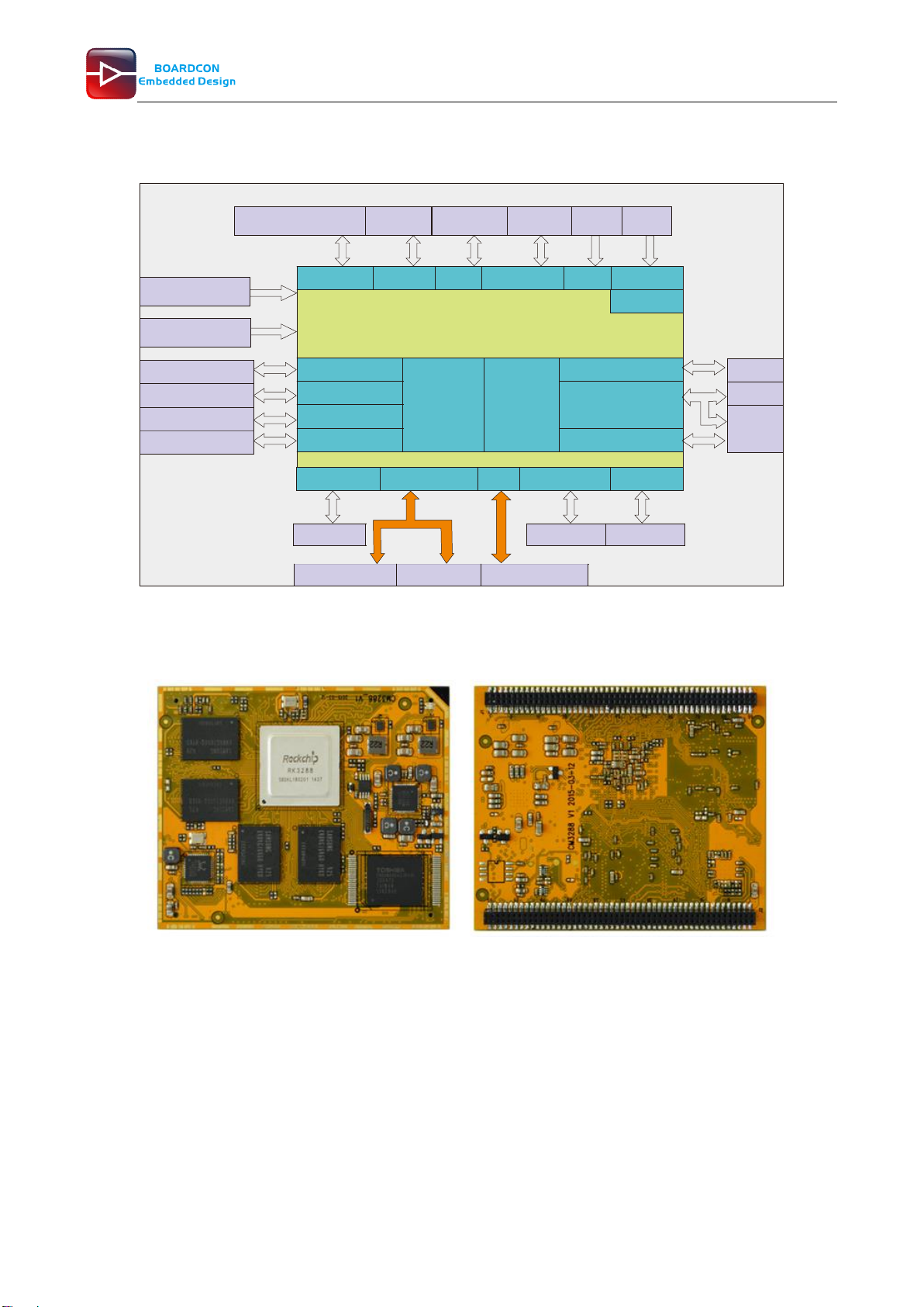
1.5 Block Diagram
1.6 CPU Introduction
Board Dimension
* Board size: 70mm x 58mm
* Pin to Pin space: 1.3mm
* Pin number: (J11+J12) x 100 = 200 pins
* Layer: 8 Layers, complying with EMS/EMI
EM3288 CPU Board
Rockchip3288 Cortex-A17 @1.8GHz
Micro USB
LCD&Touch MIPI PHY GPIO1 IRIN&GPIO2 Key_in Power_key
RTC
RGMII PHY
UART0 Dual
channel
DDR3 2GB
@200MHz
8GB eMMC
up to 32GB
HDMI1.4/2.0
UART2 I2C x 6
UART3
UART1&UART4 I2S
Power (Jack)
DC 5V/3A
40-pin FPC connector
40-pin LVDS header
26-pin
connector 8-pin
connector Recover
Lithium battery
Default not supported
LVDS/RGB
*40-pin
header Power
key
USB OTG2.0 2x USB Host2.0 NET0 SDMMC0 v3.0 SDIO0 v3.0
Mobile hard disk USB Host x 3 100/1000M RJ45
Av6256
Micro SD WIFI
Bluetooth
GPS
40-pin header
Debug serial port
3-pin connector
*
HDMI
VGA
Audio I/O
&
MIC
RGB
The same connector.
*
7
Customize the embedded system based on YourIdea
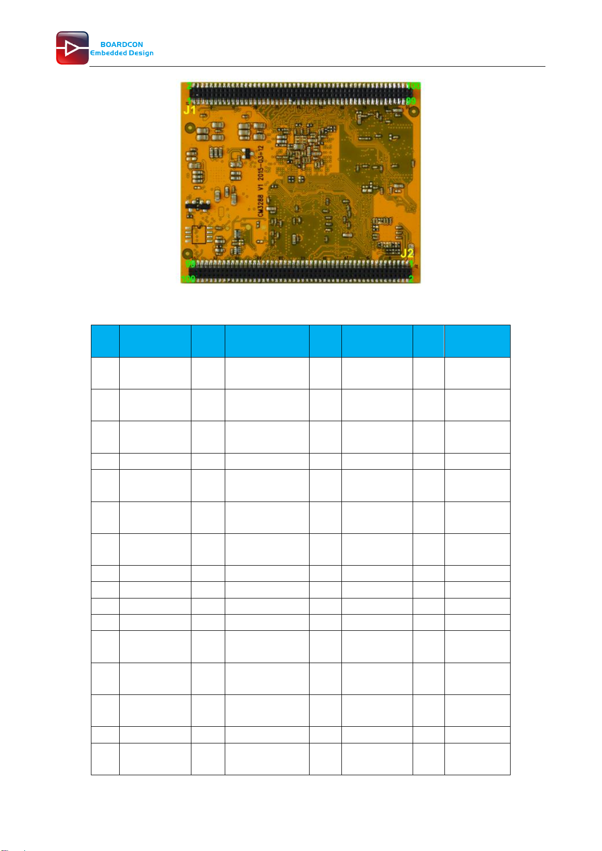
Pin Definition
Pin
(J1)
Signal
Pin
(J1)
Signal
Pin
(J2)
Signal
Pin
(J2)
Signal
1
TX_C
51
MIPI_TX/RX_D2
P
1
VCC_SYS
51
SPI0_UART
4_RXD
2
TX_0-
52
MIPI_TX/RX_D1
P
2
GND
52
SPI0_UART
4_TXD
3
TX_C+
53
MIPI_TX/RX_D3
P
3
VCC_SYS
53
GND
4
TX_0+
54
GND
4
GND
54
TS0_SYNC
5
GND
55
MIPI_TX/RX_D3
N
5
nRESET
55
UART1_CT
Sn
6
GND
56
DVP_PWR
6
MDI0+
56
UART1_RT
Sn
7
TX_1-
57
HSIC_STROBE
7
MDI1+
57
UART1_RX
_TS0_D0
8
TX_2-
58
HSIC_DATA
8
MDI0-
58
UART1_TX
9
TX_1+
59
GND
9
MDI1-
59
TS0_CLK
10
TX_2+
60
CIF_D1
10
IR_INT
60
TS0_VALID
11
HDMI_HPD
61
CIF_D0
11
MDI2+
61
TS0_ERR
12
HDMI_CEC
62
CIF_D3
12
MDI3+
62
GPIO7_B4_
U
13
I2C5_SDA_H
DMI
63
CIF_D2
13
MDI2-
63
SDMMC_CL
K
14
I2C5_SCL_H
DMI
64
CIF_D5
14
MDI3-
64
GND
15
GND
65
CIF_D4
15
GND
65
SDMMC_D0
16
LCD_VSYNC
66
CIF_D7
16
RST_KEY
66
SDMMC_C
MD

8
Customize the embedded system based on YourIdea
17
LCD_HSYNC
67
CIF_D6
17
SDIO0_CMD
67
SDMMC_D2
18
LCD_CLK
68
CIF_D9
18
SDIO0_D0
68
SDMMC_D1
19
LCD_DEN
69
CIF_D8
19
SDIO0_D1
69
SDMMC_DE
T
20
LCD_D0_LD0
P
70
CIF_PDN0
20
SDIO0_D2
70
SDMMC_D3
21
LCD_D1_LD0
N
71
CIF_D10
21
SDIO0_D3
71
SDMMC_P
WR
22
LCD_D2_LD1
P
72
CIF_HREF
22
SDIO0_CLK
72
GPIO0_B5_
D
23
LCD_D3_LD1
N
73
CIF_VSYNC
23
BT_WAKE
73
GND
24
LCD_D4_LD2
P
74
CIF_CLKOUT
24
SDIO0_WP
74
GPIO7_B7_
D
25
LCD_D5_LD2
N
75
CIF_CLKIN
25
WIFI_REG_O
N
75
I2S_SDI
26
LCD_D6_LD3
P
76
I2C3_SCL
26
BT_HOST_W
AKE
76
I2S_MCLK
27
LCD_D7_LD3
N
77
I2C3_SDA
27
WIFI_HOST_
WAKE
77
I2S_SCLK
28
LCD_D8_LD4
P
78
GND
28
BT_RST
78
I2S_LRCK_
RX
29
LCD_D9_LD4
N
79
GPIO0_B2_D
29
SPI2_CLK
79
I2S_LRCK_
TX
30
LCD_D10_LC
K0P
80
GPIO7_A3_D
30
SP2I_CSn0
80
I2S_SDO0
31
LCD_D11_LC
K0N
81
GPIO7_A6_U
31
SPI2_RXD
81
2S_SDO1
32
LCD_D12_LD
5P
82
GPIO0_A6_U
32
SPI2_TXD
82
I2S_SDO2
33
LCD_D13_LD
5N
83
LED0_AD0
33
OTG_VBUS_
DRV
83
I2S_SDO3
34
LCD_D14_LD
6P
84
LED1_AD1
34
HOST_VBUS
_DRV
84
SPDIF_TX
35
LCD_D15_LD
6N
85
VCC_LAN
35
UART0_RX
85
I2C2_SDA
36
LCD_D16_LD
7P
86
PS2_DATA
36
UART0_TX
86
GND
37
LCD_D17_LD
7N
87
PS2_CLK
37
GND
87
I2C1_SDA
38
LCD_D18_LD
8P
88
ADC0_IN
38
UART0_CTS
88
I2C2_SCL
9
Customize the embedded system based on YourIdea
39
LCD_D19_LD
8N
89
GPIO0_A7_U
39
OTG_DM
89
I2C4_SDA
40
LCD_D20_LD
9P
90
ADC1_IN
40
UART0_RTS
90
I2C1_SCL
41
LCD_D21_LD
9N
91
VCCIO_SD
41
OTG_DP
91
UART2_RX
42
LCD_D22_LC
K1P
92
ADC2_IN
42
OTG_ID
92
I2C4_SCL
43
LCD_D23_LC
K1N
93
VCC_CAM
43
HOST1_DM
93
UART3_RX
44
GND
94
VCCA_33
44
OTG_DET
94
UART2_TX
45
MIPI_TX/RX_
CLKN
95
VCC_18
45
HOST1_DP
95
UART3_RT
Sn
46
MIPI_TX/RX_
D0P
96
VCC_RTC
46
HOST2_DM
96
UART3_TX
47
MIPI_TX/RX_
CLKP
97
VCC_IO
47
SPI0_CSn0
97
PWM1
48
MIPI_TX/RX_
D0N
98
GND
48
HOST2_DP
98
UART3_CT
Sn
49
MIPI_TX/RX_
D2N
99
VCC_IO
49
SPI0_CLK
99
PWR_KEY
50
MIPI_TX/RX_
D1N
100
GND
50
GND
100
GPIO7_C5_
D
2 Peripherals Introduction
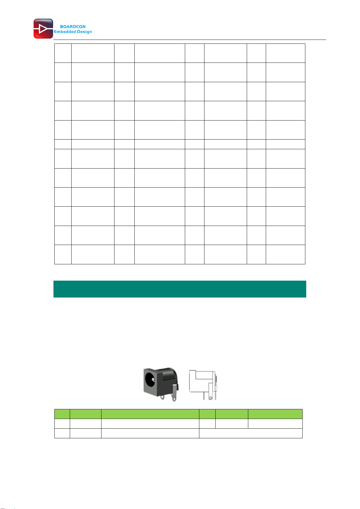
2.1 Power (P6, J17)
EM3288 Power Supply – 5V DC power supply or external Li+ battery
⚫5V/3A DC power supply (P6)
Pin
Signal
Description
Pin
Signal
Description
1
VDD5V
Main power supply. DC 5V power in
2
GND
Ground
3
GND
Ground
⚫Lithium battery (J17)
EM3288 provides an external Li-battery interface. It is a Reserved interface that function not
1
2
3

10
Customize the embedded system based on YourIdea
supported currently.
Pin
Signal
Description
Pin
Signal
Description
1
GND
Ground
2
VBAT
Li-Battery
2.2 Ethernet (JP1)
RK3288 has integrated Gigabit Ethernet MAC. EM3288 adopts RTL8211E as the Ethernet chip.
RJ45 connector
Feature
⚫Supports 10/100/1000-Mbps data transfer rates with the RGMII interfaces
⚫Supports both full-duplex and half-duplex operation
⚫Supports IEEE 802.1Q VLAN tag detection for reception frames
Pin
Signal
Description
Pin
Signal
Description
1
COM
Common
2
MDI0P
Bi-directional
transmit/receive pair 0
3
MDI0N
Bi-directional
transmit/receive pair 0
4
MDI1P
Bi-directional
transmit/receive pair 1
5
MDI2P
Bi-directional
transmit/receive pair2
6
MDI2N
Bi-directional
transmit/receive pair2
7
MDI1N
Bi-directional
transmit/receive pair 1
8
MDI3P
Bi-directional
transmit/receive pair 3
9
MDI3N
Bi-directional
transmit/receive pair 3
10
GND
Ground
11
VCC_LAN
3.3V
12
LINK
Detect link
13
GND
Ground
14
SPEED
Detect speed
15
GND
Ground
16
GND
Ground
2 1
10 9
1
2
11
12
13
14
11
Customize the embedded system based on YourIdea
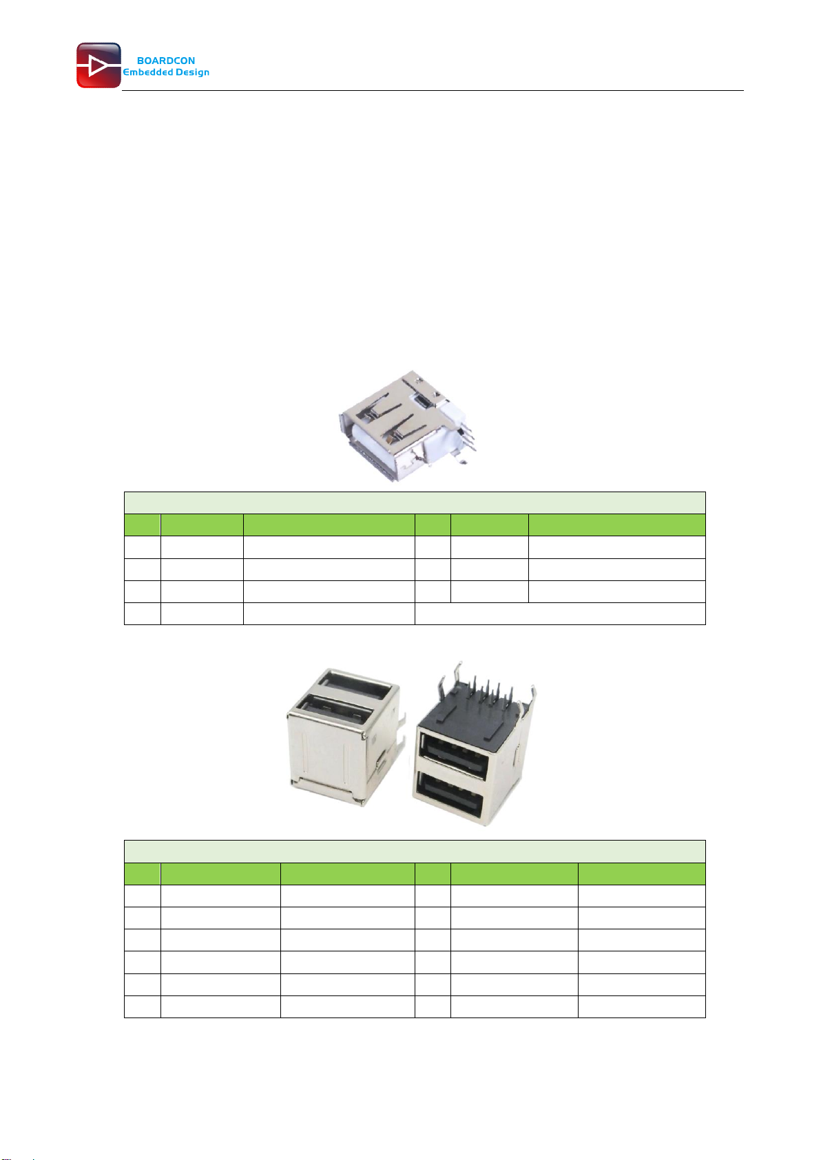
2.3 USB HOST (P2, P3)
EM3288 provides 3x USB2.0 Host. One is a single USB (P2), and the other is a double-USB (P3).
The 3-ch USB HOST interfaces are extended by AU6256 which is a fully compliant with the USB 2.0
hub specification and is designed to work with USB host as a high-speed hub.
Feature
⚫Compatible with USB Host2.0 specification
⚫Supports high-speed (480Mbps), full-speed (12Mbps) and low-speed (1.5Mbps) mode
⚫Supports automatic switching between bus- and self-powered modes
⚫Provides 16 host mode channels
⚫Support periodic out channel in host mode
Single-Host (P2)
Pin
Signal
Description
Pin
Signal
Description
1
VCC_5V
USB Power. DC 5V
2
USB_DM2
USB data-
3
USB_DP2
USB Data+
4
GND
Ground
5
GND
Ground
6
GND
Ground
7
GND
Ground
Double- Host (P3)
Pin
Signal
Description
Pin
Signal
Description
1
VCC_USB
USB Power. DC 5V
2
USB_DM3
USB data-
3
USB_DP3
USB Data+
4
GND
Ground
5
VCC_USB
USB Power. DC 5V
6
USB_DM4
USB data-
7
USB_DP4
USB Data+
8
GND
Ground
9
GND
Ground
10
GND
Ground
11
GND
Ground
12
GND
Ground
1
4
5
6
7
1
5
8
4

12
Customize the embedded system based on YourIdea
2.4 USB OTG (J8)
EM3288 OTG is a Micro USB2.0 port, it is used to download image and ADB transfer file.
Feature
⚫Compatible with USB OTG2.0 specification
⚫Supports USB 2.0 High Speed (480Mbps), Full Speed (12Mbps) and Low Speed (1.5Mbps)
operation in host mode
⚫Supports USB 2.0 High Speed (480 Mbps) and Full Speed (12 Mbps) operation in peripheral
mode.
⚫Hardware support for OTG signaling, session request protocol, and host negotiation protocol.
Pin
Signal
Description
Pin
Signal
Description
1
OTG_DET
OTG detection
2
OTG_DM
OTG data -
3
OTG_DP
OTG data+
4
OTG_ID
OTG ID indicator
5
GND
Ground
2.5 Micro SD (J1)
The Micro SD card is used as an external storage device. The MMC controller interface supports up
to 4-bit transfer modes. MMC is always accessible through the carrier board interface. It does not
support hot-plug.
Pin
Signal
Description
Pin
Signal
Description
1
SDMMC_D2
SD/MMC data2
2
SDMMC_D3
SD/MMC data3
3
SDMMC_CMD
SD/MMC command
signal
4
VCCIO_SD
3.3V
5
SDMMC_CLK
SD/MMC clock
6
GND
Ground
7
SDMMC_D0
SD/MMC data0
8
SDMMC_D1
SD/MMC data1
9
SDMMC_DET
SD/MMC detect signal
1
5
9
1

13
Customize the embedded system based on YourIdea
2.6 HDMI (PH1)
EM3288 HDMI2.0 supports maximum 4Kx2K display, and it also enables HDMI/LCD audio and video
synchronization output. The HDMI interface is the regular 19pins HDMI type A, with width 13.9mm
and thickness 4.45mm.
Pin
Signal
Description
Pin
Signal
Description
1
TX_2+
HDMI data 2 pair
2
GND
Ground
3
TX_2-
4
TX_1+
HDMI data 1 pair
5
GND
Ground
6
TX_1-
7
TX_0+
HDMI data 0 pair
8
GND
Ground
9
TX_0-
10
TX_C+
HDMI clock pair
11
GND
Ground
12
TX_C-
13
HDMI_CEC
Consumer
electronics control
14
NC
Not connect
15
HDMI_SCL
HDMI serial clock
16
HDMI_SDA
HDMI serial data
17
GND
Ground
18
HDMI_VCC
5V
19
HDMI_HPD
Hot Plug Detect
20
GND
Ground
21
GND
Ground
22
GND
Ground
23
GND
Ground
2.7 Audio I/O (J6, J7, MIC1)
The EM3288 adopts audio codec ES8388, provides stereo audio output (Green, 3.5mm audio jack)
and line in (Pink, 3.5mm audio jack).
Features
⚫Low power
⚫Integrated ADC and DAC
⚫IIS transfer audio data
⚫Stereo output, support recording
1
19
1
2
34
5
1
2
34
5Audio out
Line in
14
Customize the embedded system based on YourIdea
Line in (J6)
Pin
Signal
Description
Pin
Signal
Description
1
GND
Ground
2
RIN2
Right Channel input
3
RIN2
Right Channel input
4
LIN2
Left Channel input
5
LIN2
Left Channel input
Audio out (J7)
Pin
Signal
Description
Pin
Signal
Description
1
GND
Ground
2
HP_RO
Right Channel Headphone
Output
3
AROUT
Right Channel Headphone
Output
4
ALOUT
Left Channel Headphone
Output
5
HP_LO
Left Channel Headphone Output
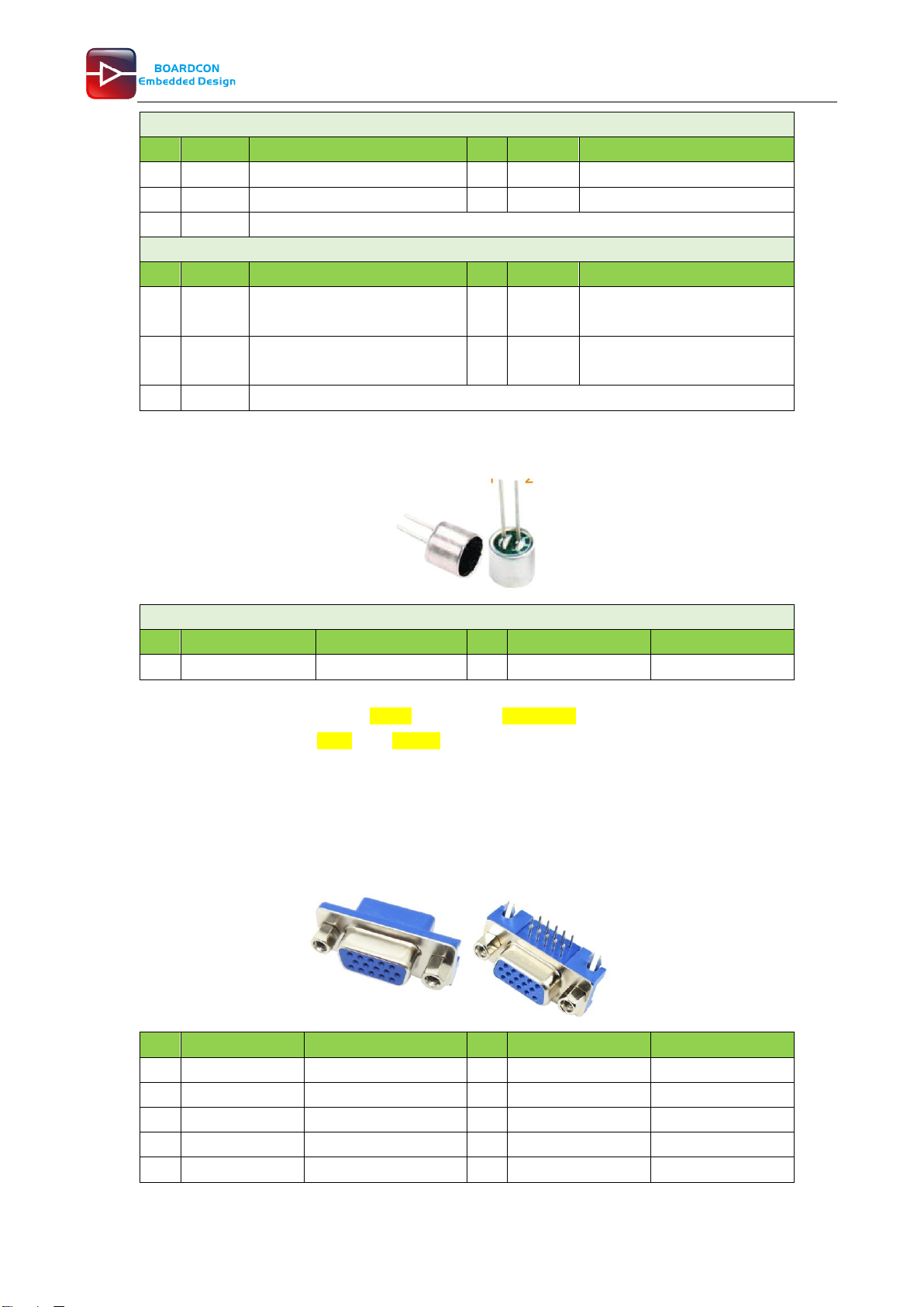
The Microphone MIC1 model is WM_64BC MIC/F6/DIP. It is used for recording.
MIC1
Pin
Signal
Description
Pin
Signal
Description
1
MIC1P
Command signal
2
MIC1N
Ground
Note:
1. The audio default output from HDMI. No sound in headphone if not remove HDMI.
2. Default recording via MIC1 if the Line_in jack is not plugged in.
2.8 VGA (J20)
EM3288 adopts standard 15-pin female VGA connector, and SDA7123 3-Channel 10 Digit Video
D/A converter.
Pin
Signal
Description
Pin
Signal
Description
1
IOR
Video red
2
IOG
Video green
3
IOB
Video blue
4
NC
Not connect
5
GND
Ground
6
GND
Ground
7
GND
GND
8
GND
GND
9
VCC5V
DC 5V
10
GND
Ground
1 2
1
11
15
5
1
5
15
11
15
Customize the embedded system based on YourIdea
11
NC
Not connect
12
VGA_OUT_SDA
Serial Data
13
LCD_HSYNC
LCD Horizontal Sync
14
LCD_VSYNC
LCD Vertical Sync
15
GND
GND
2.9 LVDS (CON3)
EM3288 supports 10.1-inch HD capacitive LCD, up to 1280 x 800 resolution.
Feature
⚫Comply with the TIA/EIA-644-A LVDS standard
⚫Combine LVTTL IO, support LVDS/LVTTL data output
⚫Support reference clock frequency range from 10MHz to 148.5MHz
⚫Support LVDS RGB 30/24/18bits color data transfer
⚫Support VESA/JEIDA LVDS data format transfer
⚫Support MSB mode and LSB mode data transfer
Pin
Signal
Pin
Signal
Pin
Signal
Pin
Signal
1
VCC5V
2
VCC5V
3
GND
4
GND
5
VCC_IO
6
VCC_IO
7
GND
8
GND
9
I2C4_SCL
10
I2C4_SDA
11
TOUCH_RST
12
TOUCH_INT
13
LVDS_EN
14
LVDS_PWM
15
GND
16
GND
17
LCK1P
18
LCK1N
19
GND
20
GND
21
LD8P
22
LD8N
23
LD7P
24
LD7N
25
LD6P
26
LD6N
27
LD5P
28
LD5N
29
LCK0P
30
LCK0N
31
GND
32
GND
33
LD3P
34
LD3N
35
LD2P
36
LD2N
37
LD1P
38
LD1N
39
LD0P
40
LD0N
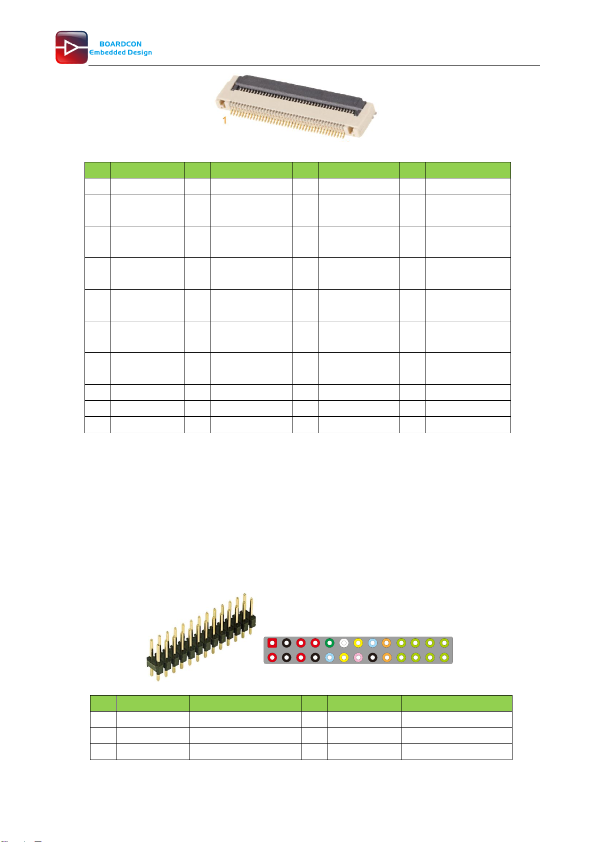
2.10 TTL LCD (J21)
J21 is a 40-pin FPC connector for TTL LCD.
1 3 57 9 11 13 15 17 19 21 23 25
2 4 6 8 10 12 14 16 18 20 22 24 26
21 23 25 27 29 31 33 35 37 39
28 30 32 34 36 38 40
16
Customize the embedded system based on YourIdea
Pin
Signal
Pin
Signal
Pin
Signal
Pin
Signal
1
VCC5V
2
VCC5V
3
LCD_D0_LD0P
4
LCD_D1_LD0N
5
LCD_D2_LD1
P
6
CD_D3_LD1N
7
LCD_D4_LD2P
8
LCD_D5_LD2N
9
LCD_D6_LD3
P
10
LCD_D7_LD3N
11
GND
12
LCD_D8_LD4P
13
LCD_D9_LD4
N
14
LCD_D10_LCK0
P
15
LCD_D11_LCK
0N
16
LCD_D12_LD5P
17
LCD_D13_LD
5N
18
LCD_D14_LD6P
19
LCD_D15_LD6
N
20
GND
21
LCD_D16_LD
7P
22
LCD_D17_LD7
N
23
LCD_D18_LD8
P
24
LCD_D19_LD8N
25
LCD_D20_LD
9P
26
LCD_D21_LD9
N
27
LCD_D22_LCK
1P
28
LCD_D23_LCK1
N
29
GND
30
LVDS_PWM
31
GND
32
GND
33
LCD_DEN
34
LCD_VSYNC
35
LCD_HSYNC
36
LCD_CLK
37
TSXM
38
TSXP
39
TSYM
40
TSYP
2.11 MIPI (CON5)
EM3288 supports MIPI Camera.
Features
⚫Embedded 3 MIPI PHY, MIPI 0 only for TX, MIPI 1 for TX and RX, MIPI 2 only for RX
⚫Support 4 data lane, providing up to 6Gbps data rate
⚫Support 1080p@60fps output
⚫Lane operation ranging from 80 Mbps to 1.5Gbps in forward direction.
Pin
Signal
Description
Pin
Signal
Description
1
VCC5V
DC 5V
2
VCC5V
DC 5V
3
GND
Ground
4
GND
Ground
5
VCC_IO
DC 3.3V
6
VCC_IO
DC 3.3V
1
40
13 5 7 9 11 13 15 17 19 21 23 25
24 6 8 10 12 14 16 18 20 22 24 26

17
Customize the embedded system based on YourIdea
7
VCCA_18
DC 1.8V
8
GND
Ground
9
LCD1_BL
Backlight
10
LCD1_BL_EN
Backlight enable
11
CIF_CLKOUT
Camera clock
12
I2C3_SCL
I2C clock line
13
I2C3_SDA
I2c date line
14
TOUCH_RST
Touch screen reset
15
TOUCH_INT
Touch screen int
16
GND
Ground
17
CLKN
MIPI clock -
18
CLKP
MIPI clock +
19
D0N
Negative Transmission
Data of Pixel0
20
D0P
Positive Transmission
Data of Pixel0
21
D1N
Negative Transmission
Data of Pixel1
22
D1P
Positive Transmission
Data of Pixel1
23
D2N
Negative Transmission
Data of Pixel2
24
D2P
Positive Transmission
Data of Pixel2
25
D3N
Negative Transmission
Data of Pixel3
26
D3P
Positive Transmission
Data of Pixel3
2.12 GPS (MU4)
The GPS module (Model: ST-91-U7) uses ublox 7 chipset which is high performance u-blox 7 multi-
GNSS (GPS, GLONASS, QZSS, SBAS – Galileo and Compass ready) position engine delivers
exceptional sensitivity and acquisition times.
Features
⚫Ublox 7 high performance and low power consumption GPS Chipset
⚫Very high sensitivity (Tracking Sensitivity: -162dBm)
⚫Extremely fast TTFF (Time to First Fix) at low signal level
⚫Two serial port: UART, I2C
⚫Built-in LNA
⚫A-GPS Support
⚫Exceptional jamming immunity
⚫Support NMEA 0183 and ublox binary protocol
⚫Channels: 56
⚫Available Baud: 9,600 bps
⚫The antenna band is 1575.42MHZ; Voltage: 3.0-5.0V
Pin
Signal
Description
Pin
Signal
Description
1
GND
Ground
2
GPS_UART3_RX
UART3 receive
3
GPS_UART3_TX
UART3 transmit
4
NC
Not connect
5
NC
Not connect
6
VCC_RTC
Backup voltage
19
1018
18
Customize the embedded system based on YourIdea
supply
7
GPSVDDIO
IO Supply Voltage
8
VDD_GPS
Supply voltage
9
GPSRST
Reset
10
GND
Ground
11
GPS_RFIN
GPS signal input
12
GND
Ground
13
NC
Not connect
14
RFVCC
Output Voltage RF
section
15
NC
Not connect
16
NC
Not connect
17
NC
Not connect
18
NC
Not connect
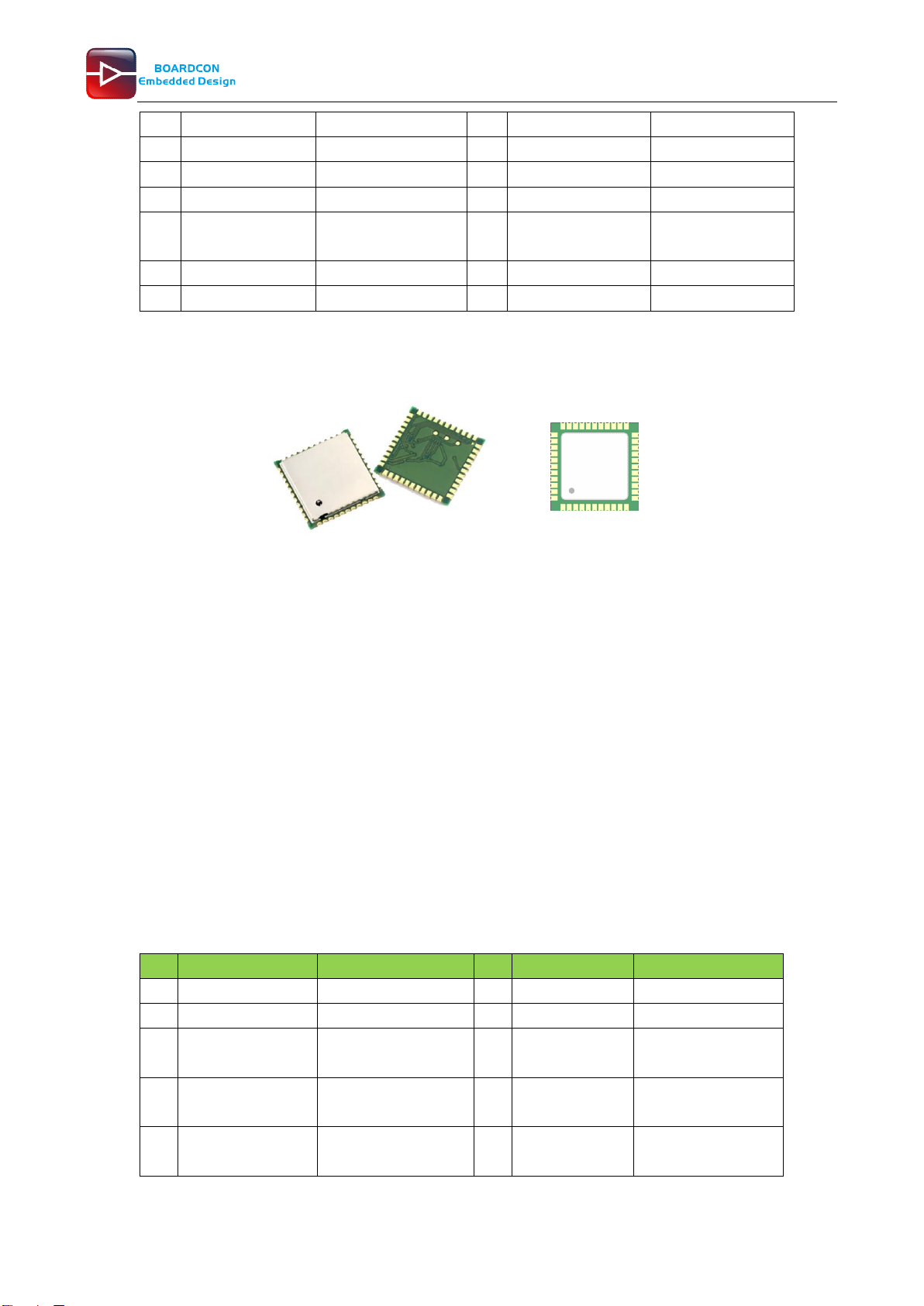
2.13 WiFi&Bluetooth (U11)
AP6236 is a low-power consumption module which has incorporated Wi-Fi and Bluetooth into one
chip. The module complies with IEEE 802.11 b/g/n standard and it could achieve up to a speed of
72.2Mbps with single stream in 802.11n draft, 54Mbps as specified in 802.11g, or 11Mbps for
802.11b to connect to the wireless LAN.
Features
⚫802.11b/g/n single-band radio
⚫Bluetooth V4.0(HS) with integrated Class 1.5 PA and Low Energy (BLE) support
⚫Concurrent Bluetooth, WLAN operation
⚫Simultaneous BT/WLAN receive with single antenna
⚫WLAN host interface options:
- SDIO v2.0 — up to 50 MHz clock rate
⚫BT host digital interface:
- UART (up to 4 Mbps)
⚫IEEE Co-existence technologies are integrated die solution
⚫ECI — enhanced coexistence support, ability to coordinate BT SCO transmissions around
WLAN receives
Pin
Signal
Description
Pin
Signal
Description
1
GND
Ground
2
WL_BT_ANT
RF I/O
3
GND
Ground
4
NC
Not connect
5
NC
Not connect
6
BT_WAKE
HOST wake-up
Bluetooth device
7
BT_HOST_WAKE
Bluetooth device to
wake-up HOST
8
NC
Not connect
9
VBAT_WL
Main power voltage
source input
10
XTAL_IN
Crystal input
Top
view
111 12
22
23
34
44
33
19
Customize the embedded system based on YourIdea
11
XTAL_OUT
Crystal output
12
WIFI_REG_ON
Internal regulators
power enable /
disable
13
WIFI_HOST_WAK
E
External Interrupt
Input / Keypad input
14
WIFI_D2
WiFi data
15
WIFI_D3
WiFi data
16
WIFI_CMD
WiFi command
17
WIFI_CLK
WiFi clock
18
WIFI_D0
WiFi data
19
WIFI_D1
WiFi data
20
GND
Ground
21
VIN_LDO_OUT
Internal Buck voltage
generation pin
22
VCCIO_WL
I/O Voltage supply
input
23
VIN_LDO
Internal Buck voltage
generation pin
24
LPO
External Low Power
Clock input
(32.768KHz)
25
NC
Not connect
26
NC
Not connect
27
NC
Not connect
28
NC
Not connect
29
NC
Not connect
30
NC
Not connect
31
GND
Ground
32
NC
Not connect
33
GND
Ground
34
BT_RST
Bluetooth reset
35
NC
Not connect
36
GND
Ground
37
NC
Not connect
38
NC
Not connect
39
NC
Not connect
40
NC
Not connect
41
UART0_CTS
Bluetooth UART
interface
42
UART0_RX
Bluetooth UART
interface
43
UART0_TX
Bluetooth UART
interface
44
UART0_RTS
Bluetooth UART
interface
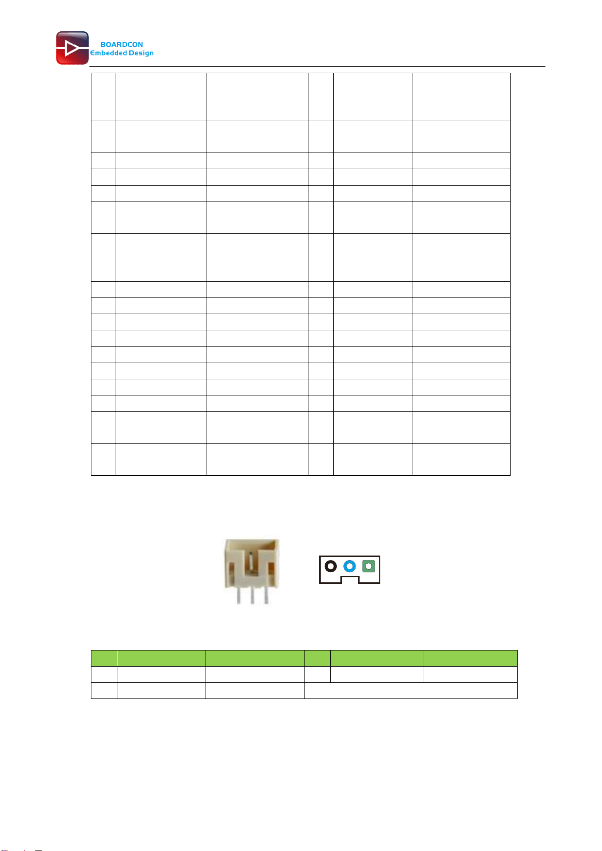
2.14 Debug UART (J10)
The debug serial port (UART2) is used to connect PC and board with the USB-to-serial cable
(CP2102).
Pin
Signal
Description
Pin
Signal
Description
1
UART2_RX
UART2 receive
2
UART2_TX
UART2 transmit
3
GND
Ground
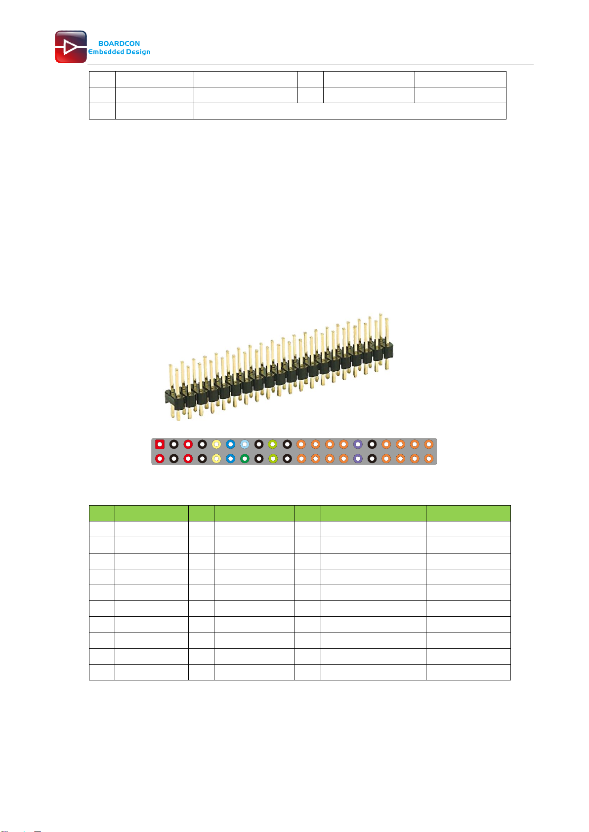
2.15 GPIO (CON4)
The GPIO is a 40-pin header connector. The pins can be defined as data input / output.
3 2 1
Other manuals for EM3288
1
Table of contents
Other Boardcon Motherboard manuals


