EVBplus Alice EduPad User manual

1
Alice EduPad for TI MSP432P401R
LaunchPad
User’s Guide
Version 1.04 06/27/2018

2
Table OF Contents
Chapter 1. Overview ...................................................................................................................................3
1.1 Welcome .................................................................................................................................3
1.2 MSP432 LaunchPad features ..............................................................................................4
1.3 Alice EduPad hardware features ........................................................................................4
Chapter 2. Software development ..........................................................................................................5
Chapter 3. Online resources ....................................................................................................................7
Chapter 4. Hardware Descriptions .........................................................................................................8
4.1 LEDs ........................................................................................................................................8
4.2 Push button switches............................................................................................................8
4.3Light sensor ...........................................................................................................................8
4.4Potentiometer ........................................................................................................................8
4.5Temperature sensor..............................................................................................................8
4.6 Speaker....................................................................................................................................8
4.7 EEPROM..................................................................................................................................8
4.8 UART communication ..........................................................................................................8
4.97-Segment LED display.........................................................................................................9
4.10 LCD display ......................................................................................................................... 10
4.11 Digital-to-Analog Converter (DAC) .................................................................................. 10
4.12H-Bridge ............................................................................................................................... 11
4.13CAN ...................................................................................................................................... 11
4.14TFT ........................................................................................................................................ 11
4.15OLED .................................................................................................................................... 12
4.16 SD card ................................................................................................................................ 12
4.17ESP8266 .............................................................................................................................. 12

3
4.18All on-board I/O headers ................................................................................................... 13
4.19 I/O pin usage ....................................................................................................................... 14
Chapter 1. Overview
1.1 Welcome
Thank you very much for purchasing our Alice EduPad trainer for TI’s MSP432 LaunchPad. The
Alice EduPad trainer is a low-cost, feature-packed universal training board for the MSP432
LaunchPad. It incorporates onboard peripherals that will make this board an ideal trainer for EE
and ECE courses in universities around the world.
For engineers, it is a convenient prototype system suitable for designers who want to rapidly
develop and prototype ARM controller applications. For students, it not only can be used as a
general trainer for freshman and sophomore but also as a versatile platform for senior projects as
well. The features of the Alice EduPad trainer create a new potential for students at every level.
Please note that the MSP432 LaunchPad and USB cable are not included with your
purchase of the Alice EduPad trainer.
The micro USB cable comes with your LaunchPad purchase from TI on line store.
https://store.ti.com/msp-exp432p401r.aspx?jktype=companionparts
Theyusuallyhave it in stock. Other distributors, like Mouser and Digi-key, all have it, but the price
may be a little higher.
The external power supply is not needed for your normal use, it’s only needed when in
standalone operation without a PC. The DCjack uses a Micro USB connector. Most of smart
phone chargers except iPhone have a 5V output with a micro USB connector, they can be used
as external power supply.
Warning:
The MSP432 LaunchPad does not have a built-in reverse-polarity-protection diode. If you
are going to experience H-Bridge with an external high voltage motor (>5V), please make
sure that the high voltage (>5V) cannot be touched with the 5V supply, or it may damage
the USB port of your laptop, or even your whole laptop.

4
1.2 MSP432 LaunchPad features:
The TI MSP432 LaunchPad isa low cost evaluation platform for ARM Cortex-M4F
microcontrollers made by TI. It has many features, the main features of the TI MSP432
LaunchPadare listed below:
•Low-power, high performance MSP432P401R MCU
48MHz 32-bit ARM Cortex M4Fwith Floating Point Unit and DSP acceleration
Power consumption: 80uA/MHz active and 660nA RTC standby operation
Analog: 24Ch 14-bit differential 1MSPS SAR ADC, Two Comparators
Digital: Advanced Encryption (AES256)Accelerator, CRC, DMA, HW MPY32
Memory: 256KB Flash, 64KB RAM
Timers: 4 x16-bit, and 2 x 32-bit
Communication: Up to 4 I2C, 8 SPI, 4 UART
•40 pin BoosterPack Connector, and support for 20 pin BoosterPacks
•Onboard XDS-110ET emulator featuring EnergyTrace+ Technology
•2 buttons and 2 LEDs for User Interaction
•RGB LED
•Back-channel UART via USB to PC
1.3 Alice EduPad hardware features:
The Alice EduPad board includes the following featuresfor teaching ARM courses:
1. Four user LEDs
2. Four pushbutton switches
3. Four Servo controls or relay outputs
4. Speaker to be driven by timer, DAC or PWM signal for alarm or music applications.
5. 7-segment display
6. 16X2 LCDwith a jumper selectable for serial or 4-bit parallel interface
7. 0.96”, 128x64 OLED header
8. 2.2” TFT QVGA display header
9. ESP8266 for WiFi applications
10. Light sensor
11. Temperature sensor
12. Potentiometer for analog input
13. 12-bit DAC
14. Dual H-Bridge for controlling two DC motors or one stepper motor
15. Two analog sensor inputs
16. MicroSD memory card slot
17. Solderless breadboard included
18. PCboard size is 6.25" X 3.1”
5
Chapter 2. Software development
It is recommended that you become familiar with the software development tools for the MSP432
LaunchPad before working with the Alice EduPad.
So the software development on the Alice EduPad is a two-step process.
1, Work on the MSP432 LaunchPad standalone and familiarize with its software development. Don’t
plug the Launchpad onto the Alice EduPad until you feel comfortable in writing a small test program
because it’s easier to test a small program on the Launchpad alone.
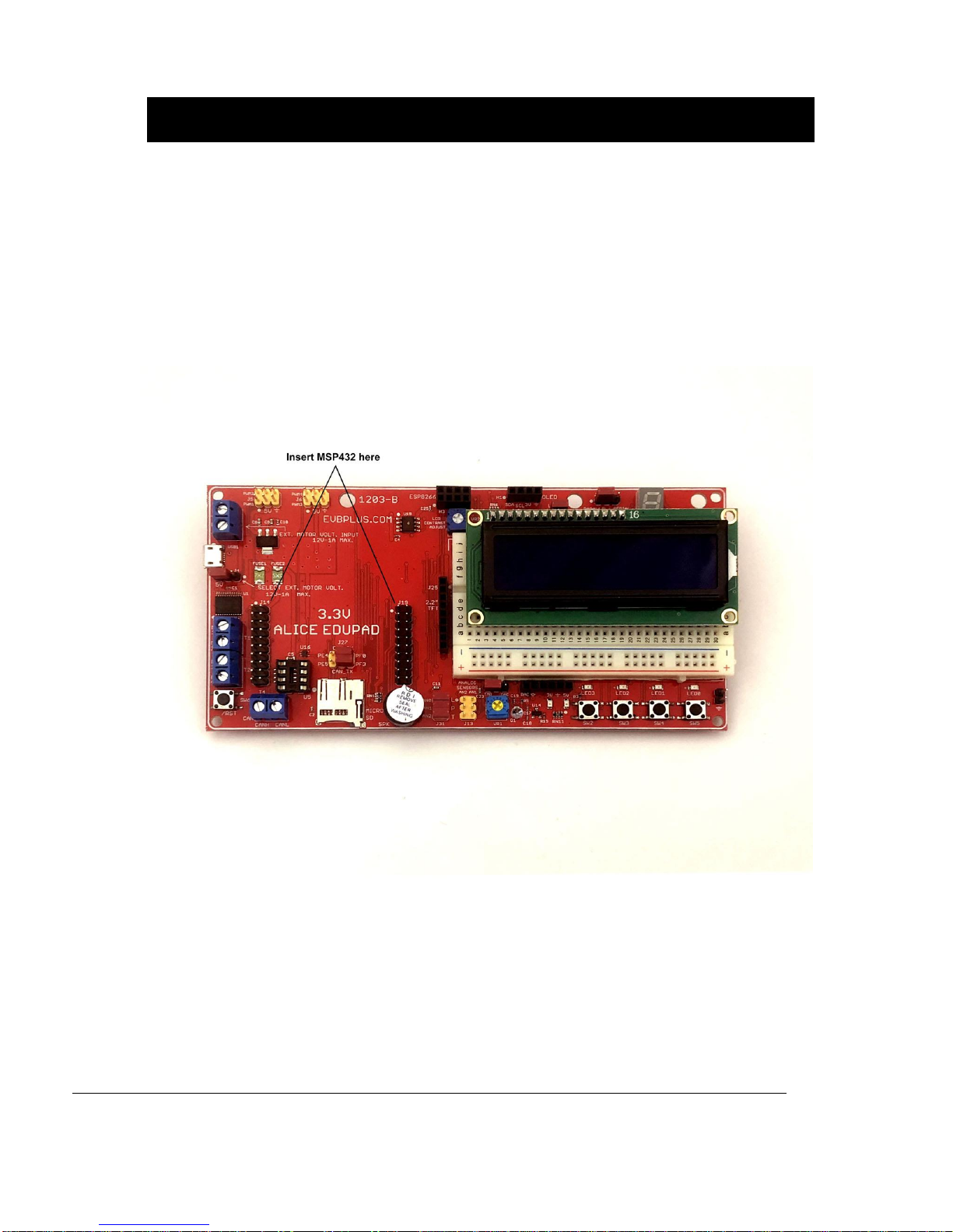
2. Insert the MSP432 LaunchPad onto the Alice EduPad’s J14 and J19.

6
The MSP432 LaunchPad on the Alice EduPad

7
TI listed three major IDE’s for LaunchPad software development:
Keil MDK-ARM
IAR Embedded Workbench
Code Composer Studio
Since Keil was acquired by ARM, for an EE or an ECE course, the Keil seems to be more popular.
Professor Mazidi and Professor Chen have chosen the Keil IDE and wrote a textbook for the MSP432
LaunchPad. Professor Mazidi is a highly regarded author of many textbooks for embedded systems,
and Professor Chen is an ARM controller software expert who wrote and tested all C and Energia
sample programs for the Alice EduBase and the Alice EduPad. We are very grateful fortheir hard work.
You can purchase their books at Amazon.
https://www.amazon.com/MSP432-Programming-Embedded-Systems-
books/dp/0997925914/ref=sr_1_2?s=books&ie=UTF8&qid=1474025605&sr=1-
2&keywords=MSP432+ARM+Book+Mazidi+and+Naimi
Sample programs are available at Professor Mazidi’s web site:
http://www.MicroDigitalEd.com/ARM/MSP432_books.htm
Chapter 3. On-line resources
MSP432 LaunchPad user’s guide including schematic:
http://www.ti.com/lit/ug/slau597f/slau597f.pdf
How to download and install Keil and How to Create a C Project in Keil and sample programs:
http://www.MicroDigitalEd.com/ARM/TI_ARM_books.htm
This book can be used with Alice EduPad.
If you have any technical questions regarding the MSP432 LaunchPad, you can post a message at
the MSP432 forum. ManyTI engineers are active on the forum to answer yourquestions.
If you have any question regarding the Alice EduPad hardware and need a tech support call us at 1-
847 250-5160 or email your question to evbplus @ gmail.com

8
Chapter 4: Hardware Descriptions
The circuit is designed in such waythat the value of all resistorsand capacitors are not critical.
4.1 LEDs:
The P3.2, P3.3, P2.5, P2.4 are connected to the LED0-LED3 via a buffer (U8). In order to turn
on an LED, you need to program the corresponding pin as output and set it high.
4.2 Push button switches:
The P4.4, P4.2, P4.0, P6.1 are connected to the 4 push buttons, SW2-SW5.
4.3 Light sensor (AN0)
The light sensor (a TEMP4452 or equivalent) is connected to the PE1 (AIN2) of the ADC port.
4.4 Potentiometer (AN1)
The 5K potentiometer VR2 is connected to the PE2 (AIN1) of the ADC port
4.5 Temperature sensor (AN2)
The temperature sensor(LM45 orequivalent) is connected to the PE5 (AIN8) of the ADC port
4.6 Speaker
The speaker is a 5V audio magnetic transducer and it’s driven by the PC4, a timer, or by the
DAC output from U17 (MCP4725). The signal source of the speaker is selected by the jumper
J24.
4.7 Serial I2C EEPROM
A small serial EEPROM (24LC02) is provided for experimenting with I2C communication.
4.8 UART communication
When P3.2 and P3.3 are not used for the Lab assignment #1 (see above paragraph #4.1 and
#4.2) ornot used for driving the onboard H-Bridge, theycan be used asa UART.
The UART can be used by user’s application programs. It supports direct 3.3V digital signal
interface with other boards, or use a 3V USB serial adapter (a FTDI cable) for interfacing with a
PC.
9
4.9 7-Segment LED display
The type of the 7-segment LED display on the Alice EduPad is called common anode, all
cathodes are driven individually by an outputpin and the anode is connected to the 5V supply.
Before sending a number to a 7-segment LED display, the number must be converted to its
corresponding 7-segment code depending on how the 7-segment display is connected to an
output port.
Because there are not enough I/O pins available, the Alice EduPad incorporates an HCT595
shift register to drive the cathodes. When a cathode is low, the corresponding LED segment
lights up.
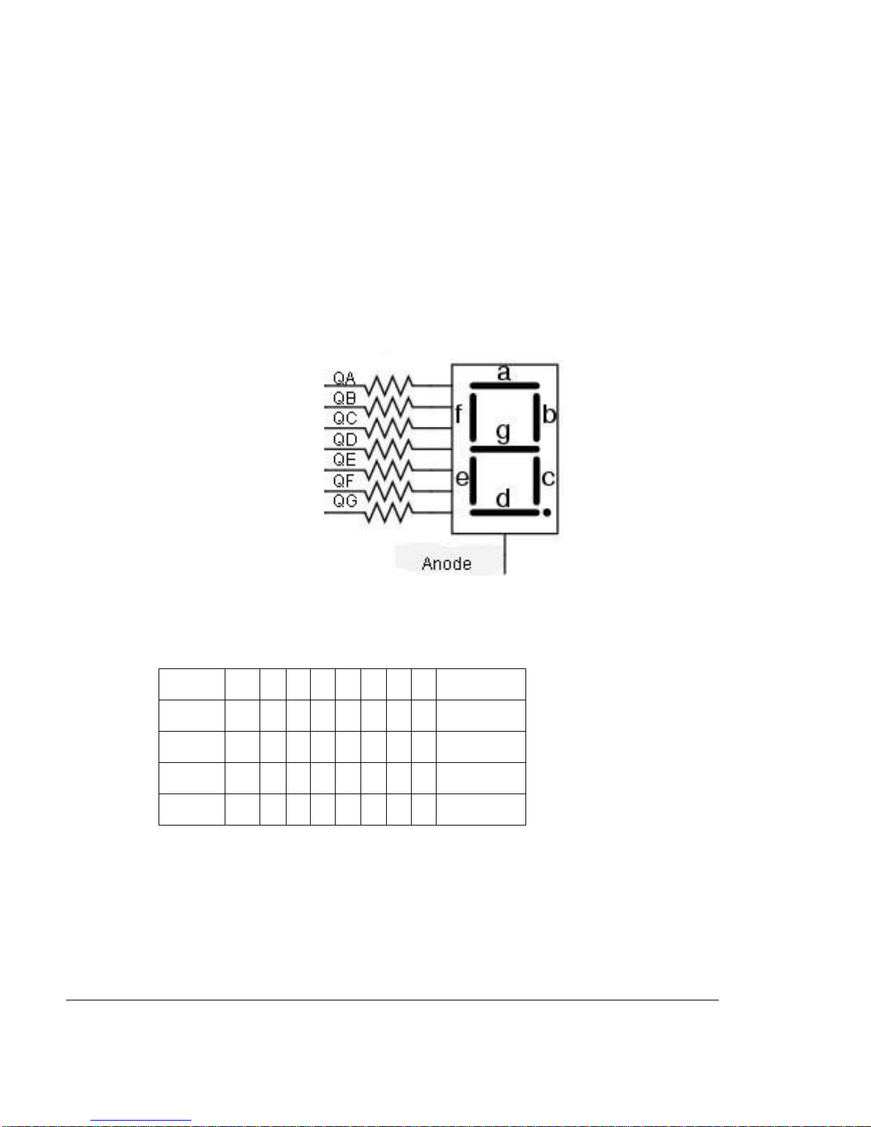
By convention, the 7segments are called segment A, B, C, D, E, F and G. Their locations in the
display are shown below:
The segment A, B, C, D, E, F, G and DecimalPointare driven byQA, QB, QC, QD, QE, QF,
QG, and QH, respectively. The hex value of the segment code is shown in the following table:
Number
DP
G
F
E
D
C
B
A
Hex Value
1
0
0
0
0
0
1
1
0
0x06
2
0
1
0
1
1
0
1
1
0x5B
3
0
1
0
0
1
1
1
1
0x4F
4
0
1
1
0
0
1
1
0
0x66
The above table only lists #1 to #4, it’s not difficult to figure out the other numbers once
you know how #1 to #4 are created. To display the number 1 on the 7-segment display,
you normally send 0x06 to the HCT595. Since this has a common anode, you need to
invert the 0x06 before sending data out to the HCT595. You could invert the number and
send 0xF9 to the HCT595 or you could use the C operator and send ~0x06.

10
4.10 LCD display
4.10.1. Serial interface LCD: (the jumper is placed on the 2 right-hand pins of J23)
The Alice EduPad incorporates an HCT595 shift register (U6) to control the LCD display. The
chip select for the HCT595 is P6.7 of the MSP432 LaunchPad.
The U6 outputs QA-QH as the control and data bits D0-D1, D4-D7 for the LCD.
The pinouts of J1 are as follows:
Pin 1 GND
Pin 2 VCC (5V)
Pin 3 Connect to GNDvia the VR1 for contrast adjustment
Pin 4 QA (D0) RS pin for LCD module
Pin 5 GND Write only for LCD module
Pin 6 QB (D1) EN pin for LCD module
Pin 7 Not used
Pin 8 Not used
Pin 9 Not used
Pin 10 Mot used
Pin 11 QE (D4) DB4 pin for LCD module
Pin 12 QF (D5) DB5 pin for LCD module
Pin 13 QG (D6) DB6 pin for LCD module
Pin 14 GH (D7) DB7 pin for LCD module
Pin 15 Via a 100 Ohm resistor to VCC LED backlight for LCD module
Pin 16 Backlight ground EN/DIS for LED back light
The HCT595 is connected to theLCD controller with QE ~ QHto DB4 ~ DB7,
QA to RS, QB to enable. The QC and QD are not used.
The LCD module is hardwired for write-only operation.
4.10.2. Parallel interface LCD: (the jumper is placed on the 2 left-hand pins of J23)
The Alice EduPad also incorporates a parallel interface for the LCD, the P3.6, P5.2, P5.0 and
P4.6 are connected to the D4-D7 of the LCD via a 74HCT245 buffer (U18). The control pins are
P3.0 for LCD R/S and P6.7 for LCD EN.
4.11 Digital-to-Analog Converters (DAC)
The MCP4725, a 12-bit I2C DAC is installed for learning I2C communication.
It converts a digital binary code to an analog signal so a program can generate different
waveforms from the DAC.
The DAC’s analog output is provided on the J32, labeled as DAC. One way of testing the DAC
driver is to connect the DAC output to an ADC input, so a user can send a binary code to the
DAC and read the code back from the ADC.

11
4.12 H-Bridge
The H-bridge driver TB6612FNG is similarto the SN754410N, but has MOSFET output. It’s much
more efficient than the SN754410N, especially for controlling low voltage motors. The control
software is the same for both IC’s. It can control two DC motors or one stepper motor.
It takes two pins, P3.2 and P3.3, to control motor direction, one must be set at high, and the other
one must be set at low. If P3.2 is high and P3.3 is low the motor will turn clockwise, then if P3.2 is
low and P3.3 is high the motorwill turn count clockwise. If both P3.2 and P3.3 are set at the
same state, the motor stops.
A DC motor is connected to the terminals labeled with M1 and M2, If the motoris turned in the
opposite direction from what you expect, just swap the motor connections on the M1 and M2, you
don’t need to change your software.
The motors to be used to test your software should be small, low current and low voltage DC
motors, like under12V and 300mA.
The third pin is the PWM input for receiving different pulse widths to varymotor speed. It isdriven
bypin P2.7 of the Launchpad. The sample program is available on Professor Mazidi’s web site.
The other half of the H-bridge driver is controlled by P2.5, P2.4 for direction and P2.6 for PWM.
The outputs are M3 and M4.
Combining M1, M2, M3, and M4, the H-bridge driver can be used to drive a bipolar or unipolar
stepper motor.
4.13 CAN
CAN interface is provided, but the CAN transceiver is not installed. If you are interested in CAN
programming, place a MCP2551 into the 8-pin DIP socket. The J27 selects one of CAN ports,
PE4 and PE5, or PF0 and PF3. Two jumperson the J27 must beplaced HORIZONTALLY.
4.14 TFT
J25 is for a common 2.2” TFT QVGA display with SPI interface. Thepinoutsare listed below:
Pin1
5V
Pin2
Ground
Pin3
Chip select
P6.7
Pin4
Reset
Pin5
R/S
P3.0
Pin6
MOSI
P1.6
Pin7
SCLK
P1.5
Pin8
Backlight
Pin9
MISO
P1.7

12
4.15 OLED
H1 is used foran OLED with I2C interface. The connections are:
Pin1 SDA (P6.4)
Pin2 SCL (P6.5)
Pin3 3.3V
Pin4 Ground
4.16 SD-Card
The SD-Card slot uses SPI interface. The pinouts are listed below:
4.17 ESP8266 (ESP-01 module)
The purpose of including the ESP8266 is to bring WiFi capability into students’ projects.
The ESP8266 is controlled by the MSP432 LaunchPad via AT commands in serial
communication.
Many sample programs are downloadable from Professor Mazidi’s web site
Chip select
P6.6
MOSI
P1.6
SCLK
P1.5
MISO
P1.7
Pin Name
Connect to
Pin Name
Connect to
1
TX
RX (LED0) of LP
2
GND
GND of LP
3
CH_PD
3.3V
4
GPIO2
Pull up via a 10K
5
RST
/Reset of LP
6
GPIO0
Open (internal pull up)
7
VCC
3.3V
8
RX
TX (LED1) of LP

13
http://www.MicroDigitalEd.com/ARM/MSP432_books.htm
4.18 All on-board headers:
J1 LCD connector for a 16x2 LCD
J4 DCmotor power source select, jumperon left side foronboard 5V, on right for
external power voltage, <12V, <1A.
J5 Two servo outputs, controlled by P2.7 and P2.6. Servos are supplied with 5V
J6 Two servo outputs, controlled by P2.5 and P5.5. Servos are supplied with 5V
J11 LCD backlight
J13 Analog sensor inputs and can be used for an IR distance sensor, such as GP2D12
or other analog or digital sensors
J14 LaunchPad main pin header 1
J19 LaunchPad main pin header 2
J23 LCD interface type select, serial or parallel
J24 Speaker source select, Timer or DAC
J25 2.2” QVGA TFT display interface
J27 CAN1/CAN2 select (not needed for MSP432 LaunchPad)
J31 Light, potentiometer and temperature enable jumpers
J34 FTDI connector
H1 0.96” OLED
H3 ESP8266

14
4.19 I/O pin usage
Pin Name
Header Pins
I/O device(s)
P4.5
J14-14, J31-1
AN0, Light sensor
P4.7
J14-16, J31-3
AN1, Potentiometer
P4.3
J14-11, J31-5
AN2, Temperature sensor
P2.7
J19-1, J1-1
PWM1 for servo
P2.6
J19-3, J1-2
PWM2 for servo
P2.5
J19-8, J4-1
PWM3 for servo
P5.5
J14-20, J4-2
PWM4 for servo
P5.6
J19-7, J24-1
Speaker
P6.6
J19-9
SD memory
P6.7
J19-11, J25-3
LCD 16x2, TFT
P2.3
J19-13
7-segment display
P3.0
J19-6
TFT’s D/C, LCD’s R/S
P3.2
J14-5, J34-3
LED0, H-Bridge, ESP8266
P3.3
J14-7, J34-2
LED1, H-Bridge, ESP8266
P2.5
J19-4
LED2, H-Bridge
P2.4
J19-5
LED3, H-Bridge
P6.1
J14-6
SW5, Pushbutton
P4.0
J14-8
SW4, Pushbutton
P4.2
J14-10
SW3, Pushbutton
P4.4
J14-12
SW2, Pushbutton
P1.5 (SPI-SCLK)
J14-13
7-segment display, LCD, TFT
P1.7 (SPI-MISO)
J19-14
7-segment display, LCD, TFT
P1.6 (SPI-MOSI)
J19-12
7-segment display, LCD, TFT
P6.5 (I2C-SCL)
J14-17
EEPROM, OLED
P6.47 (I2C-SDA)
J14-19
EEPROM, OLED

15
Table of contents
Popular Motherboard manuals by other brands


Asus
Asus P5G41T-M LX2 user manual

Infineon Technologies
Infineon Technologies Cypress S6SAP413A00SA1001 Operation guide

IWILL
IWILL DVD266u-RN manual

ASROCK
ASROCK 890GX Extreme3 Specifications

NXP Semiconductors
NXP Semiconductors S32K116 EVB quick start guide

Honeywell
Honeywell Gamewell FCI ILI-MB-E3 Product installation document