Boardcon EM3288 User manual


www. boardcon.com
1
1. Introduction
1.1. About this Manual
This manual is intended to provide the user with an overview of the board and benefits, complete features
specifications, and set up procedures. It contains important safety information as well.
1.2. Feedback and Update to this Manual
To help our customers make the most of our products, we are continually making additional and updated
resources available on the Boardcon website (www.boardcon.com ,www.armdesigner.com).
These include manuals, application notes, programming examples, and updated software and hardware.
Check in periodically to see what’s new!
When we are prioritizing work on these updated resources, feedback from customers is the number one
influence, If you have questions, comments, or concerns about your product or project, please no
hesitate to contact us at support@armdesigner.com.
1.3. Limited Warranty
Boardcon warrants this product to be free of defects in material and workmanship for a period of one year
from date of buy. During this warranty period Boardcon will repair or replace the defective unit in
accordance with the following process:
A copy of the original invoice must be included when returning the defective unit to Boardcon. This limited
warranty does not cover damages resulting from lighting or other power surges, misuse, abuse,
abnormal conditions of operation, or attempts to alter or modify the function of the product.
This warranty is limited to the repair or replacement of the defective unit .In no event shall Boardcon be
liable or responsible for any loss or damages, including but not limited to any lost profits, incidental or
consequential damages, loss of business, or anticipatory profits arising from the use or inability to use
this products.
Repairs make after the expiration of the warranty period are subject to a repair charge and the cost of
return shipping. Please contact Boardcon to arrange for any repair service and to obtain repair charge
information.

www. boardcon.com
2
Content
1 EM3288 Introduction..............................................................................................................................................3
1.1 Summary...................................................................................................................................................... 3
1.2 Rockchip RK3288 Features...................................................................................................................... 3
1.3 EM3288 Specifications...............................................................................................................................5
1.4 PCB Dimension........................................................................................................................................... 6
1.5 Block Diagram............................................................................................................................................. 6
1.6 Motherboard Power meter.........................................................................................................................7
1.7 CPU Introduction......................................................................................................................................... 7
2 Peripherals Introduction...................................................................................................................................... 11
2.1 Power (P6, J17).........................................................................................................................................11
2.2 Ethernet (JP1)........................................................................................................................................... 12
2.3 USB HOST (P2, P3)................................................................................................................................. 13
2.4 USB OTG (J8)........................................................................................................................................... 14
2.5 SD (J1)........................................................................................................................................................14
2.6 HDMI (PH1)............................................................................................................................................... 15
2.7 Audio I/O (J6, J7, MIC1).......................................................................................................................... 16
2.8 VGA (J20)...................................................................................................................................................17
2.9 LVDS (CON3)............................................................................................................................................ 17
2.10 TTL LCD (J21).........................................................................................................................................18
2.11 MIPI (CON5)............................................................................................................................................ 19
2.12 GPS(MU4)............................................................................................................................................... 19
2.13 WiFi&Bluetooth(U11)..............................................................................................................................20
2.14 Debug serial port (J10).......................................................................................................................... 22
2.15 GPIO (CON4).......................................................................................................................................... 22
2.15 Control (J2).............................................................................................................................................. 23
2.16 Buttons (K1, K2)......................................................................................................................................24
2.17 3G connector & SIM slot (CON2, P4)..................................................................................................24
2.18 SATA & SATA_Power (J14, J18).......................................................................................................... 26
2.19 RTC (BT1)................................................................................................................................................26
3 Product Configurations........................................................................................................................................27
3.1 Standard Contents....................................................................................................................................27
3.2 Optional Parts............................................................................................................................................27

www. boardcon.com
3
1 EM3288 Introduction
1.1 Summary
EM3288 is a single board computer based on the Rockchip RK3288, Quad Core Cortex-A17 @1.8GHz.
RK3288 is powerful on multithreaded computing operation, graphics processing and video decoding
ability. RK3288 supports Mali-T760 MP4 Graphics Processing, OpenGL ES1.1/2.0/3.0, OpenVG1.1,
OpenCL, Directx11, and can 4Kx2K archieve 4kx2k H.264 and 10 bits of H.265 video decoding, 500%
performance boost over Mali-400. On display aspects, RK3288 supports up to 18Gbps Data transmission
rate and 4Kx2K@60Hz Video resolution.
It is implemented with a MINI3288 computer-on-module providing most of the functions and interfaces,
and EM3288_C carrier board providing connectors and several additional functions. The rich feature set
of EM3288 is customizable according to the price / performance needs of the target application. EM3288
contains expansion connectors which accommodate a wide range of standard peripheral devices. Wide
input range switched power supply is compatible with requirements for telecom and automotive
applications. EM3288 is provided with full ready-to-run Android4.4.4 and Ubuntu SW packages and
comprehensive user manual and designing guide.
1.2 Rockchip RK3288 Features
The first SoC with real 4Kx2K video decoder
The first SoC with total solution for HDCP2.x security.
RK3288 is a high performance application processor for high-end tablet, notebook, all-in-one device,
smart monitor and TV-Box. Especially it is one of most powerful solution for 4Kx2K TV-Box.
Integrate quad-core Cortex-A17 with separately Neon and FPU coprocessor, also shared 1MB L2 Cache.
More than 32bits address will support up to 8GB access space.
Currently, latest generation and most powerful GPU is embedded to support smoothly high-resolution
(3840x2160) display and mainstream game. Support OpenVG1.1, OpenGL ES1.1/2.0/3.0, OpenCL1.1,
RenderScript and DirectX11 etc.
Full-format video decoder, including 4Kx2K multi-format decoder.
Lots of high-performance interface to get very flexible solution, such as multi-pipe display with
dual-channel LVDS, dual-channel MIPI-DSI, eDP1.1, HDMI2.0 , dual-channel MIPI-CSI2 interface with
13MP ISP embedded.
Fully-integrated hardware-based security solution will provide HDCP2.x for miracast and all kinds of DRM
solution based on different OS.
Dual-Channel 64bits DDR3/LPDDR2/LPDDR3 provide demanding memory bandwidths for
high-performance and high-resolution application.
CPU

www. boardcon.com
4
Quad-Core Cortex-A17
Separately Integrated Neon and FPU per CPU
32KB/32KB L1 ICache/DCache per CPU
Unified 1MB L2 Cache
LPAE (Large Physical Address Extensions) , support up to 8GB address
Space Virtualization Extensions Support
DVFS support
GPU
- 3D GPU
Quad-Core Mali-T7 series, latest powerful graphics processor
Architected for GPU computing
Support OpenGL ES1.1/2.0/3.0, OpenVG1.1, OpenCL1.1 and Renderscript, Directx11
DVFS support
- 2D GPU
Multi-Core architecture
Up to 8Kx8K input and 4Kx4K
Output High-quality image scale
Up/down Dither operation
Image rotation with 90/180/270 degree or x/y-
mirror BitBLT, Alpha Blending, Raster Operation
VPU
- Video Decoder
Support MPEG-2,MPEG-4,AVS,VC-1,VP8,MVC with up to 1080p@60fps
Support multi-format video decoder with up to 4Kx2K
High-quality deinterleave
- Video Encoder
Support muti-format video encoder with up to 1080p@30fps
- Video Input
Dual-channel input for front and rear camera
Dual-channel MIPI-CSI2 interface with 4-lane per channel
8/10/12 bits standard DVP interface
Maximum 5Mpixel for front camera
Maximum 13Mpixel for rear camera with high-performance ISP
- Video Display
Dual-panel display with 2 separately interface
Maximum resolution is 4Kx2K
CABC support to decrease interface power

www. boardcon.com
5
Dual channel 8/10bits LVDS
Dual channel MIPI-DSI
HDMI2.0 to support maximum 4Kx2K display
Optional eDP1.1 interface
1.3 EM3288 Specifications
Feature
Specifications
CPU
· Rockchip RK3288 , Quad Core Cortex-A17 up to 1.8GHz
· 28nm HKMG process
GPU
· ARM Mali-T764 GPU, with TE, ASTC, AFBC technology
· Support OpenGL ES1.1/2.0/3.0, OpenVG1.1, OpenCL, DirectX11
Memory
2GB DDR3
Flash
8GB eMMC Flash, up to 32GB
Power
5V/3A
USB
3x USB2.0 Host, 1x USB2.0 OTG
LCD
1x 26-pin MIPI connector, 1x 40-pin LVDS(1280x800), 1x 40-pin TTL LCD
connector
VGA
1x VGA connector
Ethernet
10/100/1000M, RJ45 interface
Serial port
1x 3pin connector, for debug
HDMI
HDMI V2.0, up to 4Kx2K@60fps
Audio
Microphone Header, MIC
WiFi/Bluetooth
AP6210 module. Support WiFi and Bluetooth. 2.4GHz/5GHz WiFi, support
802.11 a/b/g/n; BT4.0
SD card
1x Micro SD card slot
RTC
Real Time Clock, powered by external lithium battery
Button
Power, Recover
GPIO
1x 8-pin Control;
1x 40-pin GPIO
Other interfaces
1x SATA, 1x SATA-Power, 1x 3G Module, 1x SIM Card, 1x Lithium battery
interface
Optional modules
GPS, WIFI, 3G, Bluetooth, USB camera
Dimension
117.5 x 175.3mm

www. boardcon.com
6
1.4 PCB Dimension
1.5 Block Diagram

www. boardcon.com
7
1.6 Motherboard Power meter
Support
voltage
5v/2.5A
System
Connected devices
Electric
current(A)
System
Connected devices
Electric
current(A)
Android
4.4.4
5v power
0.464
Android
4.4.4
Power, 10.1 inch HD
capacitive screen
0.753
Android
4.4.4
Power, sd card, play
1080P video, U disk, usb
Mouse, debug serial,
Ethernet, 10.1 inch HD
capacitive LVDS,
headphone
1.13
Android4
.4.4
SLEEP+(Power, sd
card, U disk, usb
Mouse, debug
serial, Ethernet,
10.1 inch HD
capacitive LVDS,
headphone )
0.35
1.7 CPU Introduction
MINI3288 is a Computer-on-module (CoM) based on Rockchip RK3288 SoC. Integrate quad-core
Cortex-A17 with separately Neon and FPU coprocessor, also shared 1MB L2 Cache. Support real 4Kx2K
video decoder, 3D GPU processor with OpenGL ES3.0, OpenCL1.1 and DirectX11. It is a high
performance application module for high-end tablet, notebook, all-in-one device, smart monitor and
TV-Box.
Board Dimension
* Board size: 70mm x 58mm
* Pin to Pin space: 1.3mm
* Pin number: (J11+J12) x 100 = 200 pins
* Layer: 8 Layers, complying with EMS/EMI

www. boardcon.com
8
Feature
* MINI3288 Development Board: EM3288
* Processor: Rockchip RK3288, Quad Core Cortex-A17 @ 1.8GHz
* DDR: 2GB DDR3
* NAND Flash: 8GB eMMC
* Preinstalled Android4.4.4
* Power supply: 5V/2.5A
* The modular is led out most signals of RK3288, such as USB Host, USB OTG, LCD, VGA, UART,
Gigabit Ethernet, HDMI, Audio, SD/MMC/SDIO, SPI, I2C, I2S, ADC, MIPI-CSI/DSI, LVDS and so on.
* Application: MID, POS, PND, and Terminal controller
* Compatible module: MINI3066,MINI4418
PCB Dimension
Pin Definition
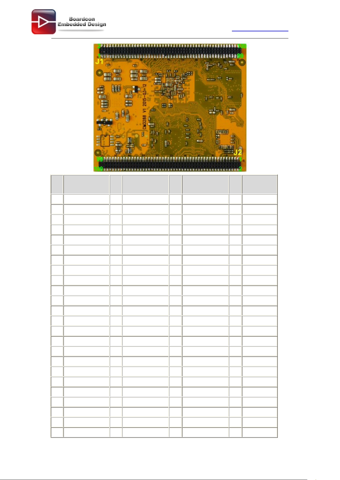
www. boardcon.com
9
Pin
(J1)
Signal
Pin
(J1)
Signal
Pin
(J2)
Signal
Pin
(J2)
Signal
1
TX_C
51
MIPI_TX/RX_D2P
1
VDD5V
51
TS0_D7
2
TX_0-
52
MIPI_TX/RX_D1P
2
GND
52
TS0_D6
3
TX_C+
53
MIPI_TX/RX_D3P
3
VDD5V
53
GND
4
TX_0+
54
GND
4
GND
54
TS0_SYNC
5
GND
55
MIPI_TX/RX_D3N
5
nRESET
55
TS0_D2
6
GND
56
VDD3V3_EN
6
MDI0+
56
TS0_D3
7
TX_1-
57
HSIC_STROBE
7
MDI1+
57
TS0_D0
8
TX_2-
58
HSIC_DATA
8
MDI0-
58
TS0_D1
9
TX_1+
59
GND
9
MDI1-
59
TS0_CLK
10
TX_2+
60
CIF_D1
10
LCD1_BL
60
TS0_VALID
11
HDMI_HPD
61
CIF_D0
11
MDI2+
61
TS0_ERR
12
HDMI_CEC
62
CIF_D3
12
MDI3+
62
DEMO_RST
13
I2C5_SDA_HDMI
63
CIF_D2
13
MDI2-
63
SDMMC_CLK
14
I2C5_SCL_HDMI
64
CIF_D5
14
MDI3-
64
GND
15
GND
65
CIF_D4
15
GND
65
SDMMC_D0
16
LCD_VSYNC
66
CIF_D7
16
RST_KEY
66
SDMMC_CMD
17
LCD_HSYNC
67
CIF_D6
17
SDIO0_CMD
67
SDMMC_D2
18
LCD_CLK
68
CIF_D9
18
SDIO0_D0
68
SDMMC_D1
19
LCD_DEN
69
CIF_D8
19
SDIO0_D1
69
SDMMC_DET
20
LCD_D0_LD0P
70
VIN_INT
20
SDIO0_D2
70
SDMMC_D3
21
LCD_D1_LD0N
71
VIN_EN
21
SDIO0_D3
71
SDMMC_PWR
22
LCD_D2_LD1P
72
CIF_HREF
22
SDIO0_CLK
72
PWR_LED
23
LCD_D3_LD1N
73
CIF_VSYNC
23
BT_WAKE
73
GND
24
LCD_D4_LD2P
74
CIF_CLKOUT
24
NFC_WAKE
74
SATA_EN

www. boardcon.com
10
25
LCD_D5_LD2N
75
CIF_CLKIN
25
WIFI_REG_ON
75
I2S_SDI
26
LCD_D6_LD3P
76
I2C3_SCL
26
BT_HOST_WAKE
76
I2S_MCLK
27
LCD_D7_LD3N
77
I2C3_SDA
27
WIFI_HOST_WAKE
77
I2S_SCLK
28
LCD_D8_LD4P
78
GND
28
BT_RST
78
I2S_LRCK_RX
29
LCD_D9_LD4N
79
NFC_HOST_WAKE
29
WORK_LED
79
I2S_LRCK_TX
30
LCD_D10_LCK0P
80
3G_PWEN
30
SATA_RST
80
I2S_SDO0
31
LCD_D11_LCK0N
81
TOUCH_RST
31
LCD1_BL_EN
81
2S_SDO1
32
LCD_D12_LD5P
82
IR_IN
32
TOUCH_INT
82
I2S_SDO2
33
LCD_D13_LD5N
83
LED0_AD0
33
OTG_VBUS_DRV
83
I2S_SDO3
34
LCD_D14_LD6P
84
LED1_AD1
34
NFC_REG_ON
84
SPDIF_TX
35
LCD_D15_LD6N
85
VCC_LAN
35
UART0_RX
85
I2C2_SDA
36
LCD_D16_LD7P
86
PS2_DATA
36
UART0_TX
86
GND
37
LCD_D17_LD7N
87
PS2_CLK
37
GND
87
I2C1_SDA
38
LCD_D18_LD8P
88
ADC0_IN
38
UART0_CTS
88
I2C2_SCL
39
LCD_D19_LD8N
89
HUB_RST
39
OTG_DM
89
I2C4_SDA
40
LCD_D20_LD9P
90
KEY_IN
40
UART0_RTS
90
I2C1_SCL
41
LCD_D21_LD9N
91
VCCIO_SD
41
OTG_DP
91
UART2_RX
42
LCD_D22_LCK1P
92
ADC2_IN
42
OTG_ID
92
I2C4_SCL
43
LCD_D23_LCK1N
93
VCCA_18
43
HOST1_DM
93
UART3_RX
44
GND
94
VCCA_33
44
OTG_DET
94
UART2_TX
45
MIPI_TX/RX_CLKN
95
VCC_18
45
HOST1_DP
95
UART3_RTSn
46
MIPI_TX/RX_D0P
96
VCC_RTC
46
HOST2_DM
96
UART3_TX
47
MIPI_TX/RX_CLKP
97
VCC_IO
47
TS0_D5
97
LCD2_BL
48
MIPI_TX/RX_D0N
98
GND
48
HOST2_DP
98
UART3_CTSn
49
MIPI_TX/RX_D2N
99
VCC_IO
49
TS0_D4
99
PWR_KEY
50
MIPI_TX/RX_D1N
100
GND
50
GND
100
DEMO_INT

www. boardcon.com
11
2 Peripherals Introduction
2.1 Power (P6, J17)
EM3288 Power Supply – 5V DC power supply or external Li+ battery
5V/2.5A DC power supply (P6)
Pin
Signal
Description
Pin
Signal
Description
1
VDD5V
Main power supply. DC 5V power in
2
GND
Ground
3
GND
Ground
Lithium battery (J17)
EM3288 gains a Li+ battery management unit and provides an external Li+ battery interface.
(Reserved interface, the function is not supported currently.)

www. boardcon.com
12
Pin
Signal
Description
Pin
Signal
Description
1
VBAT
Li+ Battery
2
GND
Ground
2.2 Ethernet (JP1)
RK3288 has integrated Gigabit Ethernet MAC. EM3288 adopts RTL8211E as the Ethernet chip. RJ45
connector
Feature
* Supports 10/100/1000-Mbps data transfer rates with the RGMII interfaces
* Supports both full-duplex and half-duplex operation
* Supports IEEE 802.1Q VLAN tag detection for reception frames
Pin
Signal
Description
Pin
Signal
Description
1
COM
Common
2
MDI0+
Bi-directional
transmit/receive pair 0
3
MDI0-
Bi-directional
transmit/receive pair 0
4
MDI1+
Bi-directional
transmit/receive pair 1
5
MDI2+
Bi-directional
transmit/receive pair2
6
MDI2-
Bi-directional
transmit/receive pair2
7
MDI1-
Bi-directional
transmit/receive pair 1
8
MDI3+
Bi-directional
transmit/receive pair 3
9
MDI3-
Bi-directional
transmit/receive pair 3
10
GND
Ground
11
VDD_LAN
3.3.V
12
LINK
Detect link
13
GND
Ground
14
SPEED
Detect speed
15
GND
Ground
16
GND
Ground

www. boardcon.com
13
2.3 USB HOST (P2, P3)
EM3288 provides 3x USB2.0 Host. One is a single USB (P2), and the other is a double-USB (P3). The
3-ch USB HOST interfaces are extended by AU6256 which is a fully compliant with the USB 2.0 hub
specification and is designed to work with USB host as a high-speed hub. It is used to connect USB
mouse, U disk, USB camera, and other USB devices, supports hot-plug.
Feature
* Compatible with USB Host2.0 specification
* Supports high-speed (480Mbps), full-speed (12Mbps) and low-speed (1.5Mbps) mode
* Supports automatic switching between bus- and self-powered modes
* Provides 16 host mode channels
* Support periodic out channel in host mode
Single-Host (P2)
Pin
Signal
Description
Pin
Signal
Description
1
VCC_USB
USB Power. DC 5V
2
USB_DM2
USB data-
3
USB_DP2
USB Data+
4
GND
Ground
5
GND
Ground
6
GND
Ground
7
GND
Ground
Double- Host (P3)
Pin
Signal
Description
Pin
Signal
Description
1
VCC_USB
USB Power. DC 5V
2
USB_DM4
USB data-
3
USB_DP4
USB Data+
4
GND
Ground
5
VCC_USB
USB Power. DC 5V
6
USB_DM3
USB data-

www. boardcon.com
14
7
USB_DP3
USB Data+
8
GND
Ground
9
GND
Ground
10
GND
Ground
11
GND
Ground
12
GND
Ground
2.4 USB OTG (J8)
EM3288 OTG is a Micro USB2.0 port, it is used to download image and ADB transfer file.
Feature
* Compatible with USB OTG2.0 specification
*Supports USB 2.0 High Speed (480Mbps), Full Speed (12Mbps) and Low Speed (1.5Mbps) operation in
host mode
*Supports USB 2.0 High Speed (480 Mbps) and Full Speed (12 Mbps) operation in peripheral mode.
*Hardware support for OTG signaling, session request protocol, and host negotiation protocol.
Micro USB
Pin
Signal
Description
Pin
Signal
Description
1
OTG_DET
OTG detection. OTG
5V power supply
2
OTG_DM
OTG data -
3
OTG_DP
OTG data+
4
OTG_ID
OTG ID indicator
5
GND
Ground
6
GND
Ground
7
GND
Ground
2.5 Micro SD (J1)
The Micro SD card is used as an external storage device. The MMC controller interface supports up to
4-bit transfer modes. MMC is always accessible through the carrier board interface. It does not support
hot-plug.

www. boardcon.com
15
Pin
Signal
Description
Pin
Signal
Description
1
SDMMC_D2
SD/MMC data2
2
SDMMC_D3
SD/MMC data3
3
SDMMC_CMD
SD/MMC command
signal
4
VCCIO_SD
3.3V
5
SDMMC_CLK
SD/MMC clock
6
GND
Ground
7
SDMMC_D0
SD/MMC data0
8
SDMMC_D1
SD/MMC data1
9
SDMMC_DET
SD/MMC detect signal
10
GND
Ground
11
GND
Ground
12
GND
Ground
2.6 HDMI (PH1)
The HDMI interface available is based on the “HDMI transmitter” & “HDMI 3D Tx PHY” integrated into the
EM3288 SoC. The “HDMI transmitter” combines video/display data from the IPU, Audio data from
EM3288 memory & control/status data from the ARM complex, into Xhdmi data & clock channels. The
“HDMI 3D Tx PHY” transmits the combined data by means of 3 Xhdmi data pairs and an Xhdmi clock pair
to the EM3288 carrier board interface.
EM3288 HDMI2.0 supports maximum 4Kx2K display, and it also enables HDMI/LCD audio and video
synchronization output. The HDMI interface is the regular 19pins HDMI type A, with width 13.9mm and
thickness 4.45mm. The resolution up to 1920x1080p@60HZ.
Pin
Signal
Description
Pin
Signal
Description
1
TX_2+
HDMI data 2 pair
2
GND
Ground
3
TX_2-
4
TX_1+
HDMI data 1 pair
5
GND
Ground
6
TX_1-
7
TX_0+
HDMI data 0 pair
8
GND
Ground
9
TX_0-
10
TX_C+
HDMI clock pair
11
GND
Ground
12
TX_C-
13
HDMI_CEC
Consumer
electronics control
14
NC
Not connect

www. boardcon.com
16
15
HDMI_SCL
HDMI serial clock
16
HDMI_SDA
HDMI serial data
17
GND
Ground
18
HDMI_VCC
5V
19
HDMI_HPD
Hot Plug Detect
20
GND
Ground
21
GND
Ground
22
GND
Ground
23
GND
Ground
2.7 Audio I/O (J6, J7, MIC1)
The EM3288 adopts audio codec ES8323, provides stereo audio output (Green, 3.5mm audio jack) and
line in (Pink, 3.5mm audio jack).
Features
Low power
Integrated ADC and DAC
IIS transfer audio data
Stereo output, support recording
Line in (J6)
Pin
Signal
Description
Pin
Signal
Description
1
GND
Ground
2
RIN2
Right Channel input
3
RIN2
Right Channel input
4
LIN2
Left Channel input
5
LIN2
Left Channel input
Headphone (J7)
Pin
Signal
Description
Pin
Signal
Description
1
GND
Ground
2
HP_RO
Right Channel
Headphone Output
3
AROUT
Right Channel
Headphone Output
4
ALOUT
Left Channel
Headphone Output
5
HP_LO
Left Channel
Headphone Output
The MIC1 model is WM_64BC MIC/F6/DIP. It is used for recording.

www. boardcon.com
17
MIC1
Pin
Signal
Description
Pin
Signal
Description
1
MIC1P
Command signal
2
MIC1N
Ground
Note: 1. If insert HDMI, The audio default output from HDMI, the headphone not voice. Plug out the HDMI
cable the headphone output audio.
2. If insert line in cable, the line in port default record. Plug out the line in cable the MIC1 record.
2.8 VGA (J20)
EM3288 adopts standard 15-pin female VGA connector, and SDA7123 3-Channel 10 Digit Video D/A
converter. The VGA function default is not supported.
Pin
Signal
Description
Pin
Signal
Description
1
NC
Not connect
2
TXD3
Transmit Data
3
RXD3
Receive Data
4
NC
Not connect
5
GND
Ground
6
NC
Not connect
7
RTSn3
Request To Send
8
CTSn3
Clear To Send
9
NC
Not connect
10
GND
Ground
11
GND
Ground
12
VGA_OUT_SDA
Serial Data
13
LCD_HSYNC
LCD Horizontal Sync
14
LCD_VSYNC
LCD Vertical Sync
15
VGA_OUT_SCL
VGA_OUT Data
Clock
16
GND
Ground
17
GND
Ground
2.9 LVDS (CON3)
The LVDS is a 40-pin header connector. EM3288 supports 10.1-inch HD capacitive LCD. The resolution
up to 1280 x 800.

www. boardcon.com
18
Features
* Comply with the TIA/EIA-644-A LVDS standard
* Combine LVTTL IO, support LVDS/LVTTL data output
* Support reference clock frequency range from 10MHz to 148.5MHz
* Support LVDS RGB 30/24/18bits color data transfer
* Support VESA/JEIDA LVDS data format transfer
* Support LVDS single channel and double channel data transfer, every channel include 4 data lanes and
1 clock lane
* Support MSB mode and LSB mode data transfer
* Support APB slave bus interface
* Support low power mode
Pin
Signal
Pin
Signal
Pin
Signal
Pin
Signal
1
VCC5V
2
VCC5V
3
GND
4
GND
5
VCC_IO
6
VCC_IO
7
GND
8
GND
9
I2C4_SCL
10
I2C4_SDA
11
TOUCH_RST
12
TOUCH_INT
13
LVDS_EN
14
LVDS_PWM
15
GND
16
GND
17
LCK1P
18
LCK1N
19
GND
20
GND
21
LD8P
22
LD8N
23
LD7P
24
LD7N
25
LD6P
26
LD6N
27
LD5P
28
LD5N
29
LCK0P
30
LCK0N
31
GND
32
GND
33
LD3P
34
LD3N
35
LD2P
36
LD2N
37
LD1P
38
LD1N
39
LD0P
40
LD0N
2.10 TTL LCD (J21)
J21 is a 40-pin FPC connector for TTL LCD. Currently the TTL LCD function is not supported.
Pin
Signal
Pin
Signal
Pin
Signal
Pin
Signal
1
VDD5V
2
VDD5V
3
VDD5V
4
GND
5
GND
6
GND
7
GND
8
LCD1_BL
9
LCD1_BL_EN
10
LCD1_RST
11
VCC_IO
12
VCC_IO
13
VCCA_18
14
VCCA_18
15
GND
16
GND
17
CLKN
18
CLKP
19
GND
20
GND

www. boardcon.com
19
21
D0N
22
D0P
23
GND
24
GND
25
D1N
26
D1P
27
GND
28
GND
29
D2N
30
D2P
31
GND
32
GND
33
D3N
34
D3P
35
GND
36
GND
37
I2C4_SCL
38
I2C4_SDA
39
TOUCH_RST
40
TOUCH_INT
2.11 MIPI (CON5)
EM3288 supports a 26-pin MIPI connector. Currently the MIPI function is not supported.
Features
* Embedded 3 MIPI PHY, MIPI 0 only for TX, MIPI 1 for TX and RX, MIPI 2 only for RX
* Support 4 data lane, providing up to 6Gbps data rate
* Support 1080p@60fps output
* Lane operation ranging from 80 Mbps to 1.5Gbps in forward direction.
Pin
Signal
Pin
Signal
Pin
Signal
Pin
Signal
1
VCC5V
2
VCC5V
3
GND
4
GND
5
VCC_IO
6
VCC_IO
7
VCCA_18
8
GND
9
LCD1_BL
10
LCD1_BL_EN
11
LCD1_RST
12
I2C4_SCL
13
I2C4_SDA
14
TOUCH_RST
15
TOUCH_INT
16
GND
17
CLKN
18
CLKP
19
D0N
20
D0P
21
D1N
22
D1P
23
D2N
24
D2P
25
D3N
26
D3P
2.12 GPS (MU4)
Other manuals for EM3288
1
Table of contents
Other Boardcon Motherboard manuals


Popular Motherboard manuals by other brands


Intel
Intel BLKDG965PZMKR - Conroe LGA775 1066 800FSB DDR2 A/V Lan Raid SATA pBTX... Technical product specification

ECS
ECS K7VTA3 manual

ASROCK
ASROCK AMD X670 Series Setup guide

Texas Instruments
Texas Instruments DS90UH949A-Q1EVM user guide

IWILL
IWILL kv200 manual

Texas Instruments
Texas Instruments TPS785EVM-033 user guide


