3
SAFETY
NOTICE !!!!
Unauthorized modifications may present extreme
safety hazards to operators and bystanders and
could also result in product damage.
Schiller Grounds Care, Inc. strongly warns against,
rejects and disclaims any modifications, add-on
accessories or product alterations that are not
designed, developed, tested and approved by
Schiller Grounds Care, Inc Engineering
Department. Any Schiller Grounds Care, Inc
product that is altered, modified or changed in any
manner not specifically authorized after original
manufacture-including the addition of "after-
market" accessories by Schiller Grounds Care,
Inc.-will result in the Schiller Grounds Care, Inc.
Warranty being voided.
Any and all liability for personal injury and /or
property damage caused by any unauthorized
modifications, add-on accessories or products not
approved by Schiller Grounds Care, Inc. will be
considered the responsibility of the individual(s) or
company designing and/or making such changes.
Schiller Grounds Care, Inc. will vigorously pursue
full indemnification and costs from any party
responsible for such unauthorized post-
manufacture modifications and/or accessories
should personal injury and/or property damage
result.
This symbol means:
ATTENTION !
BECOME ALERT!
Your safety and the safety of others is involved.
Signal word definitions:
The signal words below are used to identify levels of
hazard seriousness. These words appear in this
manual and on the safety labels attached to Schiller
Grounds Care, Inc. machines. For your safety and
the safety of others, read and follow the information
given with these signal words and/or the symbols
shown above. Regardless of the hazard be
extremely careful.
DANGER Indicates an imminently hazardous
situation which, if not avoided, WILL result in death
or serious injury.
WARNING Indicates a potentially hazardous
situation which, if not avoided, COULD result in
death or serious injury.
CAUTION Indicates a potentially hazardous
situation which, if not avoided, MAY result in minor
or moderate injury. It may also be used to alert
against unsafe practices or property damage.
CAUTION Used without the safety alert symbol
indicates a potentially hazardous situation which, if
not avoided, MAY result in property damage.
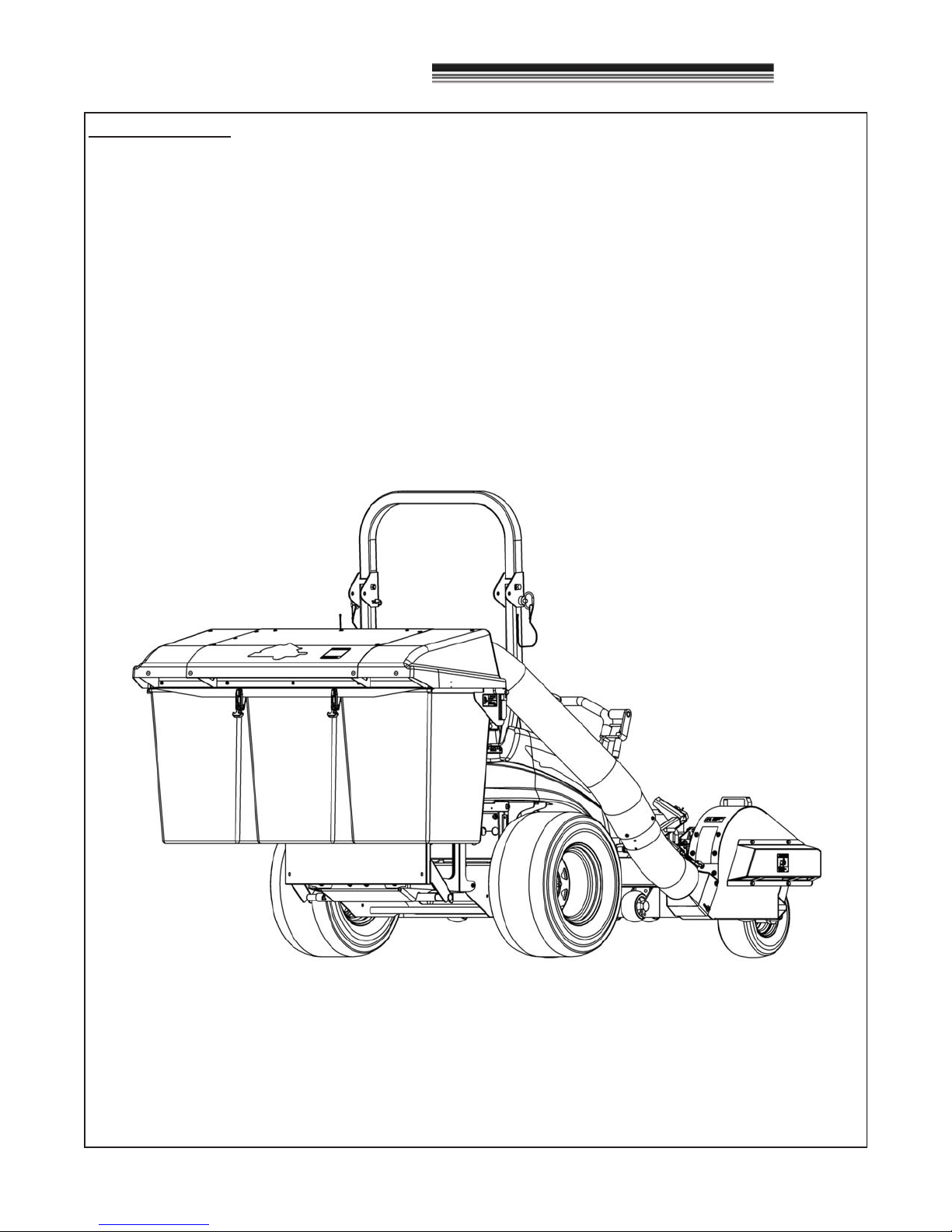
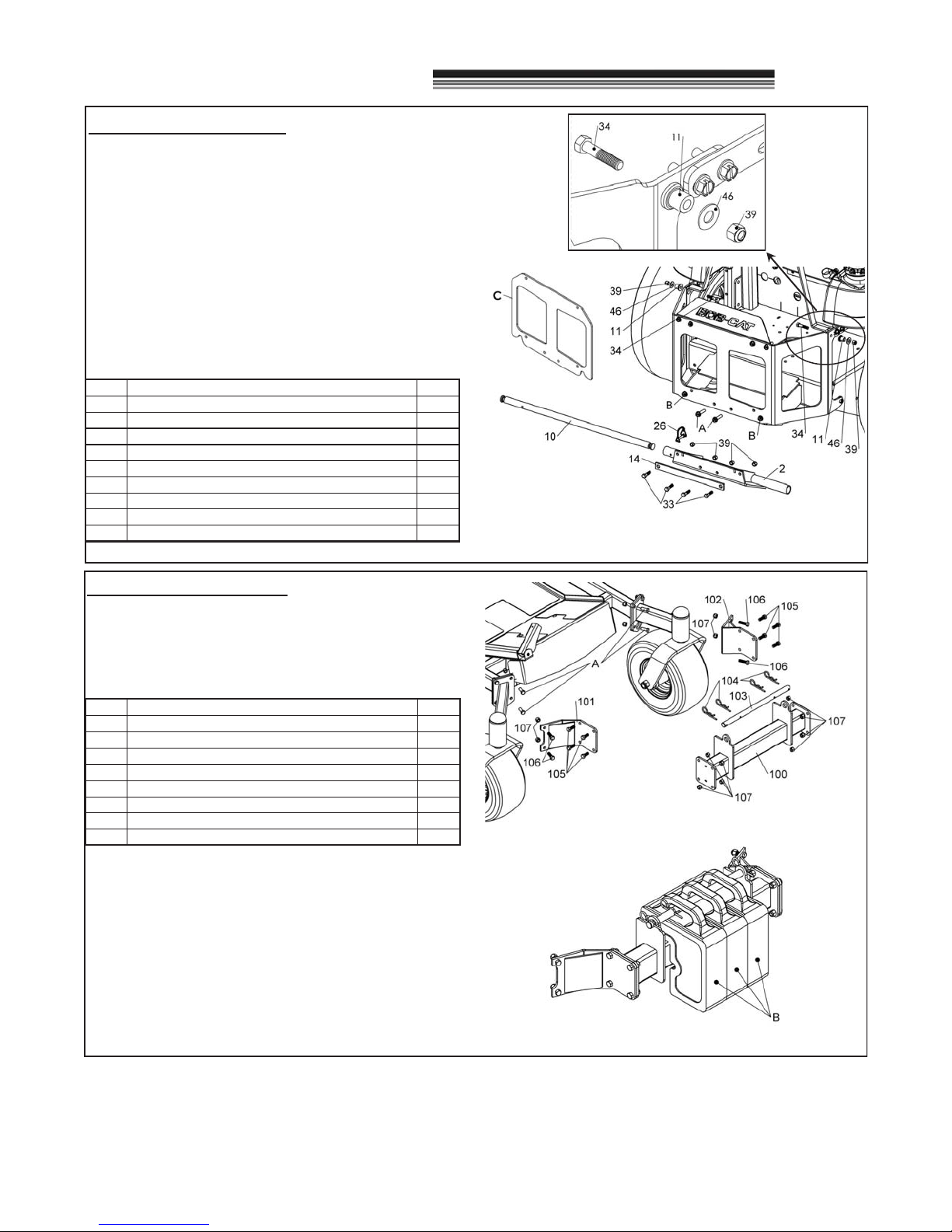
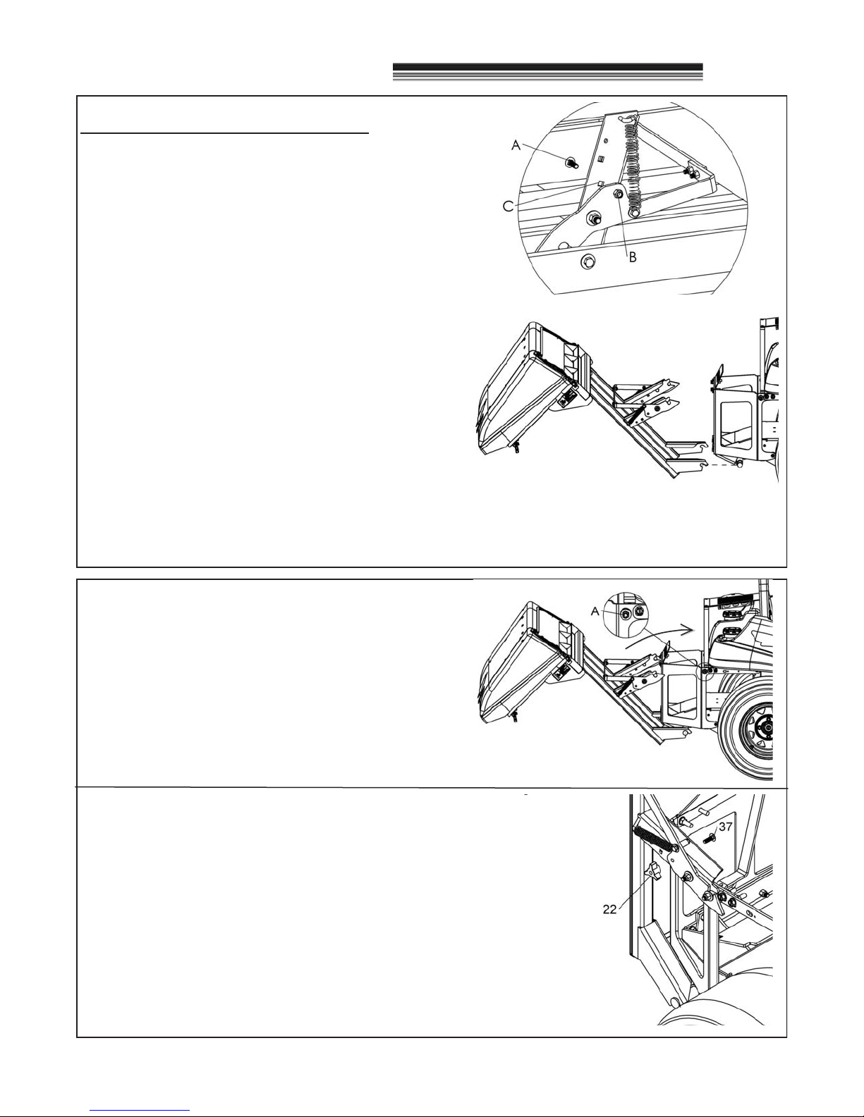
BAG COLLECTION SYSTEM