Important Safety Information
7/10/20 1
Important Safety Information
These are common practices that may or may not be applicable to the products described in
this manual.
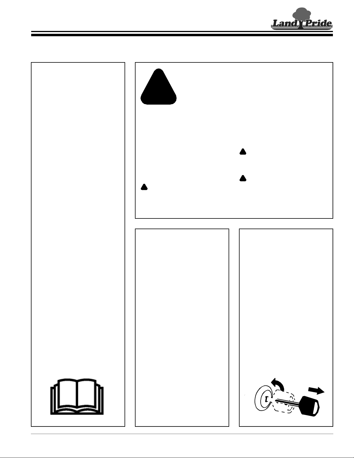
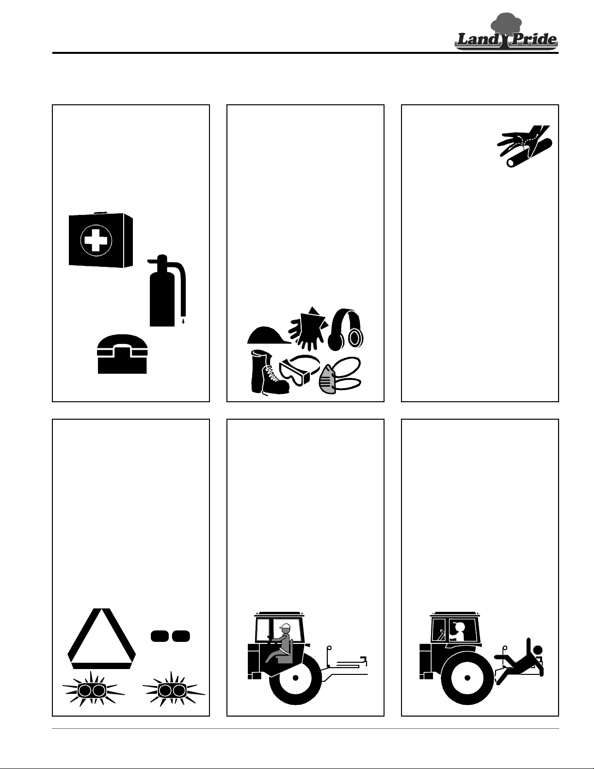
Tractor Shutdown & Storage
If engaged, disengage power
take-off.
Park on solid, level ground and
lower implement to ground or onto
support blocks.
Put tractor in park or set park
brake, turn off engine, and remove
switch key to prevent unauthorized
starting.
Relieve all hydraulic pressure to
auxiliary hydraulic lines.
Wait for all components to stop
before leaving operator’s seat.
Use steps, grab-handles and
skid-resistant surfaces when
getting on and off the tractor.
Detach and store implement in an
area where children normally do
not play. Secure implement using
blocks and supports.
OFF
REMOVE
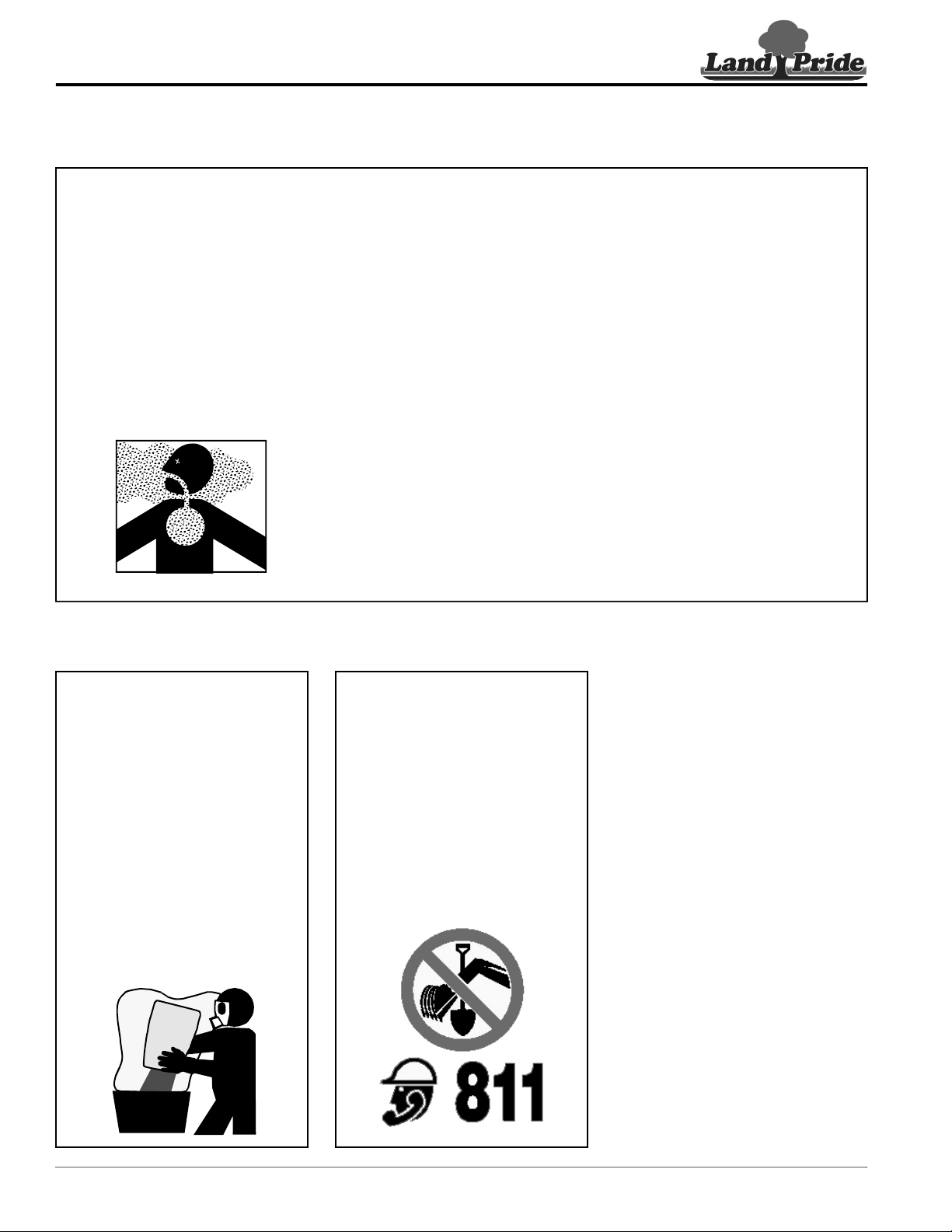
Look For The Safety Alert Symbol
The SAFETY ALERT SYMBOL indicates there is a
potential hazard to personal safety involved and extra
safety precaution must be taken. When you see this
symbol, be alert and carefully read the message that
follows it. In addition to design and configuration of
equipment, hazard control, and accident prevention are
dependent upon the awareness, concern, prudence, and
proper training of personnel involved in the operation,
transport, maintenance, and storage of equipment.
Safety Precautions for
Children
Tragedy can occur if the operator
is not alert to the presence of
children, Children generally are
attracted to implements and their
work.
Never assume children will remain
where you last saw them.
Keep children out of the work area
and under the watchful eye of a
responsible adult.
Be alert and shut the implement
and tractor down if children enter
the work area.
Never carry children on the tractor
or implement. There is not a safe
place for them to ride. They may
fall off and be run over or interfere
with the control of the power
machine.
Never allow children to operate the
power machine, even under adult
supervision.
Never allow children to play on the
power machine or implement.
Use extra caution when backing
up. Before the tractor starts to
move, look down and behind to
make sure the area is clear.
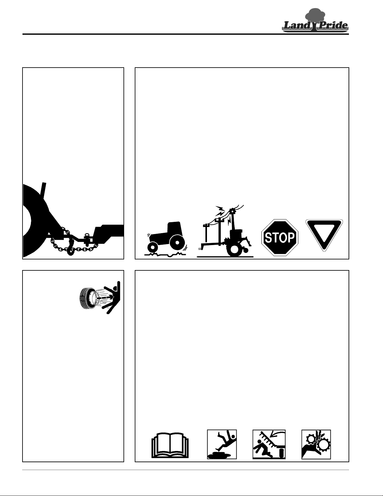
Safety at All Times
Careful operation is you best
insurance against an accident.
All operators, no matter how much
experience they may have, should
carefully read this manual and
other related manuals before
operating the power machine and
this implement.
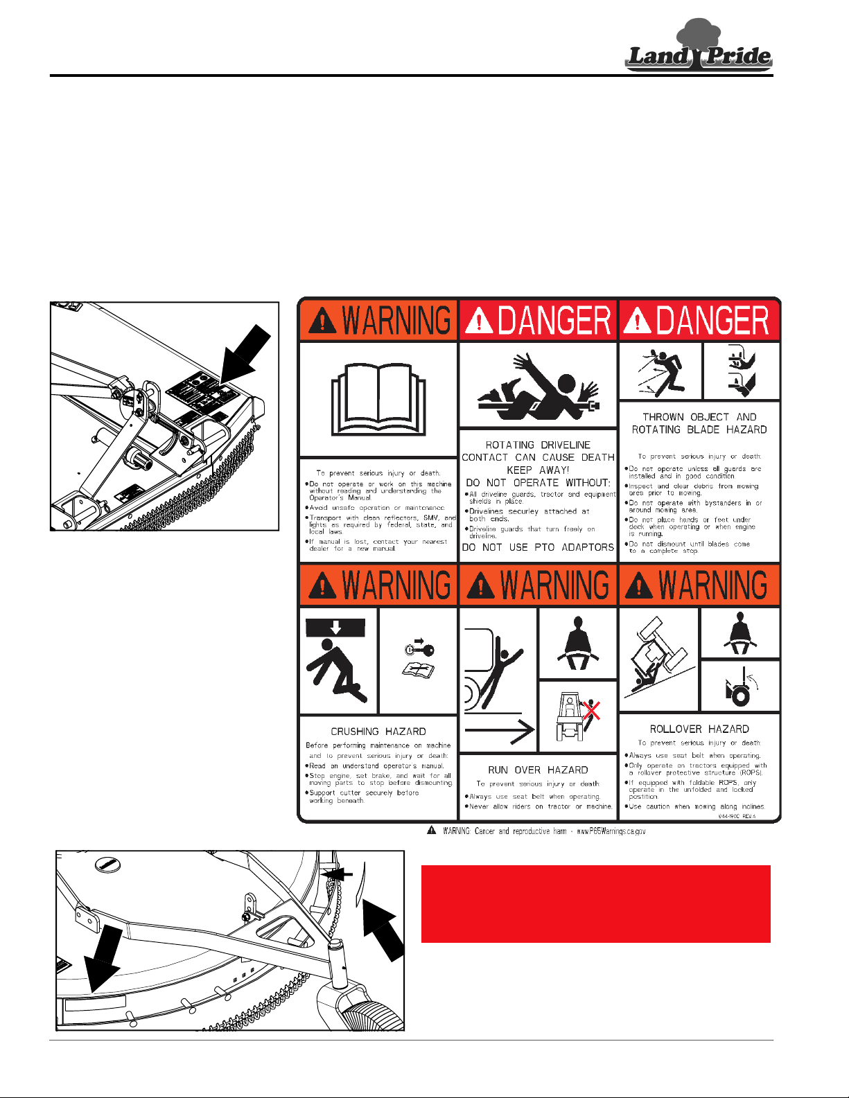
Thoroughly read and understand
the “Safety Label” section, read all
instructions noted on them.
Do not operate the equipment
while under the influence of drugs
or alcohol as they impair the ability
to safely and properly operate the
equipment.
The operator should be familiar
with all functions of the tractor and
attached implement, and be able
to handle emergencies quickly.
Make sure all guards and shields
are in place and secured before
operating implement.
Keep all bystanders away from
equipment and work area.
Start tractor from the driver’s seat
with hydraulic controls in neutral.
Operate tractor and controls from
the driver’s seat only.
Never dismount from a moving
tractor or leave tractor unattended
with engine running.
Do not allow anyone to stand
between tractor and implement
while backing up to implement.
Keep hands, feet, and clothing
away from power-driven parts.
While transporting and operating
equipment, watch out for objects
overhead and along side such as
fences, trees, buildings, wires, etc.
Do not turn tractor so tight as to
cause hitched implement to ride
up on the tractor’s rear wheel.
Store implement in an area where
children normally do not play.
When needed, secure implement
against falling with support blocks.
!
Be Aware of
Signal Words
A signal word designates a degree or
level of hazard seriousness. The
signal words are:
Indicates a hazardous situation that, if
not avoided, will result in death or
serious injury.
Indicates a hazardous situation that, if
not avoided, could result in death or
serious injury.
Indicates a hazardous situation that, if
not avoided, may result in minor or
moderate injury.
WARNING
CAUTION
!
!
DANGER
!