BOB Gear REVOLUTION User manual

UGA08C
BOB Gear
®
by Britax (888) 427-4829 or (704) 409-1699
4140 Pleasant Road, Fort Mill, South Carolina 29708
www.bobgear.com
BRITAX®, BOB®, BOB Gear®, and REVOLUTION®are trademarks owned by Britax and
registered in the U.S.A. and other countries. All Rights Reserved. STROLLER STRIDES® is a
registered trademark of Stroller Strides LLC., used by permission.
BRITAX®, BOB®, BOB Gear®, et REVOLUTION® sont des marques de commerce de Britax
enregistrées aux États-Unis et autre pays. Tous droits réservés. STROLLER STRIDES® est
une marque de commerce de Stroller Strides LLC., utilisé avec permission.
READ THESE INSTRUCTIONS COMPLETELY!
If you are unclear on any point, contact your dealer or Britax
Child Safety, Inc. before use. For a list of dealers, visit
www.bobgear.com or call (888) 427-4829 or (704) 409-1699.
Si vous avez besoin de précisions, veuillez contacter votre
distributeur agrée ou Britax Child Safety, Inc. avant d’utiliser
votre poussette. Pour obtenir la liste des revendeurs, visitez
www.bobgear.com ou composez le (888) 427-4829 ou (704) 409-1699.
LIRE ATTENTIVEMENT CES INSTRUCTIONS!
REVOLUTION®STROLLER
SE, CE, STROLLER STRIDES®, FLEX, PRO
ENGLISH Instruction Manual
FRANÇAIS Manuel d’utilisation

2
UGA08C
WARNINGS
FAILURE TO FOLLOW THESE WARNINGS AND ASSEMBLY
INSTRUCTIONS COULD RESULT IN SERIOUS INJURY OR DEATH.
• Read these instructions carefully before using this product. To ensure proper
use, store this user guide in a convenient place so it can be consulted often.
• Use extreme caution when using stroller on uneven and/or unpaved, wet or
slick surfaces, as these conditions create additional hazards and can lead to
a loss of stability resulting in serious injury.
• Avoid serious injury from falling or sliding out. Always use seat harness.
• Never leave child unattended.
• Never allow child to stand in stroller. Stroller can tip over.
• Child may slip into leg openings and strangle. Never use in reclined carriage
position unless child is harnessed.
• Wheel can detach and cause tip over. Pull on the wheel to assure it is
securely attached.
• Before running, jogging, or walking fast, LOCK the front wheel from swiveling.
• Do not modify the stroller or any labels. Doing so voids the warranty and
could lead to a dangerous condition.
• The maximum weight capacity of the stroller is 70 lbs (32 kg) (child plus
luggage weight). Maximum child height is 44 inches or (112 cm). Do not
exceed the maximum weight or height, as stroller will become unstable and
tip resulting in serious injury.
• Always use wrist strap to prevent being separated from stroller.
• Do not attach parcels or bags to the handlebar or frame of stroller except
those recommended by Britax, as stroller can become unstable and tip over.
• Do not park on inclines. The parking brake is intended to park the stroller on
flat surfaces only. Parking on inclines may result in tip over or runaway stroller.
• Never use with low tire pressure or deflated tires as this could result in loss
of control.
• Do not use stroller on stairs, escalators, or steep inclines. Stroller can tip over.
• Do not wear roller skates or inline skates while pushing stroller.
• Avoid finger entrapment or injury. Always ensure any child occupants or
bystanders are away from the stroller while folding or unfolding.
• The parking brake is not designed as a stopping brake. The parking brake
should not be used to slow or stop the stroller because doing so could cause
the stroller to stop abruptly, resulting in loss of control.
• Never load or unload the stroller without the parking brake set.
• Always jog with the stroller seat in the fully upright position. Jogging with
the seat in reclined positions may result in a loss of stability.
• Inflating tires above the maximum inflation pressure embossed on the tire
can damage rim and or tire resulting in loss of control and injury.

3
UGA08C
• Before and during use, always make sure the child’s hands and feet are away
from wheels.
• Never pull stroller backward up stairs. Doing so could damage the suspension
system, leading to frame failure.
• Protect stroller when transporting or shipping to prevent damage to stroller and
stroller components. Check closely for damage after transporting or shipping.
• Do not place sharp objects in the seat back pocket. Leaning against sharp
objects in seat back pocket can result in injury to occupant.
• Discontinue using stroller if damaged or if any parts are missing.
• When seat is fully reclined, the stroller is more likely to tip over backwards.
• Actual product may vary from images.
IMPORTANT NOTES
CONGRATULATIONS
Congratulations on your purchase of the BOB®Stroller.
Britax recommends that you register your stroller at www.britaxusa.com/bob-
registration. This will allow us to notify you directly if there are any product
recalls.
For updates to this manual, warranty and other recent product notifications,
please visit www.bobgear.com periodically or any time before making approved
changes or adding approved equipment to your stroller.

4
UGA08C
WARNINGS
TABLE OF CONTENTS
STROLLER ANATOMY
AGE GUIDELINES
STROLLER ASSEMBLY
Unpack Stroller
Wheels
Quick Release, Clamping Lever Function
Rear Wheel Installation
Removing Rear Wheel
Front Wheel Secondary Retention Devices
Front Wheel Installation
Removing Front Wheel
Unfold Stroller
Fold Stroller
STROLLER ADJUSTMENTS
Choose Walk or Jog Mode
Check Tire Pressure
Adjust Tracking
Fine Tune Tracking
Select Shock Setting
Setting Parking Brake
Secure Child In Seat
Attach Wrist Strap
Recline Seat
Position Canopy
Accessory Adapter
ADJUSTABLE HANDLE: FLEX & PRO MODELS
HAND BRAKE SYSTEM: PRO MODEL
CARE AND MAINTENANCE
Cleaning
Regular Inspections
STORAGE
CARGO
STROLLER ACCESSORIES
LIMITED WARRANTY
TABLE OF CONTENTS
Page 2
Page 4
Page 5
Page 6
Page 6
Page 6
Page 6
Page 7
Page 7
Page 8
Page 9
Page 9
Page 10
Page 11
Page 11
Page 12
Page 12
Page 12
Page 13
Page 13
Page 14
Page 14
Page 15
Page 16
Page 16
Page 17
Page 17
Page 18
Page 18
Page 21
Page 21
Page 21
Page 21
Page 21
Page 21
Page 22

5
UGA08C
Parking Brake
Rear Wheel
Clamping Lever
Seat Back Pocket
Frame Release
Handle
Wrist Strap
Rear Wheel
Retention Button
(PRO model only)
Brake Cable
(PRO model only)
Brake Cable
(PRO model only)
Adjustable
Handlebar
(FLEX & PRO
Models)
Handlebar
Release Lever
Canopy
Swivel Knob
Tracking Knob
Shock Release
Knob
Quick Release
Lever
Swing Arm
Seat Harness
Low Boy
Cargo Basket
Hand Brake
(PRO model only)
Drum Brake
(PRO model only)
STROLLER ANATOMY
REVOLUTION STROLLER SE, CE, STROLLER STRIDES, FLEX, PRO
•Actual product may vary from images

6
UGA08C
AGE GUIDELINES
Prior to first use, consult with your
pediatrician regarding suitability of
stroller use with your child. Britax
recommends that your child should be
at least 8 weeks old before riding in a
BOB stroller without a BOB Infant Car
Seat Adapter and compatible infant car
seat. Please note that infants incapable
of holding their head up must have
additional head and neck support to ride
safely and comfortably. With the addition
of the BOB Infant Car Seat Adapter and
compatible infant car seat, newborns
may be able to ride in the stroller.
For jogging or off-road stroller use,
Britax suggests children be at least
8 months old, or as directed by your
pediatrician. Children are unique and
develop at different rates. Most may not
have the neck strength for jogging or
off-road motion until 8 months of age.
Please refer to the below table for
age/use guidelines:
SUGGESTED USE AGE
Infant Car Seat
Adapter (Walk Only) 0 - 8 Weeks
See BOB Infant Car Seat Adapter Manual
for maximum occupant weight.
Walk Only 8 Weeks - 8 Months
Jogging/Off-Road 8 Months - 5 Years
STROLLER ASSEMBLY
UNPACK STROLLER
Remove stroller and wheels from box.
Front wheel is stowed in folded stroller.
Remove
all packaging materials and discard to
avoid choking and suffocation
hazards.
WHEELS
Before attempting to install wheels, read
warnings and instructions completely.
Using
your stroller with an improperly
adjusted wheel quick release lever
can allow the wheel to vibrate,
wobble or become detached from
the stroller. This can result in serious
injury or death. Accordingly, it is
critical that you:
• Ask your dealer to instruct you
on the proper technique for
safely installing and removing
your wheels.
• Use the proper method for
securely clamping a wheel to
the stroller using a quick release
lever.
• Check to make sure the wheels
are securely clamped before
each use of the stroller.
• Watch the instructional video on
Quick Release Wheel Installation
at www.bobgear.com.
The wheel quick release lever is a
device that supplies the clamping force
required to hold the stroller wheel
securely in place. To safely secure
a wheel to the stroller, it is critical
that you understand how the quick
release works, how to use and adjust
it properly and the amount of force
necessary to safely secure the wheel.
The
quick release lever is not a wing nut
system and turning the lever while
holding the tension adjusting nut does
not supply the required force to safely
clamp the wheel in the dropouts.
WARNING
WARNING
WARNING

7
UGA08C
2. Open Rear Wheel Clamping
Lever
Rotate the clamping lever into the
fully open position so it curves away
from the rear wheel attachment
bracket.
3. Insert Rear Wheel Stub Axle
Insert the rear wheel’s stub axle into
the hole in the rear dropout. If the
axle does not slide in easily, loosen
the quick release tension adjusting
nut by hand. Re-insert the axle fully
into the rear dropout until the axle
shoulder or snap ring on the axle
comes in contact with the attachment
bracket.
ATTENTION! If you have the
PRO model, see pg. 20 for rear
wheel installation.
QUICK RELEASE, CLAMPING
LEVER FUNCTION
The rear wheels are correctly clamped
in place by the force generated when
the clamping lever is closed and the
cam action pulls the axle against the
attachment bracket, securing it in place.
The front wheel is correctly clamped
in place by the force generated when
the quick release lever is closed and
the cam action pulls the lever housing
against one dropout, and pulls the
adjusting nut against the other dropout,
clamping the hub between the
dropouts.
The tension adjusting nut sets the
amount of clamping force. Turning
the tension adjusting nut in the
clockwise direction while preventing
the quick release lever from rotating,
increases the amount of clamping
force. Alternatively, turning the tension
adjusting nut counterclockwise, while
preventing the quick release lever
from rotating, reduces the amount of
clamping force. The tension adjusting
nut only needs minor adjustments to
provide the correct clamping force, less
than a half turn can mean the difference
between safe and unsafe clamping
force.
REAR WHEEL INSTALLATION
1. Unlock Parking Brake
Prior to installing the rear wheels,
position the parking brake in the
unlocked position.
Tension Adjusting Nut
Stub Axle
Rear Wheel
Attachment
Bracket
Folded Position
Rear Wheel
Clamping Lever

8
UGA08C
4. Adjust Rear Wheel Clamping
Lever
To adjust the clamping lever, hold the
clamping lever in the FULLY OPEN
position with your right hand, and
tighten the tension adjusting nut with
your left hand until it is finger tight
against the attachment bracket.
To TIGHTEN tension adjusting nut,
turn clockwise.
FULLY CLOSED
To properly close the clamping lever
and secure the rear wheel in the
attachment bracket, confirm the axle
is fully inserted in the attachment
bracket, while maintaining the wheel
in this position, rotate the clamping
lever toward stroller and into the FULLY
CLOSED position.
To generate enough clamping force
it is necessary to wrap your fingers
around the attachment bracket while
closing the clamping lever. The proper
force required to close the clamping
lever should leave a visible imprint in
the palm of your hand.
If the clamping lever cannot be rotated
to the FULLY CLOSED position, rotate
the lever to the FULLY OPEN position
and turn the tension adjusting nut a
quarter turn counterclockwise. Repeat
the closing process.
IMPORTANT: It takes considerable
force to securely clamp the wheel.
If you are able to completely
close the clamping lever without
wrapping your fingers around
the attachment bracket and the
clamping lever does not leave
a visible imprint in the palm of
your hand, the tension is not
adequate. Rotate the lever to the
FULLY OPEN position and turn the
tension adjusting nut a quarter
turn clockwise and repeat the
closing process.
To LOOSEN tension adjusting nut,
turn counterclockwise.
REMOVING REAR WHEEL
1. Unlock Parking Brake
Prior to removing the rear wheels,
position the parking brake in the
unlocked position.
2. Open Rear Wheel Clamping
Lever
Move the wheel’s clamping lever
from the locked or FULLY CLOSED
position to the FULLY OPEN position.
FULLY CLOSED
FULLY OPEN
FULLY CLOSED

9
UGA08C
3. Remove Wheel
Raise the wheel a few inches off the
ground and pull the wheel out of the
rear wheel attachment bracket.
ATTENTION! If you have
the PRO model, see pg. 20 for
removing rear wheel.
FRONT WHEEL SECONDARY
RETENTION DEVICES
Your stroller fork utilizes secondary
wheel retention devices designed
to help keep the wheel from
disengaging from the fork if the
quick release is incorrectly adjusted
and tightened. The wheel can still
remain loose and wobbly even with
the secondary retention device
working if the quick release has
not been properly tightened and
adjusted. The secondary retention
devices are backup systems and are
not intended as a substitute for a
properly adjusted quick release. The
secondary retention devices on your
stroller are the integral type that are
formed into the outer faces of the
fork dropouts.
Dropouts
(Secondary Retention Devices)
IMPORTANT: Using your stroller
with an improperly adjusted and
tightened wheel quick release can
allow the wheel to vibrate, wobble
or become detached from the
stroller. This can result in serious
injury or death.
It is critical that you do not remove
or disable the secondary retention
devices. The secondary retention
devices can reduce the risk of the
wheel disengaging from the fork
if the quick release is not adjusted
and tightened correctly. Removing
or disabling the secondary
retention devices will void the
warranty.
FRONT WHEEL INSTALLATION
1. Rotate Quick Release Lever
Rotate quick release lever so that
it curves away from the wheel. This
places it in the FULLY OPEN position.
O
P
E
N
Quick Release Lever
FULLY OPEN FULLY CLOSED

10
UGA08C
2. Insert Front Wheel
When facing the front of the stroller,
insert the wheel between the fork
dropouts so that the axle firmly con-
tacts the top of the slots of the fork
dropouts.
3. Adjust Quick Release Lever
To adjust the quick release, hold the
quick release cam lever in the FULLY
OPEN position with your right hand
as shown. Tighten the tension adjust-
ing nut with your left hand until it is
finger tight against the fork dropout.
4. Close Quick Release Lever
To properly close the quick release and
secure the front wheel in the dropouts,
confirm the axle is contacting the top
of the dropouts on both sides and the
wheel is centered left to right.
While maintaining the wheel in this
position, rotate the quick release
upward and into the FULLY CLOSED
position. When properly closed, the
curve of the quick release will be
pointing toward the wheel and parallel
to the fork blade. To generate enough
clamping force it is necessary to wrap
your fingers around the fork blade
while closing the quick release lever.
The proper force required to close the
quick release lever should leave a visible
imprint in the palm of your hand.
IMPORTANT: It takes considerable
force to securely clamp the wheel.
If you are able to completely close
the quick release without wrapping
your fingers around the fork blade
and the quick release lever does not
leave a visible imprint in the palm
of your hand, the tension is not
adequate. Rotate the lever to the
FULLY OPEN position and turn the
tension adjusting nut a quarter turn
clockwise and repeat the closing
process.
If the quick release lever cannot
be rotated to the FULLY CLOSED
position, rotate the lever to the
FULLY OPEN position and turn the
tension adjusting nut a quarter
turn counterclockwise. Repeat the
closing process.
REMOVING FRONT WHEEL
1. Open Quick Release Lever
Move the wheel’s quick release lever
from the locked or FULLY CLOSED
position to the FULLY OPEN position.
Your front fork has integral secondary
retention devices that require loosen-
ing the tension adjusting nut enough
to allow removal of the wheel.
Quick Release Lever
Tension Adjusting Nut
Dropout
FULLY OPEN
FULLY CLOSED
Dropouts
Fork Blade

11
UGA08C
2. Remove Front Wheel
Raise the front wheel a few inches off
the ground and tap the top of the
wheel with the palm of your hand to
knock the wheel out of the front fork.
UNFOLD STROLLER
1. Lift Red Frame Release Handle
Keep tires on ground as stroller swing
arm begins to swing open.
NOTE: Stroller swing arm will swing
open and “snap” into an open and
locked position.
2. Rotate Handlebar
Lift handlebar up and back until it
“snaps” into locked and upright position.
FOLD STROLLER
1. Lock Parking Brake
Set parking brake in locked position.
2. Remove Child From Seat
3. Empty Stroller
Remove contents from low boy cargo
basket and pockets.
4. Rotate Handlebar
Squeeze both handlebar release
levers simultaneously. Rotate
handlebar forward onto seat.
5. Lift Red Frame Release Handle
Using a short, quick tug, lift red frame
release handle up. Keep tires on
ground as stroller collapses toward
front wheel. (see image next page)
SNAP SNAP
SNAP SNAP

12
UGA08C
6. Lay Stroller Flat
7. Secure Folded Stroller
Use wrist strap buckle to secure
stroller in folded position.
8. Make It Smaller
Take off the front and rear wheels to
make it even smaller. See Removing
Rear Wheel and Removing Front
Wheel sections.
STROLLER ADJUSTMENTS
CHOOSE WALK OR JOG MODE
If front fork is in “JOG MODE” front
fork will be locked and the front fork/
wheel will not swivel left or right as it
does in “WALK MODE”.
IMPORTANT: Never run, jog, or
walk fast with the stroller in walk
mode. Doing so could result in loss
of control and serious injury.
WALK MODE (Walking)
Slide swivel knob up and to the left.
Fork will now rotate 360 degrees.
NOTE: Stroller is shipped with front
wheel in walk mode.
JOG MODE (Jogging/Off-Road)
Slide swivel knob upward and to the
right. Knob will slide into downward
position. Rotate fork/wheel until it
“snaps” into forward position.
WALK MODE JOG MODE
SNAP
CHECK TIRE PRESSURE
Plastic wheels are rated to a
maximum tire inflation pressure of
30 pounds per square inch (psi).
The maximum inflation pressure is
embossed on the wheel next to the
valve stem.
Handlebar

13
UGA08C
ADJUST TRACKING
If stroller pulls left or right when
the front wheel is in jog mode and
stroller is on flat terrain, adjust
tracking as outlined in the following
steps. Do not roll test with a child
or any occupant in the stroller.
1. Empty Stroller
Remove contents from low boy cargo
basket and pockets.
2. Check Tire Pressure
3. Set Stroller to Jog Mode
Slide swivel knob to right. Knob will
slide into downward position. Rotate
fork/wheel until it “snaps” into
forward position. See Choose Walk
or Jog Mode section.
4. Place Stroller On Level Ground
Find a stretch of level ground about
16 feet long.
16 ft
5. Align Rear Wheel Axles
Align stroller so rear wheel axles are
perpendicular to a straight line.
6. Test Alignment
Push stroller straight forward and
release to see if stroller veers right or
left. Repeat push test several times.
If stroller consistently pulls to left or
right, proceed to Fine Tune Tracking.
FINE TUNE TRACKING
If Stroller Pulls LEFT
If your stroller pulls LEFT, turn
tracking knob counterclockwise up to
one half turn.
If Stroller Pulls RIGHT
If your stroller pulls RIGHT, turn
tracking knob clockwise up to one
half turn.
REPEAT roll test and adjust as
needed until stroller rolls straight.
Tracking Knob
Tracking Knob

14
UGA08C
SELECT SHOCK SETTING
1. Remove Child From Seat
2. Set Shock Setting To Position 2
Depress shock release knob and
simultaneously pull toward back of
stroller, sliding knob into position 2.
Knob will “snap” into place when in
correct position.
REPEAT on opposite side.
Position 1: Child 40 pounds or less
40 lbs
SNAP
Position 2: Child 41 to 70 pounds
70 lbs
41 lbs
SNAP
NOTE: Every time stroller is folded,
stroller shocks default to position 1.
SETTING PARKING BRAKE
The parking brake prevents the
stroller from moving while loading
and unloading. The parking brake is
not designed as a stopping brake.
IMPORTANT: Do not park on
inclines. The parking brake is
intended to park the stroller on flat
surfaces only. Parking on inclines
may result in tip over or runaway
stroller.
To set the parking brake, press down
on the red foot pedal – making sure
the locking pin fully engages the
locking disk.
LOCKED POSITION
To ensure the brake is set properly,
attempt to roll the stroller forward and
backward after setting the brake. If
the stroller will not roll, the brake is set
properly.
To release the parking brake, lift up
on the red foot pedal with your foot
until the brake bar springs up into
the fully unlocked position.
UNLOCKED POSITION

15
UGA08C
SECURE CHILD IN SEAT
1. Set Parking Brake
Rotate parking brake down into
locked position.
NOTE: Rear wheels should not rotate
when parking brake is set.
2. Place Child In Seat
Slip one shoulder strap over each
shoulder. Position crotch strap
between legs.
3. Fasten Shoulder Straps
Insert both shoulder strap buckles
into crotch strap buckle.
NOTE: Crotch strap should be
adjusted to have a snug fit.
Crotch Strap Buckle
4. Adjust Shoulder Strap Height
Adjust height of shoulder strap to fit
just above child shoulder height.
5. Adjust Shoulder Straps
Open pads with hook and loop
fasteners. Slide buckle up or down to
adjust straps. Seat harness should fit
snug and be comfortable.
6. Tighten Lap Straps
Adjust lap straps to fit snug and be
comfortable.
Lap Strap
Crotch Strap
Shoulder Strap

16
UGA08C
ATTACH WRIST STRAP
The wrist strap is designed to help
prevent the stroller from rolling away
should you lose your grip on the stroller.
When using the stroller, make sure the
strap is securely looped over your wrist.
Failure
to attach wrist strap can result in
loss of control of the stroller.
1. Slip loop of strap securely onto
wrist.
RECLINE SEAT
IMPORTANT: Set parking
brake before making any seat
adjustments.
1. Recline Seat
Pull up on seat recline buckle to
loosen recline straps.
2. Return To Upright Position
To raise seat, lift seat back with one
hand and pull recline strap down with
other hand.
3. Repeat on opposite side.
IMPORTANT: When seat is fully
reclined, backward tip over is more
likely to occur and may result in
an accident or injury, as seat and/
or passenger may contact ground
before handlebar.
Seat Recline
Strap
Seat Recline
Buckle
WARNING

17
UGA08C
POSITION CANOPY
1. Extend Canopy
Rotate canopy away from handlebar
for additional shade.
2. Retract Canopy
Push canopy toward handlebar.
ACCESSORY ADAPTER
This BOB stroller is equipped with
an accessory adapter providing
easy attachment for BOB Stroller
accessories like the Snack Tray or
Infant Car Seat Adapter.
Attaching BOB accessories is simple
and easy with this push button, lock
and release design. The accessory
adapter also allows for many
accessories to remain attached when
the stroller is folded. See Stroller
Accessories section of this manual
for more information on all available
accessories.

18
UGA08C
ADJUSTABLE HANDLE
(FLEX & PRO MODELS)
To adjust the handle position, depress
and hold the two release buttons on
the inside of the handle assembly
while raising or lowering the handle to
one of the individual positions.
ATTENTION! For FLEX and PRO
models, ensure the handle is
positioned parallel to the ground
before folding.
HANDBRAKE SYSTEM
(PRO MODEL)
The hand brake system is connected
to rear drum brakes and may be used
to help slow or stop a stroller. The hand
brake system is not a parking brake.
Brake Lever
Drum Brakes
Brake Cable
The hand brake system is equipped with
two barrel adjusters. If you are not familiar
with how to use the barrel adjusters,
please contact Britax customer service or
visit your local dealer for assistance.
HAND BRAKE (PRO Model)
DRUM BRAKE (PRO Model)
ESTABLISH CORRECT FUNCTION
For the hand brake system to work
correctly, it is critical that it be
adjusted properly. With the braking
system properly adjusted, the wheels
should freely rotate when the brake
lever is not engaged. To establish
if the braking system is functioning
correctly:
•Check to see if proper brake force
is applied when the brake lever is
pulled to within 1/2” or more from
the handlebar.
•Check to see if the brake force is
balanced (evenly applied), between
both the right and left rear wheels.
Hand Brake Lever Lock Ring
Barrel Adjuster
Handlebar
Drum
Brake Pads
Lock Ring
Barrel Adjuster

19
UGA08C
1. Adjust Brake Force
If correct brake force is not applied
when the brake lever is pulled to
within 1/2” of the handle bar, then the
brake cable will need to be
tightened. To tighten the cable,
loosen the lock ring on the brake
lever and turn the barrel adjuster in a
counter clockwise direction. Secure
the barrel adjuster in the new position
by tightening the lock ring against the
brake lever body.
If the rear wheels do not spin freely
when the brake lever is in the
released position, then there is too
much brake force and the brake
cable will need to be loosened. To
loosen the cable, loosen lock ring
and turn the barrel adjuster in a
clockwise direction. Secure the barrel
adjuster by tightening the lock ring
against the brake.
Continue these adjustments until
proper braking force is established
on at least one of the rear wheels.
Lock Ring
Barrel Adjuster
2. Balance Brake Force
Identify the wheel that does not have
enough brake force. Locate the drum
brake barrel adjuster on that side.
Tighten the brake cable (as in step
one), until the brake force is equal to
that of the opposite wheel.
NOTE: Adjustment of the drum
brake barrel adjusters requires a
wrench.
NOTE: There are lock rings on all
barrel adjusters to stop them from
changing their position. Always make
sure the lock rings are tightly fastened
after making adjustments.
NOTE: Ensure that all brake cable
ends are properly located in the
relevant hole of the barrel adjusters.
Lock Ring
Barrel Adjuster
Lock Ring
Barrel Adjuster

20
UGA08C
IMPORTANT: Ensure that the gap
between the barrel adjuster and the
lock ring does not exceed 5mm. If
the gap exceeds 5mm, there is a
risk that the screw will shear with
potential loss of braking function.
REAR WHEEL INSTALLATION
(PRO MODEL)
Follow steps 1 and 2 from (REAR
WHEEL INSTALLATION)
section on page 7.
3. Insert Rear Wheel Stub Axle
Insert the rear wheel’s stub axle into
the hole in the rear wheel attachment
bracket. If the axle does not slide
in easily, loosen the clamping lever
tension adjusting nut by hand. Re-
insert the axle fully into the attachment
bracket until a “click” is heard. Adjust
tension nut and close clamping lever
as described in step 4 on page 8.
REMOVING REAR WHEEL
(PRO MODEL)
Follow steps 1 and 2 from
(REMOVING REAR WHEEL)
section on page 7.
3. Remove Wheel
While pressing the rear wheel retention
button, raise the wheel a few inches off
the ground and pull out from the rear
wheel attachment bracket.
IMPORTANT: Ensure there is a click
upon fully inserting the wheel. If no
click is heard, there is a possibility
that the wheel is not secure in the
attachment bracket and it may fall
off during operation.
Rear Wheel
Retention Button
CLICK
Stub Axle Rear Wheel
Attachment
Bracket
5mm
3/16”
max.
Brake Backplate
5mm
3/16”
max.
Lock Ring
Barrel Adjuster
This manual suits for next models
12
Table of contents
Languages:
Other BOB Gear Stroller manuals
BOB Gear
BOB Gear IRONMAN User manual
BOB Gear
BOB Gear RENEGADE User manual

BOB Gear
BOB Gear Revolution SE Setup guide
BOB Gear
BOB Gear Revolution Duallie User manual
BOB Gear
BOB Gear WAYFINDER User manual
BOB Gear
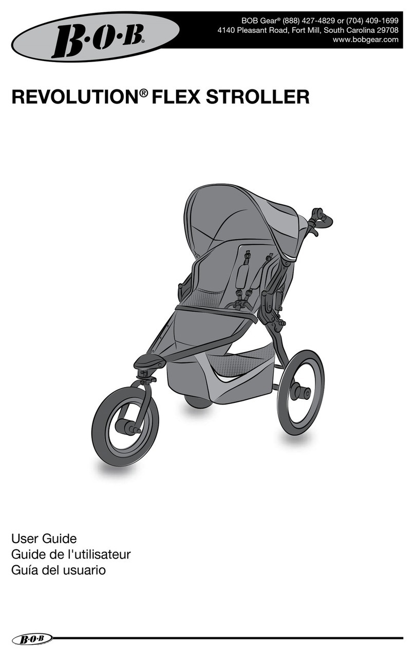
BOB Gear REVOLUTION FLEX User manual
BOB Gear
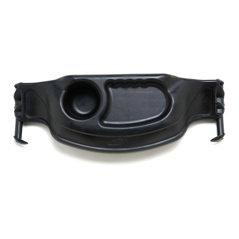
BOB Gear SNACK TRAY Single User manual

BOB Gear
BOB Gear Revolution Flex Duallie User manual
