Boca BocaVision STB121 User manual
OWNERS MANUAL
Model: STB121
BocaVision
Network Devices
with Citrix ICA®Support
®

2
Congratulations on your Purchase.
You are now the owner of BocaVisiontm by Boca Research, Inc. Before you
begin surfing the Net or accessing remote applications as a Windows-
based terminal, please review the contents of this manual to simplify the
installation process.The first section of this manual describes the product’s
features and how to connect the unit to your television set or a VGA
monitor.The balance of the manual will guide you through the features and
options of the network software and Internet Service Provider, as well as
other useful reference information.
Please locate the enclosed registration card, fill it out, and return
it.Registering your product enables us to better serve you in the
event your BocaVision unit requires service.
Boca Research is a leading manufacturer of data communications,
videoconferencing, multimedia, and networking products to facilitate the
transmission of information on PCs, networks, and/or the Internet.
Boca provides hardware products augmented with software for use in the
corporate, consumer, and small office/home office marketplaces, and sells
these products worldwide. Products are designed and manufactured in the
U.S.A. with domestic and foreign parts, backed by a limited warranty, and
various technical support options.
Boca Research’s WEB address: http://www.bocaresearch.com
Write down the following information for your reference:
Model No.______________
Serial No._______________
The model number is located on the front cover
of this owner’s guide.
The serial number is located on the bottom of
the unit.
3
READ THESE SAFETY INSTRUCTIONS
BEFORE INSTALLING AND OPERATING THIS
EQUIPMENT
TO REDUCE THE RISK OF ELECTRIC SHOCK, DO
NOT REMOVE COVER (OR BACK).THERE ARE NO
USER-SERVICEABLE PARTS INSIDE.OBTAIN
SERVICE FROM QUALIFIED SERVICE PERSONNEL.
Do not stack electronic components or any other
objects on top of the unit.The slots on top of the unit
must be left uncovered to permit necessary airflow to
the unit. Obstructing the airflow could impair
performance or damage other components.
Do NOT stack the unit on top of any other electrical
component which radiates heat (e.g., audio amplifier).
For proper operating voltage, check the identification/
rating label on the underside of the unit.
NOTE: FCC regulations state that unauthorized
changes to this product could void your authority to
operate it.
WARNING: Any changes to this unit, not approved by
Boca Research, Inc. may void your warranty.
Avoid electric shock and
fire hazard,keep this
equipment away from
moisture.

4
REGULATORY COMPLIANCE INFORMATION
Your BocaVision unit is registered with the Federal Communications Commission and complies with parts 15B and 68, FCC Rules and
Regulations.
1. NOTIFICATION TO THE LOCAL TELEPHONE COMPANY
On the bottom of this equipment is a label indicating, among other information, the FCC Registration number and Ringer Equivalence
Number (REN) for the equipment.Youmust, upon request, provide this information to your local telephone company.
The REN is useful in determining the number of devices you may connect to your telephone line and still have all these device ring when
your telephone number is called.In most (but not all) areas, the sum of the RENs of all devices connected to one line should not exceed
5.To be certain of the number of devices you may connect to your line as determined by the REN, you should contact your local
telephonecompany.
Notes:This equipment may not be used on coin service provided by the telephone company.
Party lines are subject to state tariffs, and therefore, you may not be able to use your own telephone equipment if you are on a party line.
Check with your local telephone company.
Notice must be given to the telephone company upon permanent disconnection of your equipment from your line.
2. RIGHTS OF THE TELEPHONE COMPANY
Should your equipment cause you trouble on your line which may harm the telephone network, the telephone company, where practicable
and the circumstances warrant such action, may temporarily discontinue service immediately. In case of such temporary discontinuance,
the telephone company must:(1) promptly notify you of such temporary discontinuance, (2) afford you the opportunity to correct the
situation, and (3) inform you of your right to bring a complaint to the Commission pursuant to procedures set forth in Subpart E of Part 68,
FCC Rules and Regulations.
The telephone company may make changes in its communications facilities, equipment, operations or procedures where such action is
required in the operation of its business and not inconsistent with FCC Rules and Regulations.If these changes are expected to affect the
use or performance of your telephone equipment, the telephone company must give you adequate notice, in writing, to allow you to
maintainuninterrupted service.
RADIO INTERFERENCE
This equipment has been tested and found to comply with the limits for a Class B digital device, in accordance with the specifications in
Part 15 of FCC rules.These rules are designed to provide reasonable protection against radio and television interference in a residential
installation.This equipment generates, uses, and can radiate radio frequency energy and, if not installed in accordance with the
instructions, may cause harmful interference to radio communications.However, there is no guarantee that interference will not occur in a
particular installation.If this equipment does cause interference to radio or television reception (which you can determine by turning the
equipment off and on), try to correct the interference by one or more of the following measures:
• Re-orient or relocate the receiving antennae (that is, the antenna for radio or television that is “receiving” the interference).
• Change the position of the unit with respect to the radio or television equipment that is receiving interference.
• Move the unit away from the equipment that is receiving interference.
• Plug the unit into a different wall outlet so that the unit and the equipment receiving interference are on different branch circuits.
If these measures do not eliminate interference, please consult your dealer, or an experienced radio/television technician for additional
suggestions. Also, the Federal Communications Commission has prepared a helpful booklet,“How to Identify and Resolve Radio/TV
Interference Problems”.This booklet is available from the U.S.Government Printing Office, Washington D.C.20202.Please specify stock
number 004-000-00345-4 when ordering copies.

5
Contents
Introduction...................................................... 6
Summary of Features ..............................................6
Getting Started................................................. 7
What’s in the Box?....................................................7
Connectors and LEDs ..................................... 8
Connections ..................................................... 9
Connecting the Unit - Common Installation ............9
Connecting to a TV or VCR without A/V Jacks .......10
Connecting to a TV with S-VIDEO...........................11
Connecting to a TV/VCR with A/V Jacks...............12
Connecting to a Wireless Keyboard ........................13
Connecting to a PS/2-Compatible Keyboard...........15
Connecting a Mouse ................................................15
Connecting a Printer to the Parallel Port ..................16
Connecting to a VGA Monitor ..................................16
Specifications .................................................. 17
Network Software............................................. 18
Introduction ................................................... 18
On-Screen Display ................................................18
Color Palette ..........................................................18
Screen Saver .........................................................18
Power Off Request ................................................18
Smart Card ............................................................19
Start-up Sequence ........................................ 19
Ready to Go Screen..............................................19
Welcome Screen ...................................................19
Smart Card Screens..............................................20
Begin Setup ........................................................20
Change ISP Details ............................................21
Change PIN ........................................................22
Invalid New PIN ..................................................23
Check for Smart Card ........................................23
Smart Card Not Inserted....................................23
Smart Card Not Valid..........................................24
Smart Card Damaged ........................................24
Check for Valid PIN.............................................25
PIN Screens...........................................................25
Enter PIN ............................................................25
Invalid PIN...........................................................25
Dialing Sequence...................................................26
Dialing Screens ............................................. 27
Modem Status Screens.........................................27
Modem Error Messages........................................27
Browser User Interface ................................. 29
Browser Toolbars.................................................29
Main Toolbar .........................................................29
Go To ....................................................................29
Secondary Toolbar ...............................................30
History ..................................................................30
Favorites ...............................................................31
Options .................................................................32
Print ......................................................................32
Print Frames .........................................................32
Toolbar Buttons ...................................................33
Progress Indicator...............................................33
Up/Down Arrows..................................................33
Web Page Links ...................................................33
Button Types ........................................................33
Submit Button ......................................................33
Check Boxes ........................................................33
Radio Buttons ......................................................33
Pop-up Menu Button ...........................................33
Text Entry Field....................................................33
Codec Controls ....................................................33
Secure Socket Layer (SSL) Indicator................34
Web Page Password Challenge .........................34
Image Map Cursor ...............................................34
Mouse Cursors.....................................................34
System Busy Indicator .......................................34
Frame Navigation Graphics ...............................34
Option Screens.............................................. 35
Text Options ...........................................................35
Printing Options .....................................................36
Screen Positioning Options ...................................36
Sound Options.......................................................36
Telephone Options.................................................37
Call Waiting Options ..............................................37
ICA®Support .................................................... 38
Troubleshooting............................................... 41
Compatible Printers......................................... 43
Accessories ...................................................... 44
Limited Warranty .............................................. 45
Servicing your Product ................................... 46
How to get Technical Assistance ................... 47
6
Welcome...
Our thanks for purchasing the Boca
Research, Inc. BocaVision®Network
Device. Designed as a television
accessory or desktop Network access
device*, this unit allows you to connect to
the Internet via your TV or VGA monitor
and a local standard analog telephone
line.
* See the section on Citrix ICA®Support
(page 38-40)
To access the Internet, you will need to
subscribe to an Internet Service Provider
(ISP); see pages 18-28. Connection
instructions are detailed on pages 8-16.
Summary of Features
Components
• BocaVision STB unit
• IR keyboard with joystick
mouse (batteries included)
• Owner's manual
• EZ Setup Guide
• Registration Card
• Smart card
• Cable pack
Connectors/Indicators
• Status LEDs: GREEN (power); RED
(connect)
• Telephone jack
• VGA port
• RCA composite video output
Introduction
• RCA right/left audio channels
• S-Video output
• Parallel port
• PS/2 keyboard port
• PS/2 mouse port
• Smart card slot
• Power connector
Features
Open ISP
Integrator's and/or user's choice for Internet
service provider relationship:
• Local Phone # • User Name
• Password • Domain name
• DNS information
• User-designated home page URL and web-
based email URL
Video • 640x480x8 bits @60Hz
• NTSC and VGA video mode
• Vertical flicker control
• Play AVI files
Audio • Real Audio
• WAV, AU, MIDI, SND, AIFF sound
files
Telephony
•
Call-waiting support with one-touch re-dial to
ISP connection following incoming call
Printer
• Bidirectional parallel port connection for over
150 models including HP, Epson, Lexmark,
Canon, Okidata, and more
Browser
• Full HTML 3.2 compatibility
• Dynamic horizontal scaling of Web pages
• SSL (Secure Socket Layer) encryption.
Provides data encryption, server
authentication, message integrity, and
optional client authentication for a TCP/IP
connection.
Cable Pack Includes:
• A/V cable (6 ft.)
• S-Video cable
•Telephone cable (25 ft.)
• Power Cord
•T-splitter
• Batteries (AA)

7
Whats in the Box?
Before making connections, review the
list below to ensure your package is
complete.
Getting Started
~
`
BACK
SPACE
+
=
_
-
)
0
(
9
*
8
&
7
^
6
%
5
$
4
!
1@
2#
3
{
[
}
]
|
\
PAGE
UP
ENTER
"
'
:
;
CAPS
LOCK
SHIFT
<
,
>
.
?
/
SHIFT
REC
TAB
ESC CTRL ALT WHO PRINT RELOAD FAV SAVE GO TO SEARCH SEND MAIL HOME
PAGE
DOWN
STOP
MENU
GUIDE
PAUSE REV PLAY FWD
POWER
OK
CLEAR
FUNC GOBACK
INFO
QWERTYUIOP
LK
J
H
G
F
D
SA
ZXCVBNM
• Network Device
• Wireless keyboard/batteries
• AC power cord
• Phone cable
• Audio/Video cable
• S-Video cable
• Telephone line splitter
• Smart card
• Owner’s Manual, EZ Setup Guide, and
Registration Card
++
++
+++
++
+++
++
+
xxxxxxxxx
xxxxxxx
xxxxxxxx
BocaVision
Network Devices
Owners Manual
Model: STB121
EZ Setup Guide

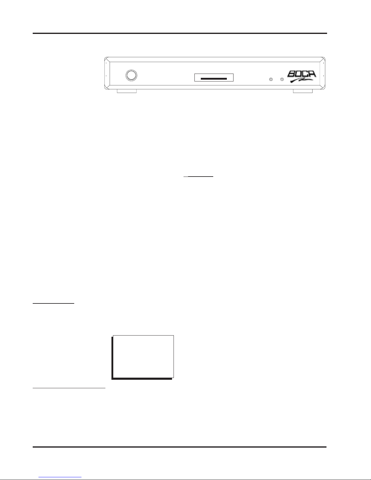
8Connectors and LEDs
FRONT VIEW
IR Receiver
Smart card Slot
Status LEDs
LED1—Power (GREEN)
LED2—Connect (RED)
REARVIEW:
Telephone jack (RJ-11).
Attach one
end of the supplied telephone cable to
this jack and the other end to your
phone outlet.
Printer parallel port (DB-25).
Allows
connection of printer to the unit, for
printing of WEB pages.
VGA Monitor port.
Use this port if you
are connecting the unit to a computer
monitor.
S-Video Output.
Use this port if your
television features an S-Video
connector. S-Video may provide
improved clarity of video display.
Composite video output.
Use the
video cable to connect this port to the
VIDEO-IN jack on your TV.
Right/Left audio channels.
Use the
audio cables to connect these ports to
the AUDIO-IN jacks on your TV.
Mouse.
Connect a PS/2 compatible
mouse.
Keyboard jack.
Connect a PS/2
compatible personal computer
keyboard.
AC Power connector
.Connect the AC
(110/220V) power cord here. Attach the
other end to your wall outlet. (MAKE
THIS CONNECTION LAST).
○○○○○○○○
○○○○○○
Reset (see
below)
DO NOT PRESS
THE RESET
BUTTON UNLESS
INSTRUCTED TO
DO SO BY YOUR
MANUFACTURER
SERVICE REP.
Connectors and LEDs
9
Connections
Connections
Connecting the Unit
Before you can access the Internet, you
need to connect the unit to:
A.Your television set (directly or through
your VCR), or VGA monitor.
B. A telephone wall jack.
C. An AC electrical outlet.
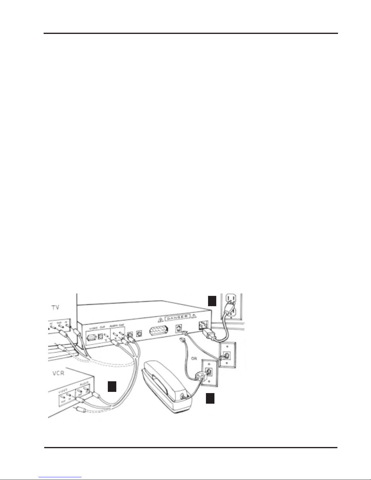
A common installation (TV or VCR with
audio jacks) is depicted below. More detail
is provided on page 12.Your connection
choice depends on how your TV is set up:
1. Does your TV have S-VIDEO, RCA-type
A/V (audio/video), or RF coaxial jacks?
2. Is your TV connected to a VCR?
IFYOU HAVE: THEN:
ATV/VCR without Audio/ Jacks... ...seepage 10
ATV with S-Video Jack... ...see page11
NOTE:Connection to S-VIDEO may offer improved video
display.To enhance audio performance, you may want to
integrate the unit into your home entertainment system.
A.Television and VCR
Connect one end of the supplied RCA-type A/V
cable to the BocaVision unit as identified and the
other end to the A/V IN jacks on your TV or VCR.
Make sure you match colors. If there is only one
audio jack, connect the white plugs only.
NOTE: If connecting through your VCR, connect
the VCR’s A/V OUT jacks to the TV’s A/V IN jacks.
If using a coaxial cable for this connection, connect
the coax OUT jack on your VCR to the coax VHF/
UHF jack on your TV, using a coaxial connector
cable (not supplied).You will need either a coaxial
cable, or an RCA-type A/V cable, but not both.
B. Telephone
Connect one end of the telephone cable to the
unit’s telephone jack. Connect the other end to the
telephone wall jack. For best results, connect the
unit to a telephone wall jack that you are not
currently using. If you have only one telephone wall
jack, use the supplied T-splitter so the unit and the
phone can share the same line.
C. Power
Connect the proper end of the AC power cord to the
unit’s power receptacle and then plug in (DO THIS
LAST).
A
B
C
*NOTE: For best results, connect
the unit to a telephone wall jack
that you are not currently using.
If you have only one telephone wall
jack, use the suppliedT-splitter so
the unit and the phone can share
the same line.When the unit is
active, an individual calling you will
receive a busy signal.If you have
CallWaiting, the unit will be
disconnected from the Internet and
you can take the call in the normal
manner.To reconnect to the
Internet following the phone call,
press GO BACK on your keyboard.
You will be re-connected to the
Internet and returned to the page
you were viewing when you
received the phone call.Call
Waiting can be disabled in the
Options Menu (see page 37).
*
10
○○○○○○○○
○○○○
○○○○
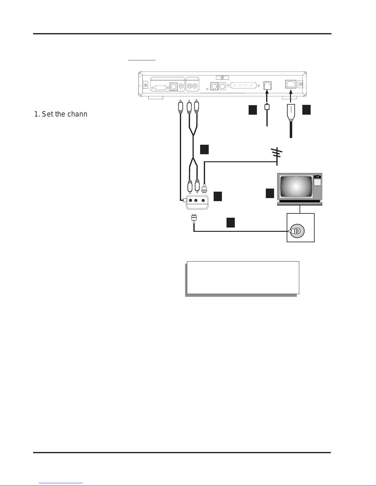
1. Set the channel switch on the RF
modulator (not supplied) (Radio
Shack cat.# 15-1283A) to VHF
channel 3 or 4, whichever is not
used or the least used in your
area.
2. Connect the RF modulator to the
Composite Video Output and
Right/Left audio channel jacks on
the unit.
3. Use an RF coaxial cable to
connect the TO TV jack on the
adapter to the ANTENNA IN jack
on the back of your TV.
You may need to disconnect the
antenna/cable from your TV to
make this connection. Connect the
antenna/cable to the ANTENNA IN
jack on the RF modulator.
4. Connect one end of the telephone
cable to the unit’s telephone jack.
Connect the other end to the
telephone wall jack.
5. Connect the proper end of the AC
power cord to the unit’s power
receptacle.
6. Set your TV to channel 3 or 4, as
selected in step 1 above.
VHF/UHF
1
4
AC
POWER
CORD
5
TV
Connecting to a TV or VCR without Audio/Video Jacks
Out toTV
2
3
6
RFModulator
RFcoaxial cable
TELEPHONE
CABLE
A/VCable
Video
Cable
Out toTV
Connections
RFcoaxial cable
NOTE: If your television or TV
remote has aTV/video button,
push this button.

11
Connections
NOTE: Connection to S-VIDEO may offer improved video
display.To enhance audio performance, you may want to
integrate the unit into your home entertainment system.
1. Use the supplied S-VIDEO cable to
connect the S-VIDEO OUT jack on the
unit to the S-VIDEO In jack on your TV.
2. Connect the Audio (right and left) jacks
on the unit to yourTV’s AUDIO IN jacks,
using the supplied audio cables.
NOTE: Do NOT connect the VIDEO
cable (usually yellow) to the VIDEO
jack when using the S-Video
connection.
3. Connect one end of the telephone
cable to the unit’s telephone jack.
Connect the other end to the telephone
wall jack.
4. Connect the proper end of the AC
power cord to the unit’s power
receptacle.
S-VIDEO
1
A/V
CABLE
2
AC POWER
CORD
4
REAR OF TV
VIDEO
L.
AUDIO
R.
AUDIO
S-VIDEO
Connecting to a TV with an S-VIDEO Jack
○○○○○○○○
○○○○○○○
TELEPHONE
CABLE
3
NOTE: If your television orTV
remote has a TV/video button,
push this button.
12
○○○○○○○○
○○○○
○○○○
Connections
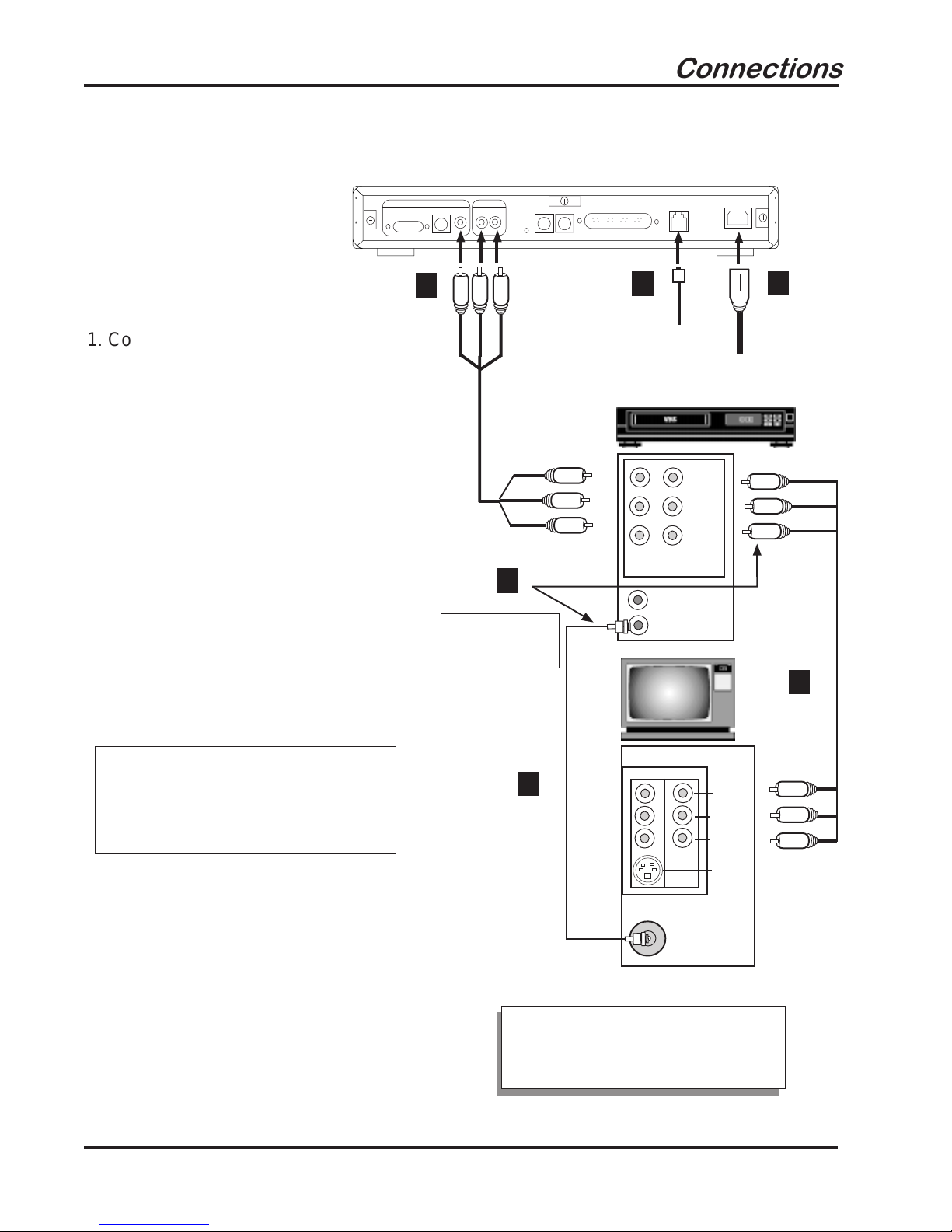
1. Connect one end of the supplied
RCA-type A/V cable to the unit as
identified and other end to the A/V
IN jacks on your VCR or TV. Make
sure you match colors. If there is
only one audio jack, connect the
white plugs.
2. Connect one end of the telephone
cable to the unit’s telephone jack.
Connect the other end to the
telephone wall jack.
3. Connect the proper end of the AC
power cord to the unit’s power
receptacle.
NOTE: For step 4, you need
either a coaxial cable (A), or an
RCA-type A/V cable (B),
but not
both.
4. If connecting through your VCR,
connect the VCR’s A/V OUT jacks
to the TV’s A/V IN jacks. If using a
coaxial cable for this connection,
connect the coax OUT jack on your
VCR to the coax VHF/UHF jack on
your TV, using a coaxial connector
cable (not supplied).
VHF/UHF
LINE-
IN LINE-
OUT
VIDEO
RIGHT
AUDIO
LEFT
AUDIO
A/V
CABLE
1
TEL.
CABLE
2
AC
POWER
CORD
3
VCR
TV
IN
OUT
EITHERCOAXIAL
OR RCA-TYPE
CABLE (not both)
4
IN
VIDEO 1VIDEO 2
S-VIDEO
VIDEO
L AUDIO
R AUDIO
Connecting to a TV or VCR with Audio/Video Jacks
Coax Cable
(not included)
RCA-type A/V
Cable (included)
A
B
NOTE: If your television or TV
remote has aTV/video button,
push this button.
13
Connections
Connecting a Wireless Keyboard
Your wireless keyboard installation is fast
and easy, as described below.
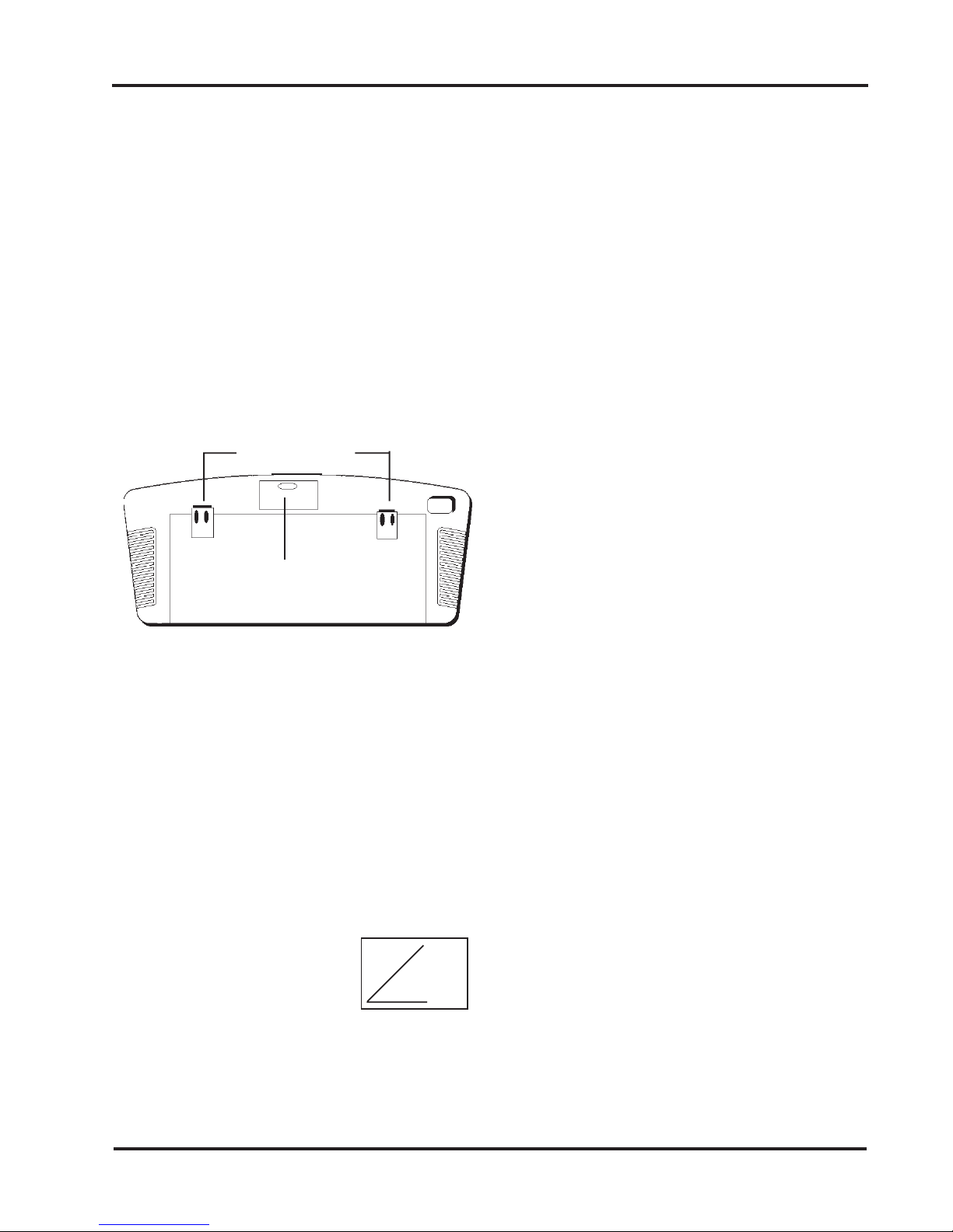
Inserting the batteries
1. Remove the battery compartment door.
2. Insert batteries (included) as shown in the
diagram inside the battery compartment.
3. Replace the battery compartment door.
Adjusting the Keyboard Height
To raise the keyboard, lift up the keyboard
legs until they snap into place.To lower the
keyboard, push each leg down until it fits
securely back into its cavity.
Pointing the Keyboard
The wireless keyboard should be used
within 25 feet of the unit. For best results it
should be pointed at no more than a 45o
angle.The keyboard works
on “line of sight”. If there are
obstructions between the
keyboard and the unit, or if
the keyboard is tilted at too severe an angle,
it may appear as if the keyboard isn’t
working.
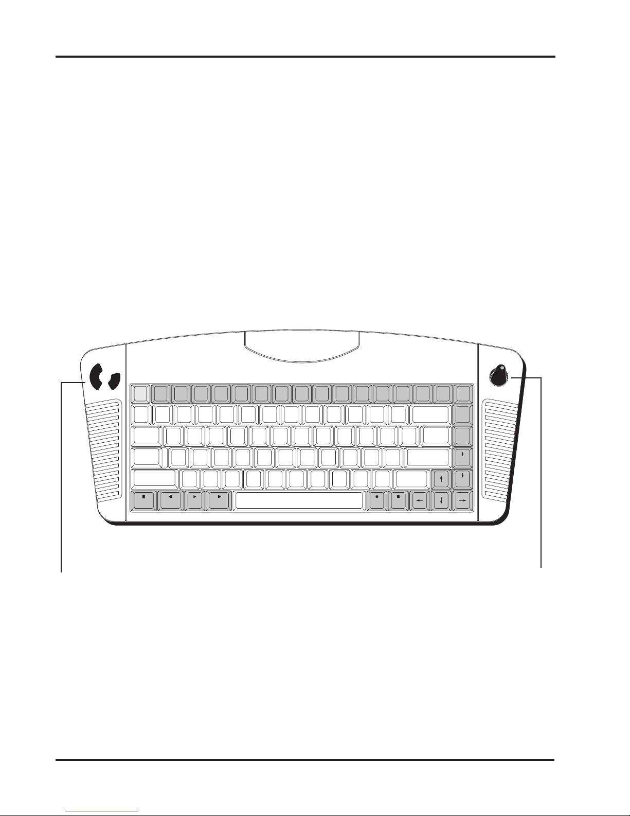
Keyboard Functions and Features
Arrows and ENTER / OK. Use the arrows to
highlight items on the menu screens, and when
surfing the web. Press ENTER / OK to select a
highlighted item.
ALT. In ICA-application sessions, performs
standard keyboard functions.
CLEAR/ESC. In ICA-application sessions,
performs standard keyboard functions.
CTRL. In ICA-application sessions, performs
standard keyboard functions.
FAV. Displays sites that are stored under
‘Favorites’ (when you are on-line).
FUNC. In combination with number keys, FUNC
provides the equivalent function of pressing F1
to F10 on a PS/2-compatible keyboard.
GO BACK. Returns you to the preceding frame,
web page, menu, or toolbar.
GO TO. Displays the URL Entry Toolbar so you
can type in an URL to “go to” that web page.
GUIDE. Reserved for future applications.
HOME. Takes you back to the URL specified
during setup.
INFO. Gives you web page details for a web
site.
(continued on next page)
Battery Compartment Door
Keyboard Legs
45oangle
14 Connections
MAIL. Reserved for future applications.
MENU. Brings up the Main menu, or the Toolbar
when you’re surfing the web.
PAGE UP and PAGE DOWN. Scroll up and
down through web content one page at a time.
POWER. Turns the unit on and turns it off
(standby mode).
PRINT. Displays the Print Options box.
RELOAD. Reloads the current web page. If you
are downloading a page, it stops the download
and loads the preceding page.
SAVE. Reserved for future applications.
SEARCH. Reserved for future applications.
SEND. Reserved for future applications.
Transport Keys (PAUSE, PLAY, STOP).
Controls Internet sound and movie player
functions. STOP also stops loading a web page
and stops printing. REV and FWD are reserved
for future applications.
WHO. Reserved for future applications.
~
`
BACK
SPACE
+
=
_
-
)
0
(
9
*
8
&
7
^
6
%
5
$
4
!
1@
2#
3
{
[
}
]
|
\
PAGE
UP
ENTER
"
'
:
;
CAPS
LOCK
SHIFT
<
,
>
.
?
/
SHIFT
REC
TAB
ESC CTRL ALT WHO PRINT RELOAD FAV SAVE GO TO SEARCH SEND MAIL HOME
PAGE
DOWN
STOP
MENU
GUIDE
PAUSE REV PLAY FWD
POWER
OK
CLEAR
FUNC GOBACK
INFO
QWERTYUIOP
LK
J
H
G
F
D
SA
ZXCVBNM
LEFT AND RIGHT MOUSE CONTROLS.
Use the left mouse control to select a
highlighted item on menu screen or
Internet. The right mouse control is
reserved for future applications.
POINTER. Use to highlight items on menu
screens and when you’re surfing the web
and when running software applications.
15
○○○○○○○○
○○○○
○○○○
Connections
Connecting a Standard (Wired) PS/2 Compatible Keyboard
Using a PS/2-Compatible Keyboard
You can connect a PS/2-type keyboard to
the unit. As with the wireless keyboard, you
will be able to type information and
responses into various text boxes which
appear on the WEB pages.
Connect the keyboard to the keyboard port
on the rear of the unit.The keyboard must
have a 6-pin DIN connector. Note that the
function keys on a personal computer
keyboard respond differently once it is
connected to the unit.
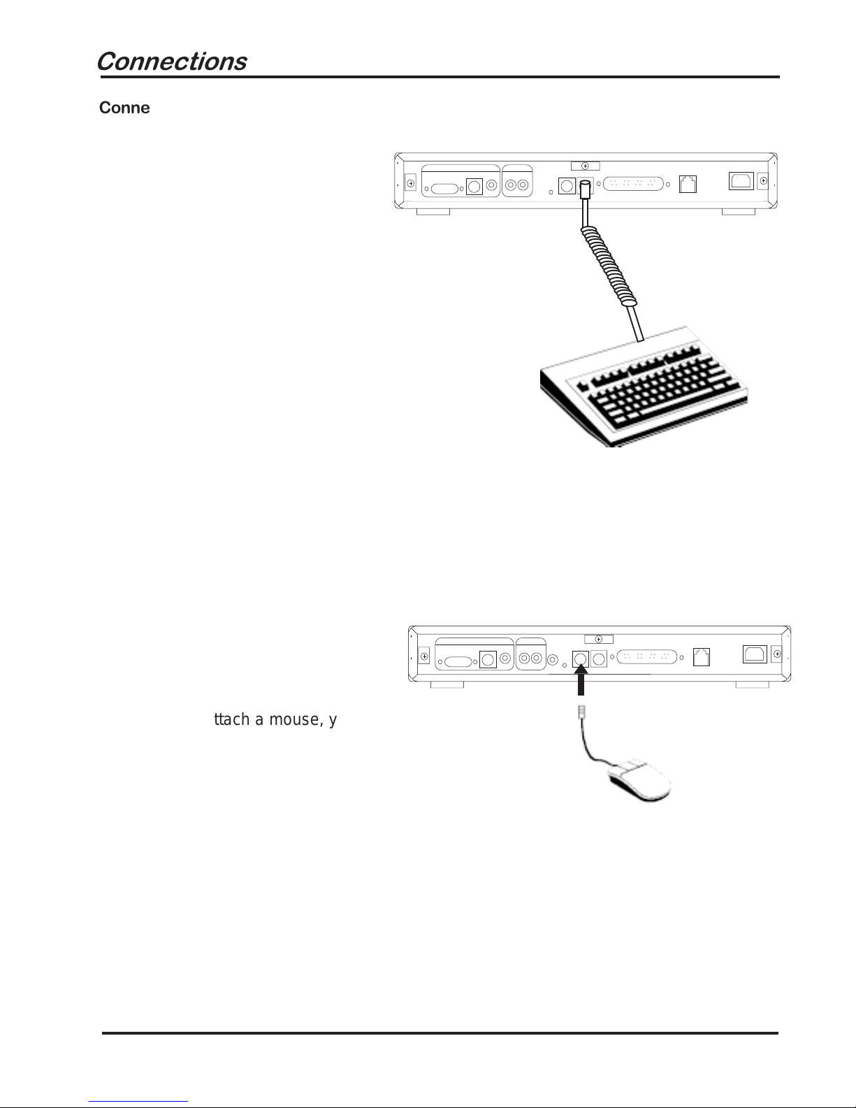
Connecting a Mouse
○○○○○○○○
○○○○
○○○○
If you wish to attach a mouse, you will need
a PS/2-type mouse (with DIN connector, not
9-pin serial connector).
16
Connecting a Printer to the DB-25
Parallel Port
You will need a 25-pin to 25-pin parallel
cable or the equivalent.
1. Connect the male end to the port
labelled PRINTER on the unit.
2. Connect the other end to your printer.
NOTE: See page 36 for instructions on
setting up your printer with the network
software.
See page 43 for a list of compatible
printers.
If your printer is not recognized when you
enter the code for the particular model, try
another code for the same brand, or try a
different brand.
Connections
○○○○○○○○
○○○○
○○○
○○○○○○○○
○○○○
○○○○
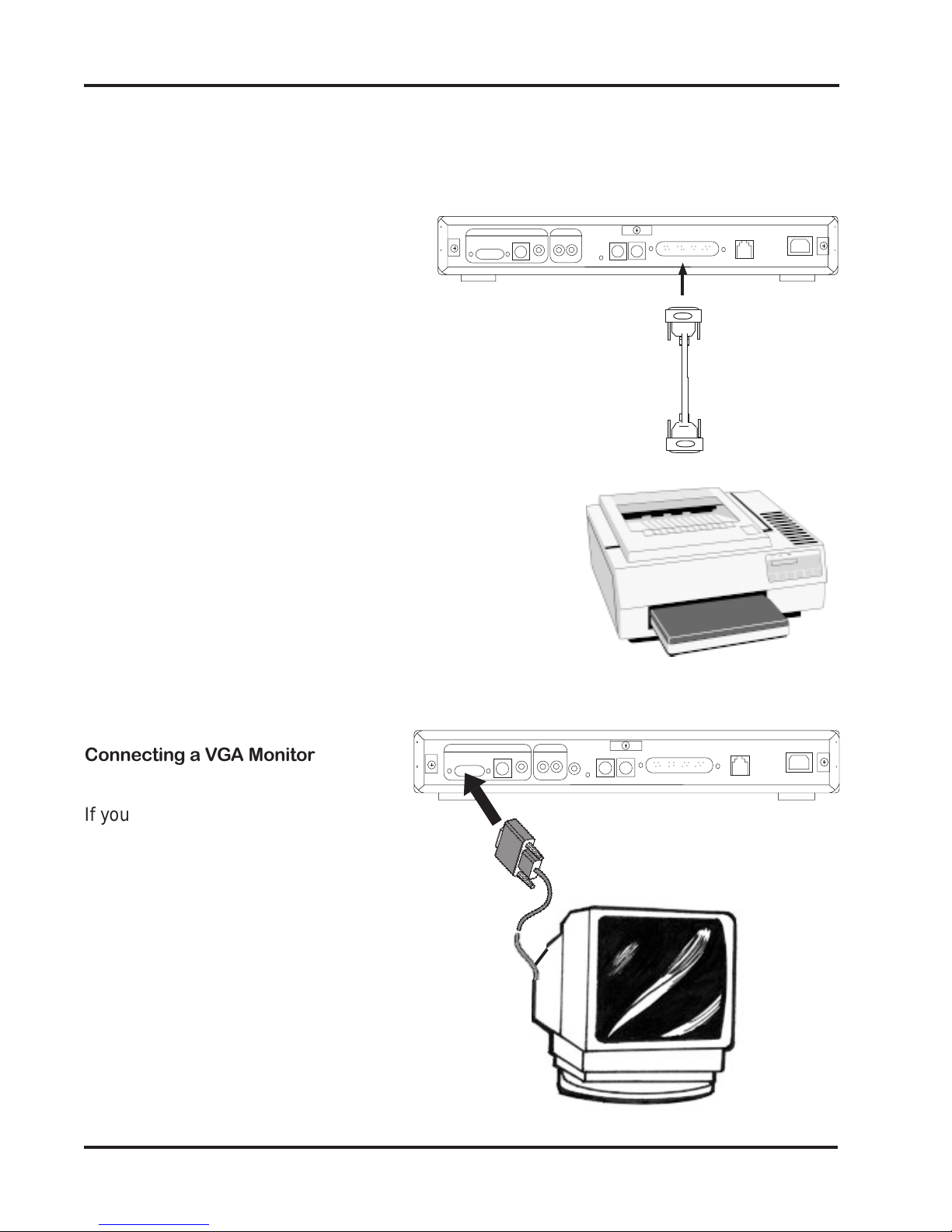
Connecting a VGA Monitor
If you wish to connect to aVGA monitor,
connect the VGA monitor cable to theVGA
port on the unit as shown.

17
Specifications
Connectors
• Internal 33.6Kbps Internet modem
• Smart card slot
• Parallel port allowing connection of printer
to the unit
• Keyboard and Mouse ports.
• VGA Port.
• S-Video output.
• RCA composite video output.
• RCA right/left audio channels.
• Telephone jack.
• Power connector.
Power Requirements
110-220V AC power supply
Accessories
• Audio/Video cables
• S-Video cable
• Phone cable
• Telephone line splitter
• AC power cord
• Wireless keyboard
• AA batteries
• Owner’s manual and EZ Setup guide
• Registration card
• Smart card
Dimensions
Width: 11.75” (29.85cm)
Length: 10.125” (25.72cm)
Height: 1.625” (3.18cm)
Weight: 2.50lbs. (1.13kg)
Miscellaneous Specifications
• Open ISP Architecture
• 8MB ROM
• 5MB DRAM
• ROM card slot
• Status LEDs:
Connect (RED);
Power (GREEN)
Specifications
18
Network Software
Introduction
This portion of the owner’s manual describes the interface for Internet access. Before you
begin, please have the following information readily available:
•Your Internet Service Provider (ISP) local phone number
•Your User name (logon name)
•Your password (logon password)
•Your ISP Home Page (URL)
•Your ISP Domain name
•Your ISP primary and secondary DNS numbers
On-Screen Display
The Network screen display is capable of 640 x 480 pixel resolution. All actual interface
elements reside within a safe area of 576 x 422 centered within the 640x480 screen.The
safe area is 5%, on the left and right edges, and 6%, at the top and bottom edges.
Color Palette
The display will support a maximum of 256 colors.
Screen Saver
If the unit detects no input from you for a period of five minutes, the screen saver image is
displayed. Any subsequent input removes the screen saver image. If there is no modem
activity for a period of ten minutes, the phone connection is dropped.
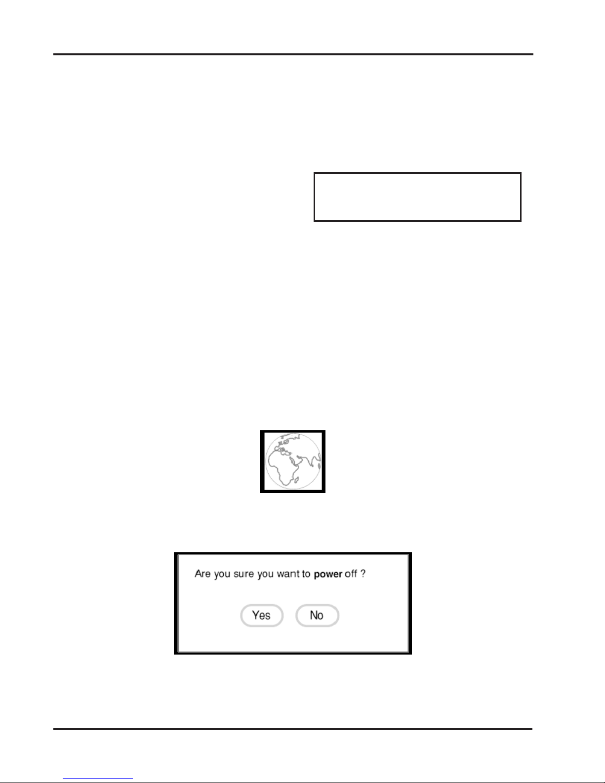
Power Off Request
If you press the power button on the wireless (IR) keyboard once more, the following
message appears:
Choose Yes to place the unit into standby mode.
Choose No to close the power off screen
Network Software
NOTE: If you are new to the Internet and do
not have an established relationship with an
Internet Service Provider (ISP), you will need
to contact one for the adjacent information.

19
Smart card
Before powering the unit on, make sure the smart card is properly
inserted (logo-side up) in the slot on the front.The card must be
properly inserted for the unit to work.
1. Locate the smart card included in the documentation package. It
should look similar to the illustration shown here.
2. Insert the card with the logo-
side up. Do not remove the
card during any session
unless instructed to do so.
3. Press the Power button on the wireless keyboard to
power on your unit. Or, press CTRL+ALT+DEL
on a standard PS/2 keyboard
Start-up Sequence
This section describes the
screens which are displayed
when you first begin to access
the Internet and attempt to
connect to your Internet Service
Provider (ISP).
Ready to Go Screen
This screen allows you to
access the Welcome screen
where you may set various
options, configure your smart
card, and connect to your ISP.
Welcome Screen
When you select the Welcome screen, the following appears.
Start-Up Sequence
NOTE: Actual
appearance of card
graphics may vary.
~
`
&
7
^
6
%
5
$
4
!
1@
2#
3
CAPS
LOCK
TAB
ESC CTRL ALT WHO PRINT RELOAD
POWER
CLEAR
FUNC
QWERTY
H
G
F
D
SA
Power Button

20
Choose Continue to return to the Ready to Go screen.
Choose Options to display the main options screen (as described in Options section,
pages 35-37).These options include settings for text size and scaling, setting up your
printer, adjusting the display, turning sounds on and off, and dialing and call-waiting
options.
Smart Card Screens
This section describes the smart card Setup screens that can appear when using a smart
card. From the Ready to Go screen, select Smart Card. If prompted for a PIN, enter
‘1234’ to continue.
Begin Setup
This screen allows you to set up for the first time or change ISP (Internet Service Provider)
and PIN (Personal Identification Number) information on your smart card.
Network Software
Table of contents
Other Boca Receiver manuals


