Bodensteckdosen Systemtechnik 6400E User manual
6400E
6522A
6523Q
BS Bodensteckdosen Systemtechnik GmbH | Dingerdisser Str. 36, 33699 Bielefeld
Die abgebildeten Zeichnungen
des Produkts dienen nur als
Referenz und können vom tat-
sächlichen Produkt abweichen.
The product drawings shown are
for reference only and may differ
from the actual product.
Montageanleitung
Assembly Instructions

2
Inhalt/Contents
Produktbeschreibung���������������������������� 3
Technische Daten����������������������������������� 4
Montageanleitung ���������������������������������� 5
Gebrauchshinweise ����������������������������� 13
Product description....................................3
Technical data..............................................4
Assembly instructions.............................. 9
Instructions for use..................................13

3
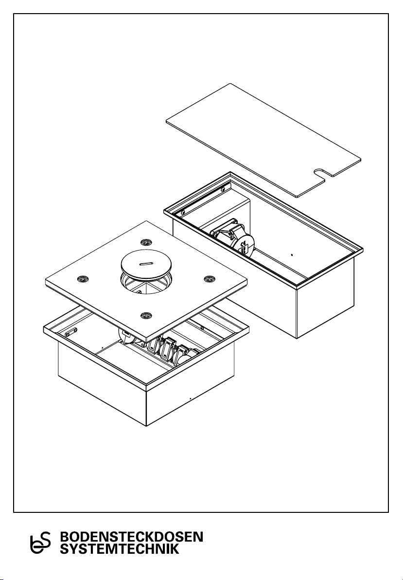
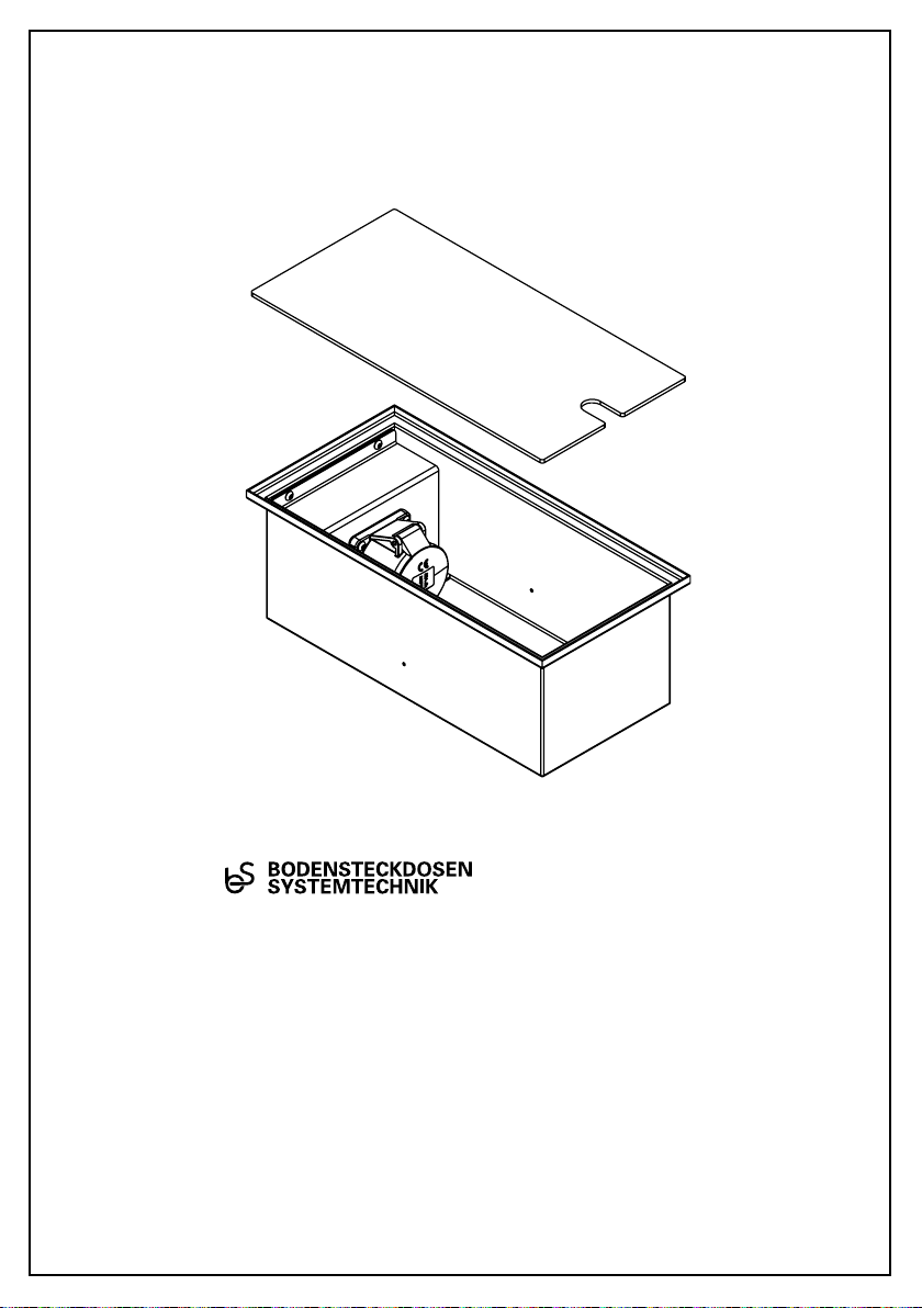
1
2
3
Bezeichnung/Designation:
Deckel/Lid
Geräteträger/Device carrier
Gehäuse/Housing
6400E/6522A /6523Q
Exemplarisch ist der Bodentank 6400E abge-
bildet. Das Montageprinzip gilt auch für den
Bodentank 6522A und den Bodentank 6523Q.
The floor box 6400E is shown as an example.
The assembly principle also applies to the floor
box 6522A and the floor box 6523Q.

4
Artikel-Nr. 6400E 6522A 6523Q
Einbaumaße 200x156x400 mm
(Bx H x T)
400x117x400 mm
(Bx H x T)
400x167x400 mm
(Bx H x T)
Zuleitungen 2x hinten, je Ø 25mm 4x hinten, je Ø 25mm 4x hinten, je Ø 25mm
Gewicht 5,6 kg 8,9 kg 15,7 kg
Schutzart IP10 IP65 IP65
Belastbarkeit Flächenlast max� 800kg Flächenlast max� 900 kg Flächenlast max� 900 kg
Item No 6400E 6522A 6523Q
Instl dim 200x156 x400 mm
(Wx H x D)
400x117x400mm
(Wx H x D)
400x167x 400 mm
(Wx H x D)
Supply line 2x back, each Ø 25mm 4x back, each Ø 25mm 4x back, each Ø 25mm
Weight 5,6 kg 8,9 kg 15,7 kg
Protection IP10 IP65 IP65
Load Area load max. 800kg Area load max. 900 kg Area load max. 900 kg
Technische Daten/Technical specifications
5
P
PB
L
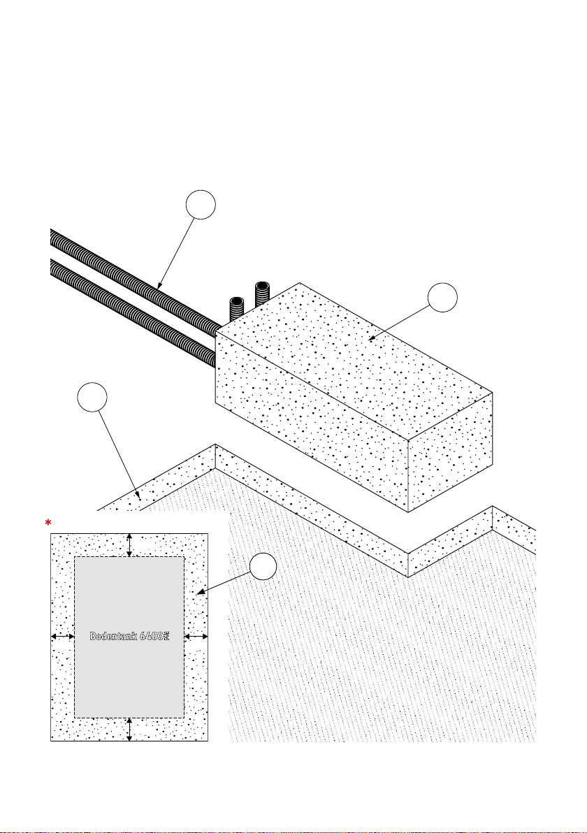
Montage im Estrich
Schritt 1 (Vorbereitungen)
Den Deckel abnehmen� Anschließend
den Geräteträger von dem Gehäuse
abmontieren�
Schritt 2
Vor dem Gießen des Estrichs (E) einen
Polystyrol-Block (PB)*, der in seiner äußeren
Abmessung umlaufend ca� 40mm größer
ist als der Bodentank, als Platzhalter auf die
ausgelegte Dämmschicht (P) kleben� Danach
die Leerrohre (L) verlegen und senkrecht
am Polystyrol-Block (PB) befestigen (zum
Beispiel mit Klebeband)�
40 mm 40 mm
40 mm
40 mm
Bodentank 6400E
PB
Ansicht von oben
Exemplarisch ist der Bodentank 6400E abgebildet.
Das Montageprinzip gilt auch für den Bodentank 6522A/6523Q.

6
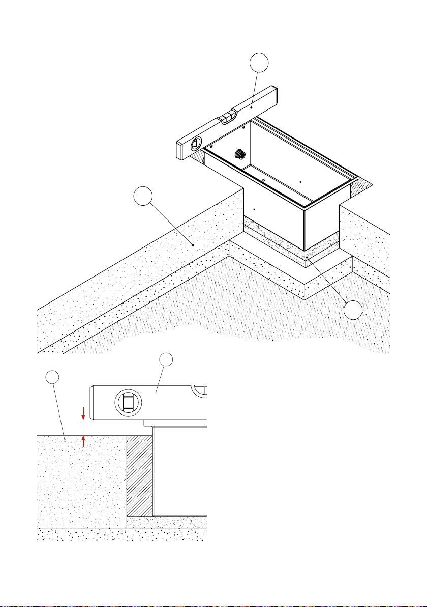
M
W
E
Schritt 3
Nach dem Gießen des Estrichs(E)
den Polystyrol-Block(PB)
aus dem Estrich(E) entfernen�
Das Gehäuse nun in die
entstandene Bodenaussparung
auf ein Mörtelbett*(M)
einsetzen und die Leerrohre(L)
in die Öffnungen des
Gehäuseseinführen�
W
E
t
*Achtung!
Die Höhe des Mörtelbetts(M) muss so
vermessen werden, dass der Abstand ’t’
zwischen Wasserwaage (W) und
Estrich (E) so groß ist, wie die spätere
Belagsstärke� Zudem muss das Mörtelbett
(M) für die entsprechende Belastung des
Bodentanks ausgelegt sein�

7
M
W
Schritt 4
Das Gehäuseabdichten� (Tipp: die
Gehäuseöffnung beispielsweise mit
Pappe abdecken, nicht abgebildet.)
Die Aussparung um das Gehäusenun
mit Mörtel(M) auffüllen� Die Position
des Gehäusesvor dem Aushärten des
Mörtels(M) mit der Wasserwaage (W)
überprüfen!

8
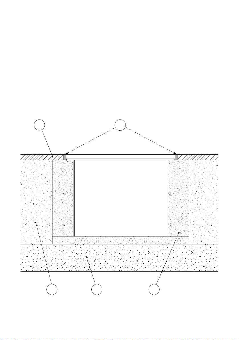
Schritt 5
Nach dem Aushärten die Geräte anschließen,
den Geräteträger wieder in das Gehäuse
einschrauben und den Deckel einsetzen�
Schließlich den Bodenbelag (B) im Raum
verlegen und eine Flexfuge (FF) aus Silikon
einsetzen� Der Bodentank ist nun erfolgreich
eingebaut� (Siehe Querschnitt unten.)
M
P
E
BFF

9
P
PB
L
Installation in a screed floor
Step 1 (Preparations)
Remove the lid� Then remove the device
carrierfrom the housing�
Step 2
Before pouring the screed(E), a polystyrene
block(PB) with a circumference of approx�
40 mm larger than the floor tank in its outer
dimension*must be glued to the insulation
layer(P) as a placeholder� Then lay the
conduits(L) and fix them (e�g� with adhesive
tape) vertically to the polystyrene block
(PB)�
40 mm 40 mm
40 mm
40 mm
floor tank 6400E
PB
View from above
The floor box 6400E is shown as an example. The installation
principle also applies to the floor box 6522A and 6523Q.
10
M
W
E
W
E
t
Step 3
Remove the polystyrene block(PB)
after pouring the screed(E)� Now insert
the housinginto the resulting floor
recess on a mortar bed*(M) and install
the conduits(L) into the openings of
the housing�
*Attention!
The height of the mortar bed(M) must be
measured so that the distance ’t’ between
the spirit level(W) and the screed(E) is
as large as the subsequent covering thick-
ness� In addition, the mortar bed(M) must
be designed for the corresponding load
on the floor tank�

11
M
W
Step 4
Seal the housing� (Tip: cover the box
opening, for example, with cardboard,
not shown.) Now fill the recess
around the housingwith mortar (M)�
Check the position of the housing
with the spirit level(W) before curing
the mortar(M)!
12
M
P
E
BFF
Step 5
After hardening, connect the devices, screw the
device carrierback into the housing and
insert the lid� Finally, lay the floor covering(B)
in the room and insert a flexible joint(FF) made
of silicone� The floor tank is now successfully
installed� (See cross section below.)

13
Um eine anhaltende Funktion der Bodensteckdose
zu gewährleisten sind folgende Hinweise zu
beachten:
• Anschluss, Reparatur oder Instandhaltung sind
von einer ausgebildeten Fachkraft durchzuführen�
Während des Einbaus und der Inbetriebnahme
sind Handschuhe zu tragen�
• Für die Montage der Bodensteckdose muss ein
fester Untergrund (z�B� Estrich, Beton) vorhanden
sein�
• Bei der Montage auf einem unbefestigten Unter-
grund ist die Bodensteckdose weder begehbar noch
befahrbar�
• Die Anschlussleitung muss einen Querschnitt
entsprechend der Vorschrift des VDE aufweisen�
• Falls Kabelverschraubungen verwendet werden,
sollte diese für den entsprechenden Kabelquer-
schnitt geeignet sein�
• Für die 6523Q: Bei der Verwendung des Tubus
muss dieser immer vollständig in die Dichtung
greifen um eine Wasserdichtigkeit zu gewähr-
leisten�
• Pflegehinweis: Das Produkt ist für die Nasspflege
geeignet� Dazu zählt auch das Verwenden von
Nasskehrmaschinen, bei denen der Bodenbelag
kurzzeitig durchnässt wird� Zudem dürfen für
die Reini-gung keine säure-, chloridhaltige oder
alkalische Mittel verwendet werden�
• Für einen einwandfreien Betrieb sind die Dich-
tungen regelmäßig vom Schmutz zu befreien und
auf einen einwandfreien Zustand zu überprüfen�
• Die angegebene Schutzart kann nur im einwand-
freien, geschlossenen und ungenutzten Zustand
der Bodensteckdose gewährleistet werden�
• Bei mechanischen Schäden oder anderen Mängeln
(technisch/elektrisch) darf das Produkt nicht in
Betrieb genommen werden�
• Das Produkt ist unter Beachtung der nationalen
Vorschriften zu entsorgen�
Irrtümer und technische Änderungen
vorbehalten.
In order to ensure a lasting function of the
floor socket, the following instructions must
be observed:
• Connection, repair or maintenance must be carried
out by a trained specialist. During installation and
commissioning gloves must be worn.
• For the installation of the floor socket, a solid
surface (for example screed, concrete) must be
present.
• When installed on an unpaved surface, the floor
socket cannot be walked on or driven on.
• The connecting cable must have a cross-section
in accordance with the VDE regulation.
• If cable glands are used, they should be suitable
for the corresponding cable cross-section.
• For the 6523 Q: When using the tube, it must always
fully grip the seal to ensure water tightness.
• Care instructions: The product is suitable for wet
care. This also includes the use of wet sweepers,
where the floor covering is soaked for a short time.
In addition, no acid-, chloride containing or alkaline
products may be used for cleaning.
• For trouble-free operation, the seals must be
regularly cleaned of dirt and checked to ensure
that they are in perfect condition.
• The specified degree of protection can only
be guaranteed in the perfect, closed and unused
condition of the ground socket.
• In the case of mechanical damage or other defects
(technical/electrical), it is not allowed to put the
product into operation.
• The product is in compliance with the national
regulations to dispose.
Errors and technical changes reserved.
Gebrauchshinweise/Instructions for use
Irrtümer und technische Änderungen vorbehalten.
Subject to errors and technical changes.
© by BS Bodensteckdosen Systemtechnik GmbH
BS Bodensteckdosen
Systemtechnik GmbH
Dingerdisser Str� 36
33699 Bielefeld, Germany
Tel +49 521 9892780
Fax+49 521 989278-30
info@bodensteckdosen�com
www�bodensteckdosen�com
This manual suits for next models
2
Other Bodensteckdosen Systemtechnik Cable Box manuals

Bodensteckdosen Systemtechnik
Bodensteckdosen Systemtechnik 20er A/Q Series User manual

Bodensteckdosen Systemtechnik
Bodensteckdosen Systemtechnik 56 E-Series User manual

Bodensteckdosen Systemtechnik
Bodensteckdosen Systemtechnik 8804B User manual

Bodensteckdosen Systemtechnik
Bodensteckdosen Systemtechnik 8808B User manual


