Bodensteckdosen Systemtechnik 8808B User manual

Bedienungsanleitung
Instruction Manual
8808B/8810B

2
Inhalt/Contents
Produktbeschreibung ���������������������������� 3
Technische Daten������������������������������������ 4
Montageanleitung����������������������������������� 5
Gebrauchshinweise������������������������������ 13
Product description ������������������������������������ 3
Technical data����������������������������������������������� 4
Assembly instructions ������������������������������� 9
Instructions for use ���������������������������������� 13

3
1
3
2
4
8808B/8810B
Exemplarisch ist die Bodensteckdose 8808B
abgebildet. Das Montageprinzip gilt auch für
die Bodensteckdose 8810B.
The 8808B floor socket is shown as an
example� The installation principle applies
to the floor socket 8810B, too�
Bezeichnung/Designation:
Deckel/Lid
Steckdose/Socket
Geräteträger/Device carrier
Gehäuse/Box

4
Technische Daten/Technical specifications
Art.-Nr.
Item No 8808B 8810B
Einbaumaße
Instl dim 240x240x 64 mm 300 x 300 x 62 mm
Zuleitungen
Supply line
8x seitlich/lateral
Ø 25mm
10x seitlich/lateral
Ø 25mm
Nivellierbar
Height adj 5mm 5mm
Schutzart
Protection IP20 IP20
Belastbarkeit
Load
Flächenlast/Area load
max� 200kg
Flächenlast/Area load
max� 200kg

5
Montageanleitung
PB
L
P
Schritt 1 (Vorbereitungen)
Den Deckel abnehmen (siehe links,
Umschlagseite 3)� Anschließend den
Geräteträger von dem Gehäuse
abmontieren�
Schritt 2
Vor dem Gießen des Estrichs einen
Polystyrol-Block(PB), der in seiner äußeren
Abmessung umlaufend ca� 40mm größer
ist als die Dose*, als Platzhalter auf die
ausgelegte Dämmschicht (P) kleben� Danach
die Leerrohre (L) verlegen und senkrecht
am Polystyrol-Block (PB) befestigen (zum
Beispiel mit Klebeband)�
40 mm 40 mm
40 mm
40 mm
Bodensteckdose
Ansicht von oben
PB

6
W
M
P
E
Schritt 3
Nach dem Gießen des Estrichs den
Polystyrol-Block aus dem Estrich
entfernen� Das Gehäuse nun in
die enstandene Bodenaussparung
auf ein Mörtelbett*(M) einsetzen
und die Leerrohre in die Öffnungen
des Gehäuseseinführen�
*Achtung!
Die Höhe des Mörtelbetts (M) muss so
vermessen werden, dass die Wasserwaage
(W) und der Estrich (E) bündig/fluchtend
sind! Zudem muss das Mörtelbett für
die entsprechende Belastung der Boden-
steckdose ausgelegt sein�
W
E
MP

7
W
M
P
E
Schritt 4
Das Gehäuse
abdichten! (Tipp: die
Gehäuseöffnung oben beispielsweise mit
Pappe o.ä. abdecken, wie abgebildet.)
Die Aussparung um das Gehäusenun
mit Mörtel (M) auffüllen� Die Position des
Gehäuses vor dem Aushärten des Mörtels
mit einer Wasserwaage (W) überprüfen!

8
Schritt 5
Nach dem Aushärten des Mörtels die
Steckdosenanschließen und den
Geräteträgerwieder in das Gehäuse
einschrauben� Danach den Deckel
mit Belag (B) bekleben und einsetzen�
Den restlichen Belag(B) im Raum verlegen�
Die Bodensteckdose ist nun erfolgreich
eingebaut� (Siehe Querschnitt unten.)
E
P
M
B

9
Assembly Instructions
Step 1 (Preparations)
Remove the lid� Then remove the device
carrierfrom the box � (See page U3)�
Step 2
Before pouring the screed, a polystyrene
block (PB) with a circumference of approx�
40 mm larger than the box in its outer
dimension*must be glued to the insulation
layer (P) as a placeholder� Then lay the
conduits (L) and fix them (e.g. with adhesive
tape) vertically to the polystyrene block (PB)�
PB
L
P
40 mm40 mm
Floor socket
40 mm
40 mm
View from above
PB

10
W
M
P
E
Step 3
Remove the polystyrene block (PB) after
pouring the screed� Now insert the
housing into the resulting floor recess
on a mortar bed* (M) and install the
conduits into the openings
of the housing�
W
E
MP
*Attention!
The height of the mortar bed (M) must
be measured so that the spirit level (W)
and screed (E) are flush/aligned! In addition,
the mortar bed must be designed for the
corresponding load on the floor socket�

11
Step 4
Seal the box
!(Tip: Cover the box opening,
for example with cardboard, as shown.)
Now fill the recess around the boxwith
mortar (M)� Check the position of the box
before curing the mortar!
W
M
P
E

12
Step 5
After curing, connect the sockets , screw
the device carrierback into the housing �
Glue floor cover into the lid and insert the lid�
Lay the remaining covering (B) in the room�
The floor socket is now successfully installed�
(See cross section below.)
E
P
M
B

13
Um eine anhaltende Funktion der Bodensteckdose
zu gewährleisten sind folgende Hinweise zu
beachten:
• Anschluss, Reparatur oder Instandhaltung sind
von einer ausgebildeten Fachkraft durchzuführen�
Während des Einbaus und der Inbetriebnahme sind
Handschuhe zu tragen�
• Für die Montage der Bodensteckdose muss
ein fester Untergrund (z�B� Estrich, Beton, etc�)
vorhanden sein�
• Bei der Montage auf einem unbefestigten
Untergrund ist die Bodensteckdose nicht begehbar�
• Die Anschlussleitung muss einen Querschnitt
entsprechend der Vorschrift des VDE aufweisen�
• Falls Kabelverschraubungen verwendet werden,
sollte diese für den entsprechenden Kabel-
querschnitt geeignet sein und eine entsprechende
Schutzart aufweisen�
• Bei Verwendung der Nivellierschrauben zur Höhen-
korrektur des Deckels ist die Bodensteckdose nur
begehbar�
• Pflegehinweis: Das Produkt ist für die Trocken-
pflege geeignet (es werden flüssigkeitslose oder
flüssigkeitsarme (nebelfeuchte) Verfahren zur
Reinigung verwendet)� Zudem dürfen für die
Reinigung keine säurehaltigen, chloridhaltigen oder
alkalische Mittel verwendet werden�
• Trotz Qualitätsprüfung kann es im Fertigungs-
prozess zu scharfen Kanten oder Ecken an Gehäuse,
Deckel oder anderen Bauteilen kommen�
• Bei mechanischen Schäden oder anderen Mängeln
(technisch/elektrisch) darf das Produkt nicht in
Betrieb genommen werden�
• Das Produkt ist unter Beachtung der nationalen
Vorschriften zu entsorgen�
Irrtümer und technische Änderungen
vorbehalten.
In order to ensure a lasting function of the
floor socket, the following instructions must
be observed:
• Connection, repair or maintenance must be carried
out by a trained specialist� During installation and
commissioning gloves must be worn�
• For the installation of the floor socket, a solid
surface (for example screed, concrete) must be
present�
• When installing on an unpaved surface, the floor
socket is not walkable�
• The connecting cable must have a cross-section
in accordance with the VDE regulation�
• If cable glands are used, they should be suitable for
the corresponding cable cross-section and have an
appropriate degree of protection�
• When using the leveling screws for height correcting
the lid, the floor socket is only walkable�
• Care instructions: The product is suitable for dry
care (liquid-free or low-liquid (mist-moist) cleaning
methods are used)� In addition, no acid-, chloride-
containing or alkaline products may be used for
cleaning�
• Despite quality inspection, sharp edges or corners
on housings, lids, or other components may occur
during the manufacturing process�
• In the case of mechanical damage or other defects
(technical/electrical), it is not allowed to put the
product into operation�
• The product is in compliance with the national
regulations to dispose�
Errors and technical changes reserved.
Gebrauchshinweise/Instructions for use

© by BS Bodensteckdosen Systemtechnik GmbH
BS Bodensteckdosen
Systemtechnik GmbH
Oldermanns Hof 2a
33719 Bielefeld, Germany
Tel +49 521 260109-90
Fax+49 521260109-99
info@bodensteckdosen�com
www�bodensteckdosen�com
Irrtümer und technische Änderungen vorbehalten.
Subject to errors and technical changes.
This manual suits for next models
1
Table of contents
Languages:
Other Bodensteckdosen Systemtechnik Cable Box manuals

Bodensteckdosen Systemtechnik
Bodensteckdosen Systemtechnik 6400E User manual
Bodensteckdosen Systemtechnik
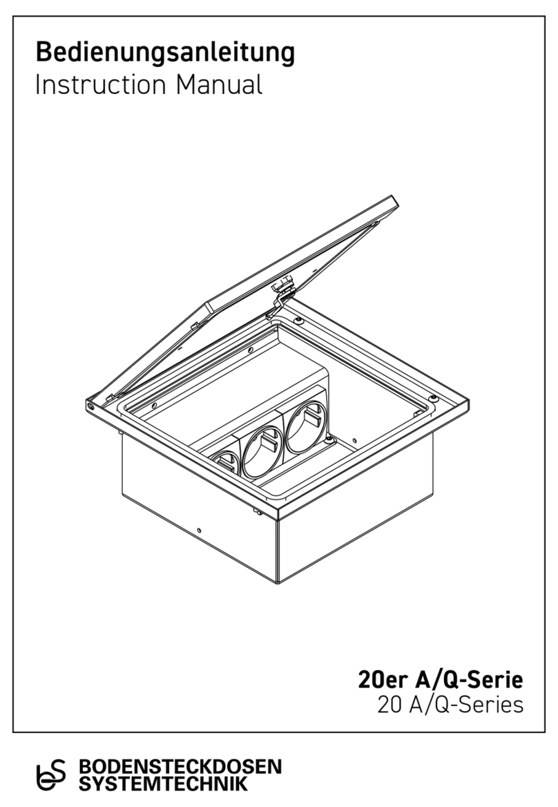
Bodensteckdosen Systemtechnik 20er A/Q Series User manual

Bodensteckdosen Systemtechnik
Bodensteckdosen Systemtechnik 8804B User manual

Bodensteckdosen Systemtechnik
Bodensteckdosen Systemtechnik 56 E-Series User manual
Popular Cable Box manuals by other brands
enz
enz ricoo Z0101 Series Assembly instructions
OBO Bettermann
OBO Bettermann UDHome2 V SA Mounting instructions

Bebob
Bebob COCO-FX9-VMICRO user manual
Tripp Lite
Tripp Lite SR13 Management guide
Clearfield
Clearfield FieldShield YOURx-TAP installation manual
American Dynamics
American Dynamics RJ855AP installation guide
