Bodine BSL310LPST User manual
SAVE THESE INSTRUCTIONS
THIS PRODUCT CONTAINS A RECHARGEABLE NICKEL-CADMIUM BATTERY.
THE BATTERY MUST BE RECYCLED OR DISPOSED OF PROPERLY.
Bodine © 2018 Signify Holding. All rights reserved.
236 Mt. Pleasant Rd. • Collierville, TN USA 38017-2752 • Tech Support 888-263-4638 • Fax 901-853-5009 • www.bodine.com
442294629632
BSL310LPST
03/07/19
Ni - Cd
CLASS 2 OUTPUT
Self-Testing Emergency LED Driver
READ AND FOLLOW ALL SAFETY INSTRUCTIONS
! IMPORTANT SAFEGUARDS ! WHEN USING ELECTRICAL EQUIPMENT, BASIC
SAFETY PRECAUTIONS SHOULD ALWAYS BE
FOLLOWED, INCLUDING THE FOLLOWING:
1. To prevent voltage from being present on yellow & yellow/black output leads prior to installation, converter
connector must be open. Do not join converter connector until installation is complete and AC power is
supplied to the emergency driver.
2. This product is for use with an emergency LED lighting load and supplies nominaly 10.0 W of power, with
a voltage of 15-52 VDC in emergency mode for a minimum of
90 minutes, in compliance with NFPA-101 and NEC 700.12.
3. Make sure all connections are in accordance with the National Electrical Code or Canadian Electrical Code and
any local regulations.
4. To reduce the risk of electric shock, disconnect both normal and emergency power supplies and converter
connector of the emergency driver before servicing.
5. This emergency driver is suitable for both factory or field installation. For field installation, please see the
instructions on page 2.
6. This product is suitable for use in damp locations where the ambient temperature is 0ºC minimum, +55ºC
maximum. Product is also suitable for installation in sealed and gasketed fixtures. Product is not suitable
for heated air outlets and wet or hazardous locations. Maximum allowable case temp is 65ºC. See Page 4
for Tcase measurement location.
7. An unswitched AC power source is required (120-277 VAC, 50/60 Hz).
8. Do not install near gas or electric heaters.
9. Do not attempt to service the battery. A sealed, no-maintenance battery is used that is not field
replaceable. Contact the manufacturer for information on service.
10. The use of accessory equipment not recommended by the manufacturer may cause an unsafe condition.
11. Do not use this product for other than intended use.
12. Servicing should be performed by qualified service personnel.
13. Equipment should be mounted in locations and at heights where it will not be subjected to tampering by
unauthorized personnel.
14. For Canadian application the output terminals should be in compliance with the accessibility requirement of
the Canadian Electric Code.
15. This device complies with part 15 of the FCC Rules. Operation is subject to the following two conditions: (1)
this device may not cause harmful interference, and (2) this device must accept any interference that may
cause undesired operation.
16. This product must be grounded. See the wiring diagrams for details.
Installation Instructions

INSTALLATION
2
STEP #1 INSTALLING THE EMERGENCY DRIVER
> Disconnect AC power from the LED luminaire.
> Mount the emergency LED driver by the mounting tabs using the supplied screws. The luminaire’s installation
instructions may provide guidance on the recommended mounting location.
>The emergency driver may be remote mounted from the luminaire. If used in conjunction with an AC driver, this distance
is up to half the distance the AC driver manufacturer recommends remote mounting the AC driver from the LED Load. If
used without an AC driver, consult factory for remote mounting distances.
> Mounting Height: This product meets or exceeds the NFPA minimum light requirements with all loads, down to the
smallest rated lamp load, at heights up to 7.17ft (2.2m). Many factors influence emergency illumination levels, such as
the lamp load selected, luminare design, and environmental factors therefore end use verification is necessary. For field
installations, when the attached luminaire is mounted at heights greater than 7.17ft (2.2m), the level of illumination
must be measured in the end application to ensure the requirements of NFPA 101 and local codes are satisfied.
> Remote Mounting: The emergency LED driver may be remote mounted from the luminaire. If used in conjunction with
an AC driver the allowed distance is up to half the distance the AC driver manufacturer recommends remote mounting
the AC driver from the LED load. If used without an AC driver, and remote mounting more than 5 feet from the luminaire,
please consult the factory to determine the necessary wire gauge. CAUTION: Remote mounting can result in reduced
power output.
2
NOTE: Make sure the necessary branch circuit wiring is available. An unswitched source of power is
required. The emergency driver must be fed from the same branch circuit as the AC driver.
Lumens In Emergency Mode = Lumens per Watt of Fixture * Output Power of Chosen Product
________________(Lumens)_ = __________________(lm/W)_* ________10______(W)_
CAUTION: DO NOT JOIN CONVERTER CONNECTOR UNTIL INSTALLATION IS COMPLETE AND AC POWER IS
SUPPLIED TO THE EMERGENCY DRIVER.
1. Ensure the LED load’s rated power is greater than or equal to the power output of this emergency LED driver. This is to
ensure that this emergency product will not produce more power than the LED load can handle, thus ensuring that the
LED load will not be damaged when the system is in the emergency mode.
2. Verify that the forward voltage of the luminaire’s LED array is within the limits of this emergency LED driver. The forward
voltage of the LED array is commonly designated as Vf and should be found on the luminaire markings, in the luminaire
specifications, or imprinted directly on the LED arrays. If multiple LED arrays are to be driven, verify that the total
forward voltage is within the limits of this product. Using a voltage meter, it may be possible to directly measure the
voltage across the LED arrays when operating from the AC driver.
3. Ensure the output current of the LED driver does not exceed 2.5 Amps. This is the current into the blue wire.
4. Ensure there will be sufficient light output in the end application. Estimate the egress lighting illumination levels by
doing the following:
a. Find the efficacy of the LED load. This can be given by the luminaire manufacture. This number will be given in
lumens per watt (lm/w). It is the installer’s responsibility to validate the luminaire manufacturer’s efficacy data.
This can be accomplished by direct measurement, by review of independent 3rd party test data (UL, ETL, etc.),
accessing a public database of 3rd party data (such as Design Lights Consortium, www.designlights.org), or other
comparable means.
b. Lumens can be calculated by multiplying the output power of the emergency LED driver by the efficacy of the LED
load. In many cases the actual lumen output in emergency mode will be greater than this calculation gives, however
it will provide a good estimate for beginning the lighting design of the system.
C. Using the results of this calculation and industry standard lighting design tools, calculate the anticipated
illumination levels in the path of egress.
This product is suitable for field installation with suitable LED loads including LED luminaires, DC voltage driven LED
replacements for fluorescent lamps and others. There are four (4) checks to determine if your luminaire is eligible for field
installation.
NOTE: This product has been designed to reliably interface with a wide selection of LED loads and is electrically compatible
with every simple LED array that meets criteria 1 and 2 above. However, compatibility cannot be guaranteed with all current
and future LED systems. Compatibility testing of the end-use system is suggested. Please contact the factory with any
questions.
Installation of this emergency LED driver will vary based on the luminaire type, however, generally
follow these steps:
NOTE: After installation, it will be necessary to measure the egress lighting illumination levels to ensure it complies with
national, state, and local code requirements.
STEP #3 WIRING THE EMERGENCY BALLAST
> Select the appropriate wiring diagram to connect the emergency driver to the AC driver and LED load.
Make sure all connections are in accordance with the National Electrical Code and any local regulations.
> After installation is complete, supply AC power to the emergency driver and join the converter connector.
> At this point, power should be connected to both the AC driver and the emergency driver, and the Charging
Indicator Light should illuminate indicating the battery is charging.
> A short-term discharge test may be conducted after the emergency driver has been charged for one hour. Charge
for 24 hours before conducting a long-term discharge test. Refer to OPERATION.
> In a readily visible location, attach the label "CAUTION - This Unit Has More Than One Power Connection Point.
To Reduce The Risk Of Electric Shock, Disconnect Both The Branch Circuit-Breakers Or Fuses And Emergency
Power Supplies Before Servicing."
PUSH TO TEST
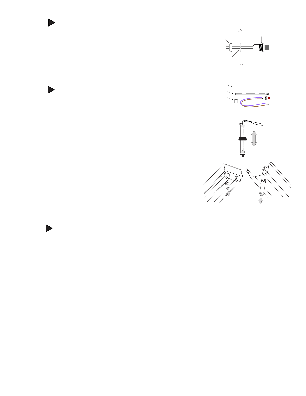
INSTALLING THE 2W-ITS ON A BALLAST CHANNEL COVER
> Drill or punch a 7/8 inch hole in the ballast channel cover. Insert the large
flanged bushing included with the parts kit. Insert the plastic tube into the
large flanged bushing. Slide the 2W-ITS tube up or down to adjust the height
and visibility of the charging indicator light.
> Slide the plastic tube up or down to adjust the height and visibility of the
charging indicator light. If the tube is too long, cut the plastic tubing to
necessary length.
> After cutting the tube to the proper length, assemble the 2W-ITS.
To assemble the 2W-ITS Assembly:
• Feed the 2W-ITS leads through the plastic tubing.
• Insert the white bushing in the opposite end of tube from the 2W-ITS
body.
• Pull switch leads and use provided tie wrap to secure leads snug against
white bushing.
• Unscrew hex nut to apply tension to leads.
> Wire the test switch per wiring diagrams provided on these instructions.
> If wired correctly, the 2W-ITS indicator light should be ON when AC power is
supplied to the fixture, and the convertor connector is closed indicating that
the emergency inverter battery is charging. After installing, mark with the
"PUSH TO TEST" and "CHARGING INDICATOR LIGHT" labels.
STEP #2b
PUSH TO TEST
Plastic Tube
2 Wire Illuminated Test Switch
Tie Wrap
White
Bushing
2W-ITS
Assembly
Components
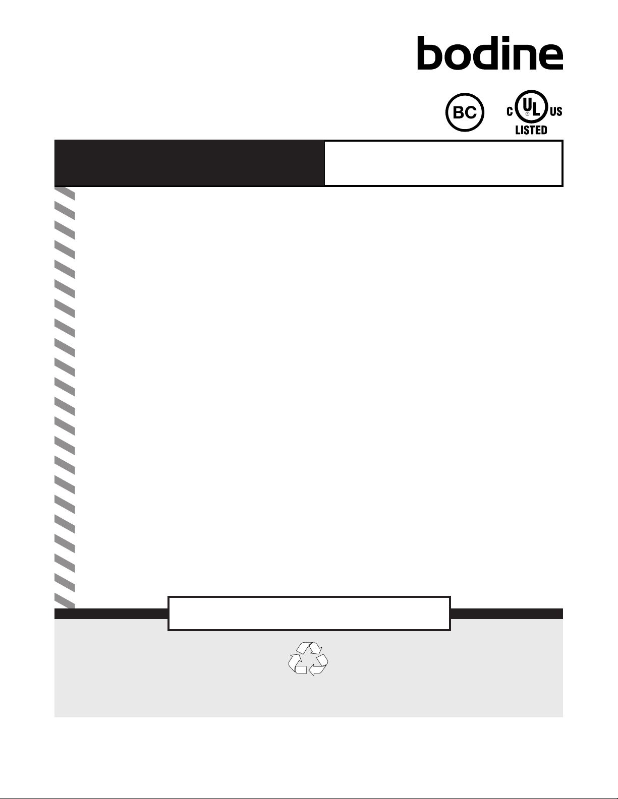
STEP #2a INSTALLING THE 2W-ITS ON FIXTURE SURFACE
> Mount the supplied 2W-ITS (2 wire illuminated test switch) in a location that is
visible and accessible by maintenance personnel. The 2W-ITS mounts through a
½” hole which may need to be made in the luminaire or could come pre-punched
by the luminaire supplier.
> Wire the test switch per wiring diagrams provided on these instructions.
> If wired correctly, the 2W-ITS indicator light should be ON when AC power is
supplied to the fixture, indicating that the emergency inverter battery is
charging. After installing, mark with the "PUSH TO TEST" and "CHARGING
INDICATOR LIGHT" labels.
Hex Nut
2 Wire
Illuminated
Test Switch
Fixture or
Test/Monitor Plate
Drill or Punch
a 1/2” Hole
Violet
Brown
3

During normal operation, AC power is applied and the self-testing emergency driver charges the battery. Connecting the
(red and white) Converter connector wires enables the emergency circuit and supplies power to the control/monitor circuit
and charging indicator light. The self-testing emergency driver continually monitors the unit health. Should the unit detect
an unusual condition, the indicator light will flash.
When AC power fails, the self-testing emergency driver automatically switches to emergency mode, keeping the LED load
illuminated at a reduced lumen output for a minimum of 90 minutes. When AC power is restored, the
self-testing emergency driver returns to charging mode.
OPERATION
SELF-TESTING OPERATION
This unit contains a control/monitor circuit that automatically performs a 30-second discharge test once a month and a
full 90-minute discharge test once a year. During routine testing, the self-testing emergency driver simulates an AC power
failure causing the unit to automatically switch to emergency mode. The unit will monitor the operation of the LED load,
battery voltage, LED load connections and emergency duration. If the emergency system functions properly, then the unit
will return to normal mode. Should the unit detect any problems, the indicator light will flash per failure condition (see
Troubleshooting guide) until the condition has been corrected and the unit passes the next test.
To reset a failure indication, turn off AC power to the emergency driver for a minimum of 10 seconds or briefly push the
2 wire ITS. If the condition has not been corrected by the next scheduled test, the unit will once again detect the failure
and signal the failure indicator.
To perform a manual self-diagnostic test, push and hold 2 wire ITS for minimum of 5 seconds. Once 2 wire ITS is released
the emergency driver will perform a 5 second diagnostic test. During this test, unit will monitor the operation of the LED
load, battery voltage, and LED load connections. If the emergency system functions properly, the unit will return to normal
mode. Should the unit detect any problems, the indicator light will flash per failure condition (see Troubleshooting guide)
until the condition has been corrected and the unit passes the next test.
4
TROUBLESHOOTING GUIDE
STATUS INDICATOR
LIGHT
PROBLEM CORRECTIVE ACTION
Light on not flashing None None, Unit is Operating Correctly.
Flashing 2 times every 5 seconds Battery Error Charge battery. If after an hour failure is still
indicated, see action below.
Flashing 3 times every 5 seconds Charging Error
Ensure input wiring is correct and verify voltage is
correct and stable. (WHITE, BLACK wires)
Flashing 4 times every 5 seconds Output Error
1. Output might be either open or short circuited.
2. Ensure that fixture wiring is in accordance with
proper wiring diagram.
3. Ensure connections of Yellow and Yellow Black
wires.
Continuous Flashing Application out
of range
Ensure
LED load is operational and specified for
self-testing emergency driver
MAINTENANCE
This self testing emergency driver automatically performs required routine testing. Results are reported to
maintenance personnel via the indicator light.
Note: Maintenance personnel should periodically check the indicator light. If the indicator light is flashing, follow steps
in the Troubleshooting Guide.

Failure Status will be reset when the unit passes:
• The next automatic test, or
• Briefly pressing the 2 wire ITS, or
• A power failure exceeding 10 seconds.
NOTE: The converter connector (red and white wires) must be connected for the AC driver to
operate normally.
5
EMERGENCY DRIVER AND AC DRIVER MUST BE FED FROM THE SAME BRANCH CIRCUIT
TYPICAL SCHEMATICS ONLY. MAY BE USED WITH OTHER DRIVERS. CONSULT THE FACTORY FOR OTHER WIRING DIAGRAMS.
WIRING DIAGRAMS
NOTE 1: For short-term testing of the emergency function, the battery must be charged for at least one hour.
The emergency driver must be charged for at least 24 hours before conducting a long-term test.
NOTE 2: The YELLOW, YEL/BLK, VIOLET, BROWN, RED, and WHITE (CONVERTER CONNECTOR) wires are all Class 2.
Tc
222.25 mm
15. mm
TCASE TEST POINT LOCATION
AC LED
DRIVER
WALL
SWITCH
UNSWITCHED HOT
YELLOW
COMMON WHITE
YEL/BLK
OUTPUT (-)
LED LOAD (+)
LED LOAD (-)
WHITE WHT/BLK
WHT/RED
BLUE
OUTPUT (+)
BLACK
BLACK
WHITE
GREEN
GROUND
L
E
D
D
R
I
V
E
R
E
M
E
R
G
E
N
C
Y
VIOLET VIOLET
BROWN BROWN
CONVERTER
CONNECTOR
RED
2W-ITS
AC LED
DRIVER
WALL
SWITCH
UNSWITCHED HOT
YELLOW
COMMON
WHITE
BLUE
WHITE
BLACK
YEL/BLK
OUTPUT (-)
LED LOAD (+)
LED LOAD (-)
WHITE WHT/BLK
THERMAL
PROTECTOR
WHT/RED
BLUE
OUTPUT (+)
BLACK
BLACK
WHITE
OR
RED
GREEN
GROUND
L
E
D
D
R
I
V
E
R
E
M
E
R
G
E
N
C
Y
VIOLET VIOLET
BROWN BROWN
CONVERTER
CONNECTOR
RED
2W-ITS
WITH THERMAL PROTECTOR
Table of contents
Other Bodine Lighting Equipment manuals


