Body flex IT 8020 User manual

OWNER’S MANUAL
* This item is for consumer use only and it is not meant for commercial use.
IT 8020

General Information
IT8020
Page 1
Warranty
Body Flex Sports warrants your product for
a period of 1 year for the frame and 90 days
on all parts if the item is used for the intended
purpose, properly maintained and not used
commercially. Any alterations or incorrect
assembly of the product will void this warranty.
Proof of purchase must be presented for any
warranty validation (no exceptions). This
warranty applies to the original purchaser only
and is not transferable.
This warranty does not cover abuse or defects
caused during use, storage or assembly.
During the warranty period, Body Flex Sports
reserves the right to:
a). provide replacement parts to the
purchaser in an effort to repair the item.
b). repair the product returned to our
warehouse (at the purchaser’s cost).
c). replace the product if neither of the two
previously mentioned actions effect repair.
This warranty does not cover normal wear and
tear on upholstery.
Questions
If you have any questions concerning the
assembly of your item or if any parts are
missing, please DO NOT RETURN THE
ITEM TO THE STORE OR CONTACT THE
RETAILER. Our dedicated customer service
staff can help you with any questions you may
have regarding the assembly of this unit and
can also mail you replacement parts.
Customer Support
Customer Support is open 9:00 a.m. to 5:00
p.m. (Pacific Time) Monday through Friday.
Please contact us by any of the following
means.
Body Flex Sports, Inc.
21717 Ferrero Parkway, Walnut, CA 91789
Telephone: (888) 266 - 6789
Fax: (909) 598 - 6707
Email: info@bodyflexsports.com
Safety
Before you undertake any exercise program,
please be sure to consult with your doctor.
Frequent strenuous exercise should be
approved by your doctor and proper use
of your product is essential. Please read
this manual carefully before commencing
the assembly of your product or starting to
exercise.
• Please keep all children away from this item
when in use. Do not allow children to climb or
play on them when they are not in use.
• Supervise teenagers while they use this unit.
• For your own safety, always ensure that there
is at least 3 feet of free space in all directions
around your product while you are exercising.
• Regularly check to see that all nuts, bolts and
fittings are securely tightened. Periodically
check all moving parts for obvious signs of
wear or damage.
• Clean only with a damp cloth, do not use
solvent cleaners. If you are in any doubt, do
not use your product; contact CUSTOMER
SUPPORT.
• Before use, always ensure that your product
is positioned on a solid, flat surface. If
necessary, use a rubber mat underneath to
reduce the possibility of slipping.
• Always wear appropriate clothing and
footwear such as training shoes when
exercising. Do not wear loose clothing that
could become caught in moving parts during
exercise.
• Do not use this unit if it is not functioning
properly or if it is not fully assembled.
• Do not use this unit for commercial purposes.
Storage and Use
Your product is intended for use in clean
dry conditions. You should avoid storage in
excessively cold or damp places as this may
lead to corrosion and other related problems.
Weight Limit
Your product is suitable for users weighing:
250 pounds or less.
• Before use, you must read and understand all
instructions & warnings stated in this Owner’s
Manual as well as posted on the equipment.
• It is the facility owner’s responsibility to properly
instruct users on the proper operation of the
equipment and to warn them of the potential
hazards.
• If at any time during exercise you feel faint, dizzy
or experience pain, stop and consult your
physician.
Assembling Tools
- Ruler with both metric and English measurements
- 2 x Adjustable Wrenches
- 1 x Philips (”Crosshead”) Screw Driver

Page 2
Hardware List
The following hardware is used to assemble your unit. Please take a moment to familiarize yourself with these items.
PLEASE NOTE: some of these parts may have already been pre-assembled on your unit.
#34 Washer (M10)
[8 pieces]
#33 Washer (M6)
[6 pieces]
#28 Hex Bolt (M6x45 mm) [ 1 piece]
#38 Hex Bolt (M10x35 mm)
[2 pieces]
#25 Hex Bolt (M10x30 mm) [2 pieces]
#29 Lock Nut (M10)
[4 pieces]
#30 Lock Nut (M6)
[3 pieces]
#47 Hex Bolt (M6x15 mm)
[ 2 pieces]
#43 Lock Nut (M8)
[1 piece]
#50 Hex Bolt (M6x10 mm)
[ 3 pieces]
#49 Safety Lock Pin
[2 pieces]
Tool
[1 piece]
Bolts
#56 Hex Bolt (M8x45 mm)
[ 1 piece]
#45 Washer (M8)
[1 piece]
#52. Quick Clip
[1 Piece]
Washer
Nut
Others
IT8020

Page 3
Parts Listing
The following parts list describes all of the parts illustrated on the
exploded diagram on the following page. Please note, most of
these parts are already pre-assembled on your unit.
IT8020
Parts# Description Parts# Description
101 Front Leg Tube 29 Lock Nut (M10)
02A-R Right Cross Support Bracket 30 Lock Nut (M6)
02A-L Left Cross Support Bracket 31 Square Inner Plug (30 mm)
103 Rear Base 32 Curved Washer (M6)
104 Adjustable Ankle Brace 33 Washer (M6)
105 Height Adjustment Tube 34 Washer (M10)
06 Adjustable Pivot Bar 35 Small Pin
07B Backrest Frame 36 Safety Strap with Buckle
108 Adjustable Foot Tube 37 Safety Hook
09 Spring 38 Hex Bolt (M10x35 mm)
10 Square Inner Plug (32 mm) 39 Grip Tape
11 Bumper 40 Pivot Bracket
112 Ankle Brace Tube 41 Plastic Washer (M6)
113R Right Hand Rail 142 Safety Lock
113L Left Hand Rail 43 Lock Nut (M8)
114 Foam Grip 44 Hex Bolt (M8x35 mm)
15R Ri ht C 45 W h (M8)15R Right Cover 45 Washer (M8)
15L Left Cover 47 Hex Bolt (M6x15 mm)
17 Plastic Clip 48 Square Inner Plug (35 mm)
18 Ankle Brace Lock Pin 49 Safety Lock Pin
19 Height Selector Lock Pin 50 Hex Bolt (M6x10 mm)
120 Foam Roller 51 Safety Bar
21 Round Inner Plug (19 mm) 52 Quick Clip
24B Back Rest 53 Spring
25 Hex Bolt (M10x30 mm) 54 Square Inner Plug (20 mm)
26 Hex Bolt (M6x50 mm) 55 Round Inner Plug (22 mm)
27 Hex Bolt (M10x25 mm) 56 Hex Bolt (M8x45 mm)
28 Hex Bolt (M6x45 mm) 57 Rectanguar Inner Plug (20x50 mm)
58 Plastic Clip

The following diagram is provided to help you familiarize yourself with the parts and
hardware that will be used during the assembly process. Please note that not all of the
parts and hardware you see here will be used while you are assembling the machine
because some of these items are already pre-installed. Please continue to the next
page to begin the assembly process and use this page only as a reference guide for
parts and hardware.
Page 4
Exploded Diagram
IT8020

Page 5
A
B
A
#34 Washer (M10) [8 pieces]
#38 Hex Bolt (M10x35 mm)
[2 pieces]
#25 Hex Bolt (M10x30 mm)
[2 pieces]
#29 Lock Nut (M10) [4 pieces]
Bolts
Nuts
Washers
Assembly Instructions
A s s e m b l y S t e p 1
Hardware Required
B.) Hand Rail Assembly
Align the top hole located on the Rear Base (#103)
with the middle hole located on the Pivot Bracket
(#40). Position the Right Hand Rail (#113R)
on the outside of the Rear B ase ( #103) and
position one Safety Hook (#37) on the inside
of the Pivot Bracket (#40)
Insert a Hex Bolt
(#38) through a Washer (#34) followed by the
Safety Hook (#37),Pivot Bracket (#40),Rear
Base (#103), Right Hand Rail (#113R), Washer
(#34) and secure it with a Lock Nut (#29).
Align the lower hole located on the Rear Base
(#103) with the lowest hole located on the Pivot
Bracket (#40) and the lower hole located on
the Right Hand Rail (#113R). Insert a Hex Bolt
(#25) through a Washer (#34) followed by the Pivot
Bracket (#40),Rear Base (#103), Right Hand Rail
(#113-R), Washer (#34) and secure it with one Lock
Nut (#29). Repeat this process on the opposite side.
Please look at the diagrams and make sure
you assembled all of the parts as illustrated.
A.) A-Frame Assembly
Open the pre-assembled A-Frame, which is composed
of Front Leg Tube (#101), Rear Base (#103) and left
and right Cross Support Brackets (#02A-L/R). Make
sure that the two Cross Support Brackets (#02A-L/R)
are fully extended and firmly locked in place by pressing
down on them.
IT8020

Assembly Instructions
C
A
B
A s s e m b l y S t e p 2
Hardware Required
#33 Washer (M6)
[4 pieces]
#30 Lock Nut (M6)
[2 pieces]
#47 Hex Bolt (M6x15 mm)
[2 pieces] #50 Hex Bolt (M6x10 mm)
[2 pieces]
#49 Safety Lock Pin
[2 pieces]
Bolts
Nuts Washers Others
Page 6
IT8020
B.) Adjustable Pivot Bar Installation
A.) Cover Assembly
Slide the Left Cover (#15L) over the Left Hand Rail (#113L)
and
on to the A-Frame ensuring that the notched-out
flap of the Left Cover (#15L) is facing toward the inside
of the A-Frame. Repeat on the opposite side.
C.) Back Cushion Installation
Each Adjustable Pivot Bar (#06) has three holes in it. These three
holes are designed to be a fine-tune adjustment that will allow you to
shift your center of gravity so that you can easily control the rate of
Adjustable Pivot Bars (#06)
the slots located on the Backrest Frame (#07B) ensuring that they both
line up to the top holes. Proceed with these instructions for now and if
you are not satisfied with the amount of control you have during
Adjustable Pivot Bars (#06)
down to the middle hole or to the lowest
NOTE: EACH HANDLE BAR SHOULD BE PROPERLY SEATED INSIDE
EACH BRACKET. A BRACKET PIN SHOULD
EACH HANDLE BAR. BOTH HANDLE BARS SHOULD ALWAYS BE SET
TO THE SAME POSITIONS.
Screw a Hex Bolt (#47) and a Washer (#33) through the bottom of
both Adjustable Pivot Bars (#06) and secure it with a
Washer (#33)
and a Lock Nut (#30). On each side, insert one Safety Lock Pin (#49)
ENGAGE THE HOLE OF
inversion. Insert each of the two
into
hole according to your preference.
Open the Safety Hooks (#37) that you have previously
assembled on the A-Frame. With the help of an assistant,
lift the Backrest Frame (#07B) and align the Adjustable Pivot
Bars (#06) into the two slots. Make sure both sides are properly
seated into each slot. Do not be alarmed if the frame
does not fit perfectly in the slot. Have your assistant gently pry apart
the handle bars to align it for perfect fit. Test the Backrest
Frame (#07B) by rocking it back and forth a few times. After
you have ensured that Backrest Frame (#07B) rotates smoothly, lower the
Safety Hooks (#37) over the Adjustable Pivot Bars (#06)
as far as they will go. Secure the Safety Hooks (#37) in place by
screwing Hex Bolt (#50) through the Pivot Bracket (#40)
and directly in to the Safety Hooks (#37).
the inversion process, please return to this step and move the
through the top hole of both Adjustable Pivot Bars (#06) then through
the bottom hole. These are for an additional safety measure.

Page 7
Note: The holes on these parts must line up in
order for the Bolt (#28) to go through.
C
A
B
#33 Washer (M6)
[2 pieces]
#28 Hex Bolt (M6x45 mm)
[1 piece]
#30 Lock Nut (M6)
[1 piece]
Bolts
Nuts
Washers
#50 Hex Bolt (M6x10 mm)
[1 piece]
Assembly Instructions
A s s e m b l y S t e p 3
Hardware Required
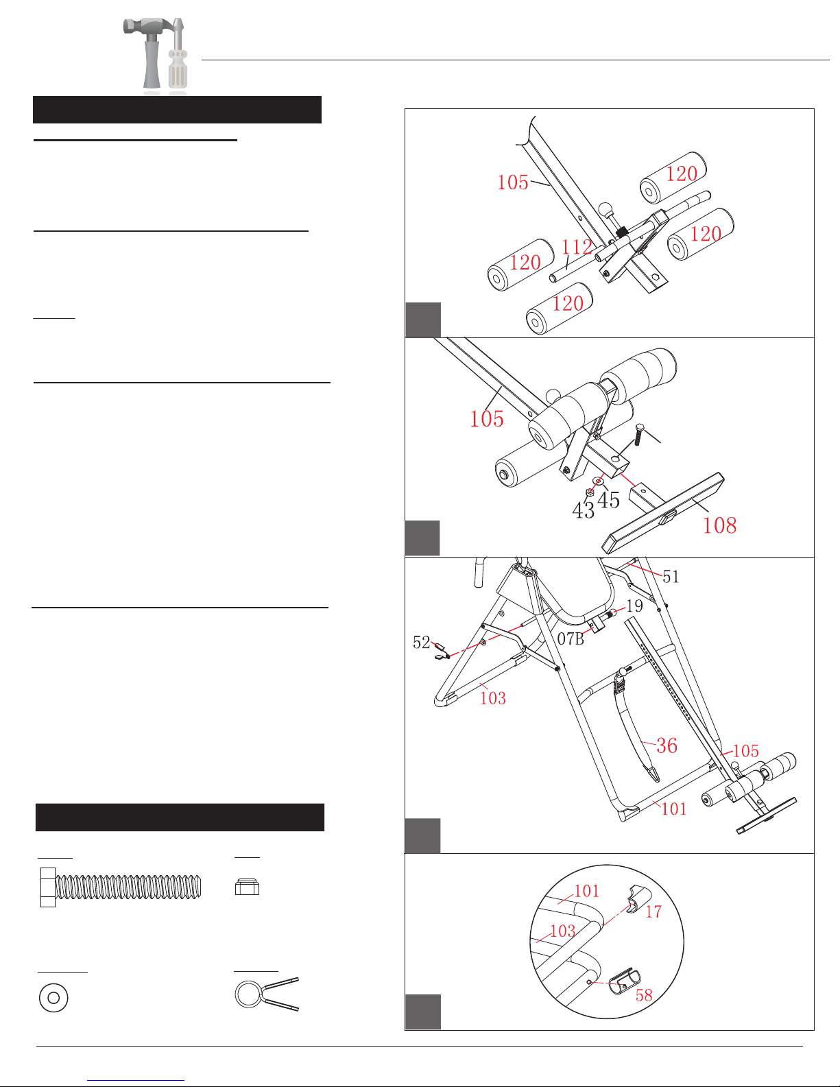
A.) Adjustable Ankle Brace Assembly
C.) Ankle Brace Tube Assembly
Slide the Ankle Brace Tube (#112) through the corresponding
Take the illustrated assembly which is composed of
parts (#105),(#104),(#18),and (#09) out of the box. Pull up the
Ankle Brace Lock Pin (#18) as illustrated and, at the
same time, pull the Adjustable Ankle Brace (#104) out
of the Height Adjustment Tube (#105) SLOWLY. (You will notice
that there is a Spring (#09) that pulls downward as you pull the
Adjustable Ankle Brace (#104) out). After you free the
Adjustable Ankle Brace (#104) out as shown in drawing A,
rotate it 90 degrees counter-clockwise so that the circular round
holes face toward the Ankle Brace Lock Pin (#18), and the long
oval slot faces downward toward the Hex Bolt (#50). Insert the
Adjustable Ankle Brace (#104) back into the Height Adjustment
Tube (#105) and release the Ankle Brace Lock Pin (#18).
NOTE: For your safety, always ensure that the Ankle Brace Lock
Pin (#18) is fully inserted into the circular round hole setting that
holds your feet snugly before inverting.
Next, insert Hex Bolt (#50) through the bottom hole shown in
drawing A and through the long oval slot and tighten.
Please ensure the assembly now looks like drawing B and that
the Ankle Brace Lock Pin (#18) is fully engaged down into a hole.
set of holes on the Height Adjustment Tube (#105). Then,
secure this assembly by using one Hex Bolt (#28), two Washers
(#33) and one Lock Nut (#30) as sequenced in diagram C.
Long oval slot
facing downward
Rotate
90 degrees
B.) Adjustable Ankle Brace Assembly (II)
Hole for
Step B.
IT8020
D
56
C
B
A
Page 8
Hardware Required
D.) Plastic Clip Base Protectors
The 4 Plastic Clips (#17/#58) add stability and safety to the unit.
The assembly process is now complete, HOWEVER , please do not
use the inversion table until you have completed reading the manual
to learn about the safety features and operation procedures.
the
Slide the Safety Bar (#51) into either the top set of holes or
the bottom set on the Rear Base (#103) and secure it with a
Quick Clip (#52).
Height Adjustment Tube (#105) up or down.
Ensure that four Plastic Clips (#17/#58) are installed on the
Front Leg Tube (#101) and Rear Base (#103) before using
the unit. If for any reason they are not installed on the unit,
follow these simple steps to install them.
First, lift the front end up and you will notice that there is a hole
on the bottom. Insert the clip pin on the Plastic Clip (#17) into
the hole on the Front Leg Tube (#101) and snap it into place.
Repeat this process to snap the Plastic Clip (#58) into the
Rear Base (#103) if neccessary.
#43 Lock Nut (M8) [1 piece]
Bolts
#56 Hex Bolt (M8x45 mm) [ 1 piece]
#45 Washer (M8) [1 piece] #52. Quick Clip
[1 Piece]
Washer
Nut
Others
A s s e m b l y S t e p 4
A.) Foam Roller Assembly
Slide the two Foam Rollers (#120) onto the Height
Adjustment Tube (#105) and another two on the Ankle
Brace Tube (#112). Apply soapy water to the tubes if the
foam rollers do not slide on easily.
B.) Adjustable Foot Tube Assembly
Slide the Adjustable Foot Tube (#108) with the “UP” sticker
facing up in the Height Adjustment Tube (#105) and secure
it with one Hex Bolt (#56), one Washer (#45) and one Lock
Nut (#43).
NOTE: Any settings should always hold your feet snugly
during inversion for your safety.
(ALWAYS WEAR ATHLETIC SHOES BEFORE INVERTING!)
C.) Height Adjustment Tube Assembly
With the help of an assistant, attach the Height Adjustment
Tube (#105) to the Backrest Frame (#07B)
by pulling the
Height Selector Lock Pin (#19) out and simultaneously
sliding the Height Adjustment Tube (#105) in. Release the
Height Selector Lock Pin (#19) to any setting for now.
The Height Adjustment Tube (#105) is designed to
accommodate the height of various users; set it accordingly
by pulling the Height Selector Lock Pin (#19) as you slide
Assembly Instructions
IT8020

Safety Instructions
A
Page 9
The Safety Lock is pre-installed on your inversion unit. It consists of the Safety Lock (#142), Spring (#53), Washer
(#33), and Lock Nut (#30).
To UN-LOCK Your Unit:
1. PUSH the Lock Nut (#30) end inward as shown in drawing B.
2. PULL the Safety Lock (#142) outward at the same time.
3. TWIST the Safety Lock (#142) off of the Height Adjustment
Tube (#105). There is no need to remove the Safety Lock (#142)
4. Your unit is now unlocked. PLEASE REMEMBER TO
LOCK THE UNIT WHEN NOT INVERTING AND/OR WHEN
THE UNIT IS NOT IN USE FOR THE SAFETY OF YOU
AND THOSE AROUND YOU.
To LOCK Your Unit:
1. PUSH the Lock Nut (#30) end inward as shown in drawing B.
2. PULL the Safety Lock (#142) outward at the same time.
3. TWIST the Safety Lock (#142) and place it over and on the
Height Adjustment Tube (#105) as show in drawing A.
4. Your unit is now ‘locked’. ALWAYS KEEP THE SAFETY LOCK
IN THE LOCKED POSITION WHEN NOT INVERTING AND/OR
WHEN THE UNIT IS NOT IN USE FOR THE SAFETY OF YOU
AND THOSE AROUND YOU.
B
‘Locked’ Position
Safety Lock
WARNING: 250 lb. WEIGHT CAPACITY
DO NOT USE THIS INVERSION TABLE WITHOUT A PHYSICIAN’S APPROVAL IF YOU
HAVE ANY OF THE FOLLOWING CONDITIONS (This list is for reference only and is
not an exhaustive listing): Pregnancy, Hiatal Hernia, Ventral Hernia, Glaucoma, Retinal
Detachment or Conjunctivitis; High Blood Pressure, Hypertension, recent Stroke or Transient
Ischemic Attack; Heart or Circulatory Disorders for which you are being treated; Spinal Injury;
Cerebral Sclerosis; Acutely Swollen Joints; Bone Weakness (Osteoporosis), recent unhealed
fractures, medulary pins and/or surgically implanted orthopedic supports; the use of anticoagulants,
including high doses of aspirin; Middle Ear Infections; Extreme Obesity.
IF YOUR PHYSICIAN PERMITS YOU TO USE INVERSION THERAPY, DO SO UNDER
THEIR DIRECTION AND HAVE OUR GUIDELINES APPROVED BY YOUR PHYSICIAN.
DO NOT LET CHILDREN USE THE INVERSION TABLE UNSUPERVISED.
THERE ARE CERTAIN PEOPLE WHO SHOULD NEVER INVERT. IF YOU THINK YOU
BELONG TO THIS MINORITY, PLEASE CHECK WITH YOUR PHYSICIAN BEFORE USING
THIS INVERSION TABLE.
IMPORTANT:
ALWAYS ENSURE SAFETY HOOKS
ARE LOCKED IN PLACE BEFORE USE.
Always secure your ankles by Adjusting top rollers (using pull pin) as close to bottom rollers
as possible at a comfortable but snug position.
**BE SURE PULL PIN LOCKS INTO PLACE IN ORDER TO SECURE ANKLES!**
142 105
30
30
105
142
General Safety
IT8020

Safety Instructions
Page 10
IT8020
Strap Adjustment
ALWAYS ENSURE BOTH ENDS OF THE SAFETY STRAP ARE SECURELY CLIPPED TO THE UNIT PRIOR TO USE.
The buckle of the Safety Strap should be positioned about halfway down the Safety Strap with the concave side facing up.
The two ends of the buckle should show; the middle slot should be covered up by the Safety Strap.
Feed the free end of the Safety Strap through the buckle under one end, over the middle and under the other end.
The buckle should be fastened to allow length adjustment on the Safety Strap loop.
The shorter the strap, the less the angle of inversion; The longer the strap, the greater the inversion angle.
To Shorten the Strap: Feed the upper strap through the buckle and pull the loose lower strap.
To Lengthen the Strap: Feed and pull the upper strap through the buckle.
To prevent serious injury, death, and/or unexpected inversion incline, always rock the backpad back to gauge the maximum inversion
permitted by the strap before using the unit,
First time users should adjust the tether strap by shortening it for minimal inversion.
THE FIRST TIME THAT YOU USE THIS INVERSION TABLE, HAVE SOMEONE WITH YOU TO WATCH YOU. ALTHOUGH
THE INVERSION TABLE IS EASY TO USE, HAVING SOMEONE NEARBY TO “SPOT” YOU WILL PROVIDE YOU WITH
COMFORT AND ENSURE YOU HAVE THE CORRECT INITIAL SETTINGS.
Before starting, ensure that the Inversion Table is at the correct settings to match your height and weight. As each individuals’
body type is different, you will need to find the correct settings for you personally.
ENSURE THAT ALL PULL PINS ARE TIGHT AND ENTIRELY IN THE HOLES.
ALWAYS MAKE SURE THAT THE SAFETY STRAP IS ATTACHED.
AVOID INVERTING AFTER MEALS.
This end attached here
This end attached here
Feed strap
then pull
Feed strap
and pull
SHORTEN
STRAP
LENGTHEN
STRAP

Usage Guidelines
Page 11
IT8020
1. Before You Begin
• Always ensure the two Cross Support Brackets of the A-frame are pushed
down and locked horizontally in place.
• Always ensure that the Safety Hooks on both sides are latched over and
securely holding the Adjustable Pivot Bars.
• Always check that all nuts and bolts are tightened and have not come loose and are in good condition (i.e. not cracked,
not rusty, etc.)
2. Select An Inversion Mode with Safety Bar
a. Decide what mode of inversion you would like:
• Easy (less than 22°)
• Medium (22-55°)
• Expert (over 55°)
b. Once you decide, pull out the Safety Bar from the front locked position.
Then, place the Safety Bar in 1 of the 3 places below:
• Easy (less than 22°): upper set of holes on Rear Frame
• Medium (22-55°): lower set of holes on Rear Frame
• Expert (over 55°): set it aside where it will not interfere or become a
safety hazard throughout the mounting, inversion, and dismounting
process, but, where you can easily retrieve it directly after you complete
your inversion workout. We suggest placing it up against the inner side
of the Rear Frame and the ground.
3. Setting Up with the Safety Strap
a. Unlock the Safety Lock from the Adjustable Height Bar.
Without mounting, first test the Back Rest inversion angle by tilting
it back to check where it will stop and make any necessary length adjustments to the Safety Strap.
If you are using the Safety Bar for Easy or Medium inversion, please leave at least a
1” distance between the Safety Bar and the backpad for your safety
(i.e. when fully inverted, the Back Rest should not touch the Safety Bar).
Please refer to the “Strap Adjustment” section
of the Safety Instructions for instructions and more details on how to
adjust the Safety Strap.
NOTE: The Safety Strap gives you the most control over your inversion
safety and angling. The Safety Bar feature is designed as a secondary
security measure to prevent over-inversion. We do not suggest the
Back Rest reach the Safety Bar during inversion.
Cross support brackets
pushed down fully
to locked position
Safety hooks on
both sides securely
latched over
Back Rest DOES NOT
touch the Safety Bar;
ensure there is at least a 1”
gap when at maximum
inversion permitted by
Safety Strap
Before use,
unlock the Safety Lock
to test for Back Rest
inversion
Place Safety Bar
in 1 of the 3 positions
shown

Usage Guidelines
Page 12
5. Mounting Safely
a. With one foot firmly planted on the ground, step or slide your other foot onto the Adjustable Foot Tube.
When you have enough stability, then proceed to mount your grounded foot. Pull up the Ankle Brace Lock Pin
again, this time adjusting it so that the foam rollers are snug and secure around your ankles. Please ensure
the Ankle Brace Lock Pin is fully inserted and securely in place.
Now, remove the Safety Lock to the unlocked position. You may find that you need to bend forward slightly to do so.
If you have any back problems or do not feel comfortable doing this, have an assistant unlock the Safety Lock for you.
We advise having an assistant to “spot” you during your first few inversion sessions so you can familiarize
yourself with the exercise and machine.
4. Make Adjustments & Prepare to Mount
b. Now, place the Safety Lock back into the locked position across the Height Adjustment Tube. To prevent serious
injury or even death, please do not skip this step. The Safety Lock is a key safety feature and should be placed in
the locked position any time the user is not in the inverting condition, even if just resting in the upright position.
c. Adjust the Height Adjustment Tube to the most suitable setting for you. Because of different body sizes, you
may find that the most suitable setting may not match your actual height.
d. Pull up the Ankle Brace Lock Pin to release the Adjustable Ankle Brace and pull the Adjustable Ankle Brace
to a wider setting so that you have enough space to mount your feet.
Please remember to read all Safety Instructions and information in this manual prior to inversion.
Before mounting, lock the Safety Lock. Adjust the Height Adjustment Tube
to best accommodate your body.
Pull up the Ankle Brace Lock Pin
and pull the Adjustable Ankle Brace
to a wider setting.
Mount one foot onto the
Adjustable Foot Tube.
When you are stable and balanced,
mount the second foot.
Then, secure the Adjustable Ankle Brace
snug and secure over your ankles
(by pulling up on the Ankle Brace Lock Pin again).
Now, remove the Safety Lock to the unlocked
position.
IT8020

Usage Guidelines
Page 13
6. Workout
a. After you have set up and mounted the inversion table as described in steps 3. and 4. above:
i.Slowly lift one arm. You will feel gravity work as it starts
to tilt you back.
iii.Relax and enjoy the inversion. iv.Reverse out of inversion and return to an upright
position by slowly lifting one arm back to your side.
v.Then slowly lift the other arm back.
* Please use the Safety Rail handlebars if you need to at any time to assist you when you go to invert
or return from inversion.
IT8020
ii.Continue inverting by slowly raising the other arm.

Usage Guidelines
Page 14
7. Dismounting
a. Before stepping off the unit, lock the Safety Lock back to locked position over the Height Adjustment Tube.
Again, please have an assistant help you, if necessary.
b. Pull the Ankle Brace Lock Pin up to release the foam rollers from around your ankles. Using the Safety Rail handlebars
or the frame to ensure your balance and stability, place one foot onto the ground. Then, once you have balance on
your first foot, step your second foot down onto the ground. Retrieve the Safety Bar (which was removed from Step 2.)
and insert it through the set of holes at the front of the unit, returning it into the locked position.
After your workout and before you dismount the unit,
lock the Safety Lock.
Release your ankles from the Adjustable
Ankle Brace (foam rollers) by pulling
on the Ankle Brace Lock Pin.
With stability and control, lower one
foot onto the ground. When you
are balanced on the first foot, then
you may proceed to lower your
second foot.
Lastly, retrieve the Safety Bar (removed during Step 2) and insert it through the front set of holes to the “locked” position.
FOR THE SAFETY OF YOU AND THOSE
AROUND YOU:
Always lock the
Safety Bar here through front set
of holes (over the Height Adjustment Tube)
to prevent serious injury & unsupervised usage
of the unit.
IT8020

Model Number IT8020
version:5-18-2011
Table of contents
Popular Fitness Equipment manuals by other brands

SA Sport
SA Sport 135 quick start guide

Hoist Fitness
Hoist Fitness MC-7020 owner's manual

Waterflex
Waterflex AquaJogg user manual

Enovative Technologies
Enovative Technologies e-Pulse Ultra quick start guide

Dynatronics
Dynatronics Bird & Cronin Ranier Romer quick guide

ParaBody
ParaBody 914101 Assembly instructions


