Bodyfit BDEX2496.0 User manual

RECUMBENT BIKE
Owner’s Manual
Model No. BDEX2496.0
SKU No. 20181611
BEFORE YOU BEGIN
BDEX2496.0
PLEASE DO NOT RETURN TO STORE; CALL OUR CUSTOMER SERVICE DEPARTMENT FIRST AT 1-877-872-6970
2
•A flat area of 5’ x 4’ will be required to assemble and properly use the BF Recumbent Bike.
• For your benefit, read this manual carefully before using the BF Recumbent Bike. Please review the explod-
ed diagram and familiarize yourself with the parts that are labeled.
• Before beginning assembly, make sure to read the information on this page. This brief introduction will help
you with assembly and save you time.
•Assembly Requires Two Persons. For your convenience and safety, assemble the BF Recumbent Bike
with the help of another person.
•Set Aside Enough Time. The BF Recumbent Bike has many features, so the assembly process will take
approximately 30 to 60 minutes. Assembly will go smoothly if you set aside plenty of time and decide to
make the task enjoyable.
•Select A Location. Because of its weight and size, the BF Recumbent Bike should be assembled in the
location where it will be used. Make sure that there is enough room to walk around the BF Recumbent Bike
as you assemble it.
•How to Unpack the Box. Place all parts of the BF Recumbent Bike in a cleared area and remove the pack-
ing materials. Do not dispose of the packing materials until assembly is completed.
Note: The assembly
hardware for the BF Recumbent Bike can be found in the carton.
•Tools Required For Assembly. Assembly will require a hex key, a Phillips screwdriver, and an adjustable
wrench.
•How to Identify Parts. Remove all the parts from the carton and carefully place them on the floor. To help
you identify the small parts used in assembly, we have included a PARTS LIST in this manual. Place the list
on the floor and use it to easily identify parts during each assembly step.
Note: Some small parts may have
been preattached. If a part is not in the parts bag, check to see if it has been preattached.
•Tightening Parts. Tighten all parts as you assemble them, unless instructed to do otherwise.
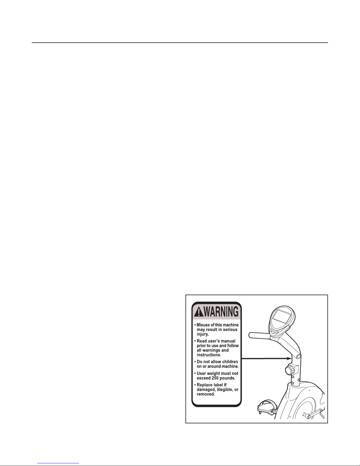
• The decal shown to the right has been placed
on the recumbent bike. If the decal is missing
or illegible, call the toll-free telephone number
on the back cover of this manual and order a
free replacement decal. Apply the decal in the
location shown.

IMPORTANT: Read all instructions carefully before using this product. Retain this
owner’s manual for future reference.
• Thank you for purchasing our product. Even though we make great efforts to ensure the quality of each prod-
uct we produce, occasional errors and/or omissions do occur. If you should find this product to have either a
defective part or a missing part, please contact us for a replacement.
• This product has been designed for home use only. Product liability and guarantee conditions will not apply to
products being subjected to professional use or to products being used in a gym center.
• This exercise equipment was designed and built for optimum safety. However, certain precautions apply
whenever you operate exercise equipment. Make sure to read the entire manual before assembling and oper-
ating this machine. Also, please note the following safety precautions:
1. Keep children and pets away from this equipment at all times.
2. Only one person at a time should use this equipment.
3. If you experience dizziness, nausea, chest pains, or any other abnormal symptoms while using this equip-
ment, STOP the workout at once. CONSULT A PHYSICIAN IMMEDIATELY.
4. Always use this equipment on a clear and level surface. Do not use it outdoors or near water.
5. Keep hands and feet away from any moving parts.
6. Do not insert any object into any openings.
7. Read all instructions before assembly and operation.
8. Before using this equipment to exercise, always perform stretching exercises to properly warm up.
9. Use this equipment only for its intended use as described in this manual.
10. Always wear appropriate workout clothing and shoes when exercising; do not wear robes or other cloth-
ing that could become caught in the equipment.
• Weight on this product should not exceed 250 pounds.
• Exercise of a strenuous nature, as is customarily done on this equipment, should not be undertaken without
first consulting a physician. No specific health claims are made or implied as they relate to the equipment.
Measurements made by the equipment are believed to be accurate, but only the measurements of your
physician should be relied upon.
WARNING: BEFORE BEGINNING ANY EXERCISE PROGRAM, CONSULT YOUR PHYSICIAN.
THIS IS ESPECIALLYIMPORTANT FOR INDIVIDUALS OVER THE AGE OF 35 OR PERSONS
WITH PRE-EXISTING HEALTH PROBLEMS. READ ALL INSTRUCTIONS BEFORE USING ANY
FITNESS EQUIPMENT. WE ASSUME NO RESPONSIBILITY FOR PERSONAL INJURY OR
PROPERTY DAMAGE SUSTAINED BY OR THROUGH THE USE OF THIS PRODUCT.
SAFETY & PRECAUTIONS
BDEX2496.0
PLEASE DO NOT RETURN TO STORE; CALL OUR CUSTOMER SERVICE DEPARTMENT FIRST AT 1-877-872-6970
3

Before You Begin ..........................................................................2
Safety & Precautions ....................................................................3
Exploded Diagram ........................................................................5
Parts List ........................................................................................6–7
Assembly Instructions .................................................................8–11
Console Instructions .................................................................12–13
Training Instructions ....................................................................14
Limited Warranty ..........................................................................15
TABLE OF CONTENTS
BDEX2496.0
PLEASE DO NOT RETURN TO STORE; CALL OUR CUSTOMER SERVICE DEPARTMENT FIRST AT 1-877-872-6970
4
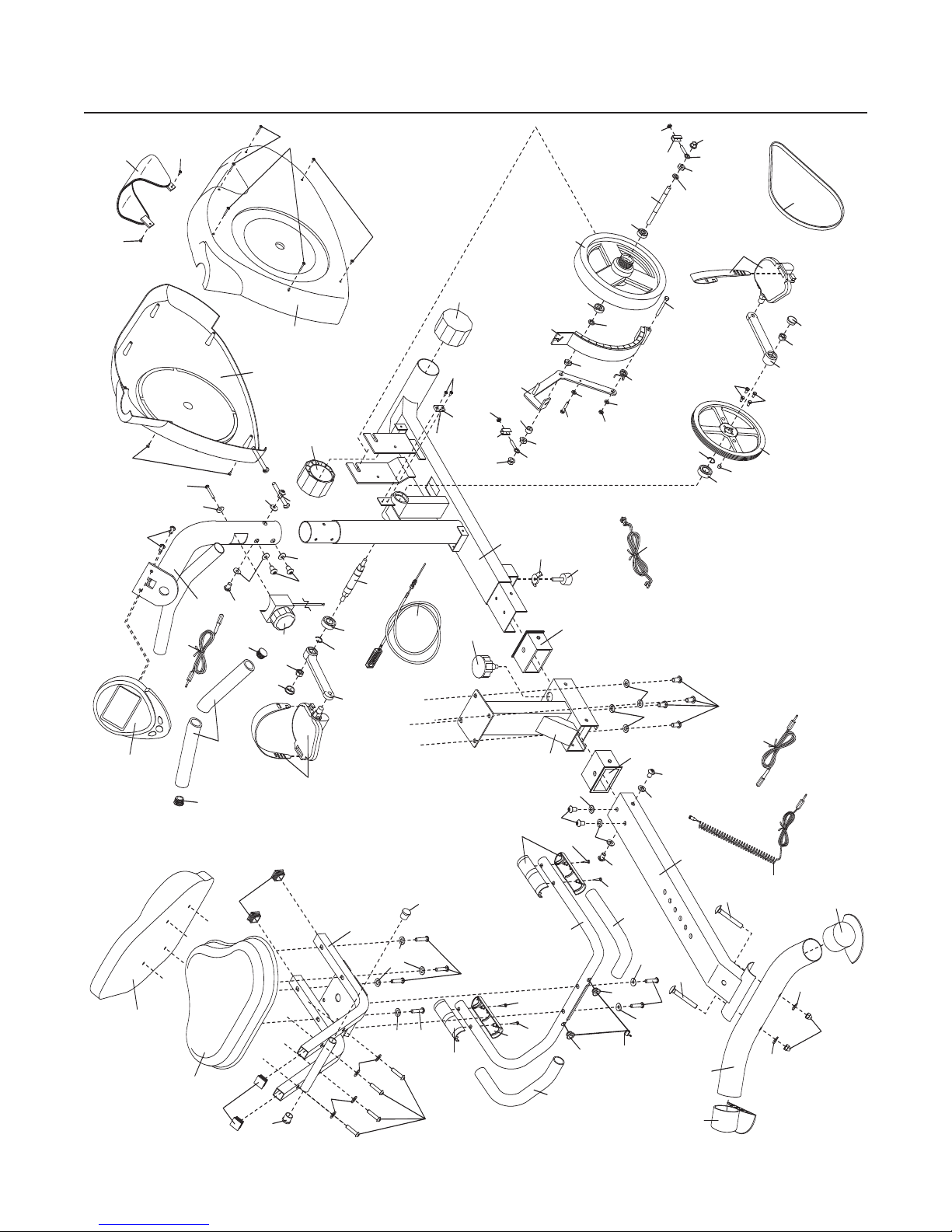
EXPLODED DIAGRAM
BDEX2496.0
PLEASE DO NOT RETURN TO STORE; CALL OUR CUSTOMER SERVICE DEPARTMENT FIRST AT 1-877-872-6970
1
2
2
2
3
4
5
6
67
8
8
9
10
11
12
13
14
15
16
16
17
17
18
19
20
21
22
23
24
25
26
26
27
28
29
30
31
32
33
34
34
35
37
37
36
36
39
40
41
42
43
44
44
45
45
46
47 47
48
49
53
51
51 51
51
51
51
52
52
52
52 52
52
52
50
50
54
54
54
54
54 54
54 54 54
55
55
56
38
57
57
59
59
58
60
60
60 60
51
62
62
62
63
64 65
66
67
67
68
68
69
69
70
71
73
74
76
77
77
78
79
79
75
71
68
72
66
66 61
80
5

PARTS LIST
PLEASE DO NOT RETURN TO STORE; CALL OUR CUSTOMER SERVICE DEPARTMENT FIRST AT 1-877-872-6970
BDEX2496.0
1. Console 1
2. Handgrip pulse sensors 2
3. Handlebar 1
4. Handlebar upright 1
5. Pulse wire 1
6. Handlebar endcaps 2
7. Short foam grips 2
8. “U” brackets 2
9. Resistance control and cable 1
10. Lower Resistance cable 1
11. Seat 1
12. Seat post 1
13. Frame 1
14. Rear frame 1
15. Rear stabilizer 1
16. Front endcaps 2
17. Rear stabilizer endcaps 2
18. Seat adjustment knob 1
19. Drive belt 1
20. Left side shield 1
21. Right side shield 1
22. Left pedal with strap 1
23. Right pedal with strap 1
24. Handlebar upright wire 1
25. Reed switch and wire 1
26. 6003ZZ bearings 2
27. Crank 1
28. Crank pulley 1
29. Flywheel bracket 1
30. “C” magnet 1
31. Flywheel 1
32. Magnet 1
33. Flywheel axle 1
34. 6000Z bearings 2
35. Seat carriage 1
36. Long foam grips 2
37. Seat post sleeves 2
38. M10 left hand flange nut 1
39. Foot 1
40. Seat back 1
41. Left crank arm 1
42. Right crank arm 1
43. “C” magnet spring 1
44. Crank endcaps 2
45. Seat support endcaps 2
46. Rear extension wire 1
47. Seat carriage endcaps 4
48. Wing nut 1
49. Front extension wire 1
50. Handlebar grommets 2
# Description Qty # Description Qty
6

PARTS LIST
PLEASE DO NOT RETURN TO STORE; CALL OUR CUSTOMER SERVICE DEPARTMENT FIRST AT 1-877-872-6970
BDEX2496.0
51. M8 x 12mm screws 12
52. M8 x 20mm curved washers 8
53. M4 x 10mm screws 2
54. M8 x 20mm washers 16
55. 3/8" flange nuts 2
56. M10 x 1.25mm locknut 1
57. #17 snap ring 2
58. M8 nylon nuts 2
59. M8 x 70mm carriage bolts 2
60. #4 x 20 screws 4
61. Side shield cover 1
62. M8 x 40mm screws 8
63. M8 x 38mm screws 2
64. M5 x 15mm curved washer 1
65. M5 x 50mm screw 1
66. #3 x 10 screws 4
67. M6 eyebolts 2
68. 3/8" nylon nuts 3
69. M6 nylon nuts 2
70. M10 x 16 x 10mm spacer 1
71. M10 x 14mm washers 2
72. M5 x 35mm screw 1
73. M6 x 43mm bolt 1
74. M6 washer 1
75. M5 x 15mm washer 1
76. M6 nylon nut 1
77. M5 x 3mm hex screws 4
78. #4 x 40 screws 2
79. M5 x 10mm screws 4
80. Upper Wire 1
# Description Qty # Description Qty
7

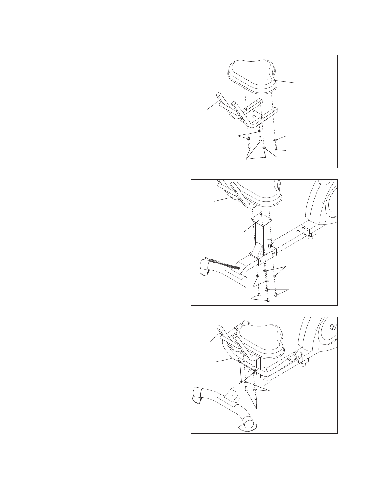
STEP 1
Attach the Rear Stabilizer (15) to the Rear Frame (14)
with two M8 X 70mm Carriage Bolts (59), two
M8 x 20mm Curved Washers (52), and two M8 Nylon
Nuts (58).
If necessary, place a piece of tape over each
M8 X 70mm Carriage Bolt (59) to hold it in place as
you perform this step.
STEP 2
Orient the Seat Post (12) as shown. Loosen the Seat
Adjustment Knob (18) and slide the Seat Post onto
the Rear Frame (14). Align the the Seat Post with one
of the holes in the Rear Frame and tighten the Seat
Adjustment Knob into the hole.
ASSEMBLY INSTRUCTIONS
PLEASE DO NOT RETURN TO STORE; CALL OUR CUSTOMER SERVICE DEPARTMENT FIRST AT 1-877-872-6970
BDEX2496.0
8
14
15
59
59
52
52
58
18
12
14
STEP 3
Pull the Rear Extension Wire (46) from the inside of
the Rear Frame (14). Pull the Front Extension Wire
(49) from the inside of the Frame (13). Connect the
Rear Extension Wire to the Front Extension Wire.
Slide the Rear Frame (14) onto the Frame (13). Attach
the Rear Frame to the Frame with four M8 x 12mm
Screws (51) and four M8 x 20mm Washers (54).
13
54 51
46
49
54 54
51
51
14
ASSEMBLY INSTRUCTIONS
BDEX2496.0
STEP 4
Orient the Seat Carriage (35) as shown and attach the
Seat (11) to the Seat Carriage with four M8 x 40mm
Screws (62) and four M8 x 20mm Washers (54).
STEP 5
Attach the Seat Carriage (35) to the Seat Post (12) as
shown with four M8 x 12mm Screws (51) and four
M8 x20mm Washers (54).
PLEASE DO NOT RETURN TO STORE; CALL OUR CUSTOMER SERVICE DEPARTMENT FIRST AT 1-877-872-6970
9
STEP 6
Have a second person hold the Handlebar (3) orient-
ed as shown. Attach the Handlebar to the Seat
Carriage (35) with two M8 x 38mm Screws (63) and
two M8 x 20mm Curved Washers (52).
35
62
62
54 54
11
54
54
12
35
54
51
3
35
52
63
51
STEP 7
Attach the Seat Back (40) to the Seat Carriage (35)
with four M8 x 40mm Screws (62) and four
M8 x 20mm Washers (54).
Connect the Rear Extension Wire (46) to the Pulse
Wire (5).
ASSEMBLY INSTRUCTIONS
BDEX2496.0
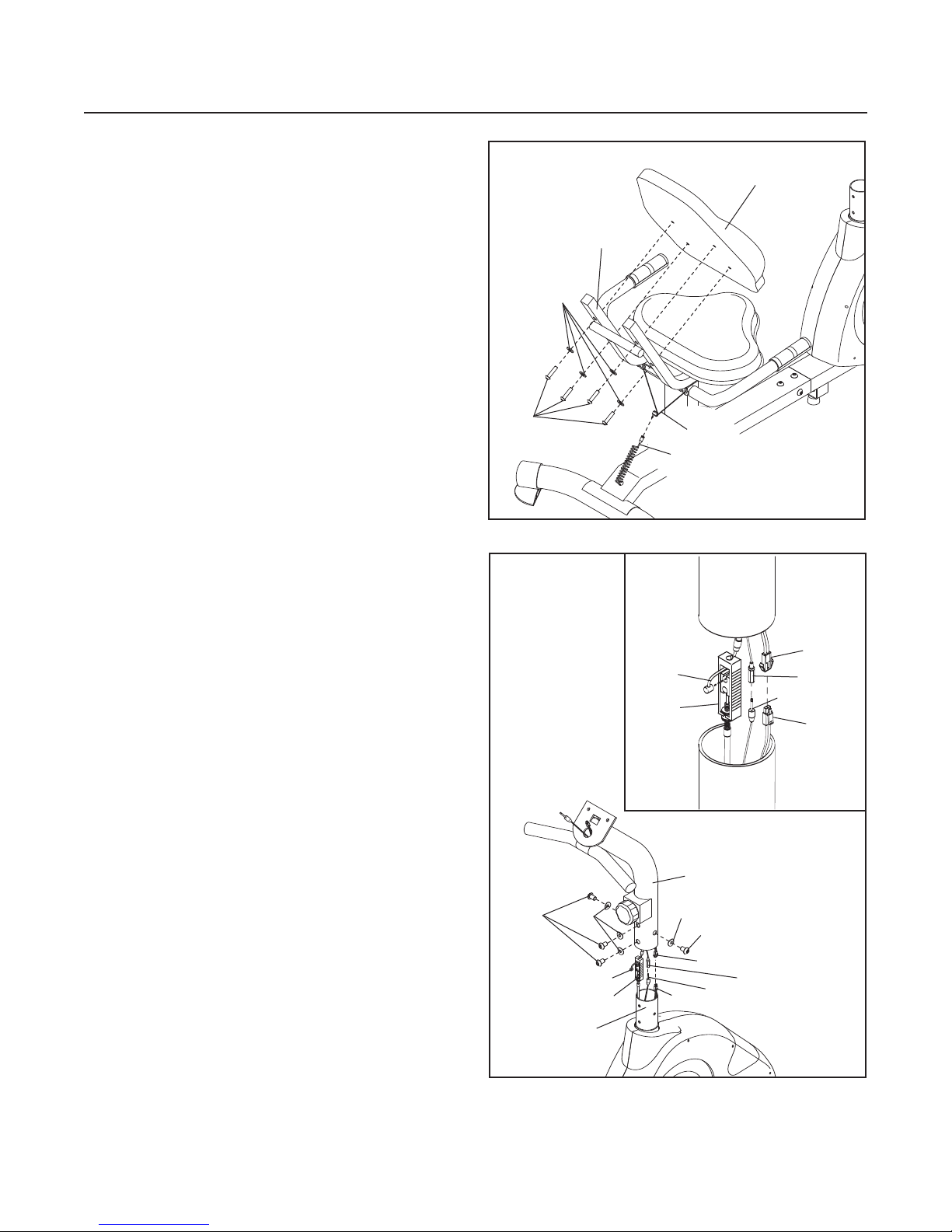
STEP 8
Have a second person hold the Handlebar Upright (4)
in the position shown. See the inset drawing. Connect
the Upper Wire (80) to the Reed Switch Wire (25).
Connect the Handlebar Upright Wire (24) to the Front
Extension Wire (49).
See the inset drawing. Connect the Resistance
Control Cable (9) to the plastic connector on the
Lower Resistance Control Cable (10) in the following
way:
• Insert the end of the Resistance Control Cable (9)
through the connector as shown. Next, press the
small cylinder on the end of the Resistance Control
Cable into the hole in the connector.
• Pull the Resistance Control Cable (9) upward and
insert it into the hole in the top of the connector.
• Remove the metal clip (not shown) from the bottom
of the connector.
Slide the Handlebar Upright (4) onto the Frame (13).
Be careful to avoid pinching the wires and the
cables. Attach the Handlebar Upright (4) with four
M8 x12mm Screws (51) and four M8 x 20mm Curved
Washers (52).
PLEASE DO NOT RETURN TO STORE; CALL OUR CUSTOMER SERVICE DEPARTMENT FIRST AT 1-877-872-6970
10
62
46
40
35
54
5
51 51
80 24
49
25
10
13
9
52 52
4
49 24
80
9
10 25
ASSEMBLY INSTRUCTIONS
BDEX2496.0
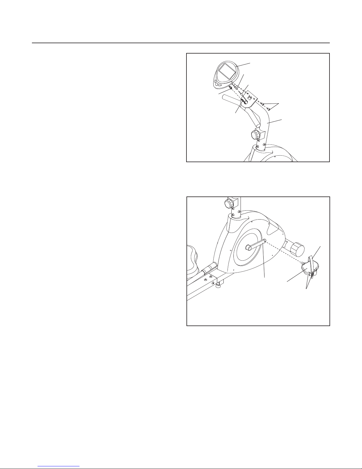
STEP 9
The Console (1) requires two 1,5 V “AA” batteries.
Remove the battery cover from the back of the
Console, and insert two batteries into the battery com-
partment. Make sure that the batteries are oriented
as shown by the diagram inside the battery com-
partment. Then, reattach the battery cover.
Have a second person hold the Console (1) near the
Handlebar Upright (4). Connect the console wire to
the Upper Wire (80). Connect the pulse wire on the
console to the Handlebar Upright Wire (24). Insert the
excess wire into the Handlebar Upright.
Slide the Console (1) onto the Handlebar Upright (4)
and attach it with two M4 x 10mm Screws (53). Be
careful to avoid pinching the wires.
STEP 10
Identify the Right Pedal (23), which is marked with a
sticker. Using the included wrench, firmly tighten the
Right Pedal
clockwise
into the right arm of the Crank
(27). Tighten the Left Pedal (not shown)
counterclock-
wise
into the left arm of the Crank. Important:
Tighten both Pedals as firmly as possible. After
using the exercise cycle for one week, retighten
the Pedals. For best performance, the Pedals must
be kept tightened.
Adjust the strap on the Right Pedal (23) to the desired
position. Then, press the end of the strap onto the
tabs on the Right Pedal. Adjust the Left Pedal strap
(not shown) in the same way.
PLEASE DO NOT RETURN TO STORE; CALL OUR CUSTOMER SERVICE DEPARTMENT FIRST AT 1-877-872-6970
11
Strap
Tabs
23
27
53
Console Wire
80
24
Pulse Wire
1
4

CONSOLE INSTRUCTIONS
BDEX2496.0
PLEASE DO NOT RETURN TO STORE; CALL OUR CUSTOMER SERVICE DEPARTMENT FIRST AT 1-877-872-6970
12
FEATURES OF THE CONSOLE
The easy-to-use console features five displays that
provide instant exercise feedback during your work-
outs. The displays are described below.
Speed—This display shows your pedaling speed, in
miles or kilometers per hour.
Time —This display shows the elapsed time. Note: If
you set a time goal (see step 2), this mode will display
the time remaining in your workout.
Distance—This display shows the distance you have
pedaled during your workout, in miles or kilometers.
Note: If you set a distance goal (see step 2), this dis-
play will show the distance remaining in your workout.
Calories—This display shows the approximate num-
ber of calories you have burned during your workout.
Note: If you set a calorie-burning goal (see step 2),
this display will show the number of calories still to be
burned in your workout.
Pulse—This display shows your heart rate in beats
per minute when the console detects your pulse.
When no pulse is detected, a “P” will be shown in the
display.
HOW TO USE THE CONSOLE
Make sure that there are batteries in the console (see
assembly step 9 on page 11). If there is a sheet of
clear plastic on the face of the console, remove it.
Note: When batteries
are inserted into the
console, a “1” will
begin to flash in the
Speed display. At this
point, you can set the
console to display
speed and distance in either miles or kilometers.
Select a unit of measurement by pressing the MODE
button once or twice; select “1” for kilometers or “2” for
miles. A few seconds after you have selected “1” or
“2,” the unit of measurement will be set.
Follow the steps below to operate the console.
1. Turn on the console.
To turn on the console, press any button on the
console or simply begin pedaling.
2. Set a workout goal if desired.
To set a time, dis-
tance, or calorie-burn-
ing goal for your work-
out, press the MODE
button repeatedly until
the word SET begins
to flash in the Time,
Distance, or Calories display.
Next, press the SET button repeatedly to set a
goal. To set a goal quickly, hold down the SET but-
ton. To reset the goal, press the RESET button
while the word SET is flashing in the display.

13
CONSOLE INSTRUCTIONS
BDEX2496.0
PLEASE DO NOT RETURN TO STORE; CALL OUR CUSTOMER SERVICE DEPARTMENT FIRST AT 1-877-872-6970
3. Begin pedaling and follow your progress with
the displays.
As you exercise, the console will provide instant
feedback. If you have set a workout goal, a tone
will sound for several seconds when you reach
your goal; if you continue to exercise, the display
will begin to count up.
4. Measure your heart rate, if desired.
If there are sheets of clear plastic on the metal
contacts on the handgrip pulse sensor, peel off
the plastic. Place your hands on the handgrip
pulse sensor, with your palms on the contacts.
Avoid moving your hands. When your pulse is
detected, your heart rate will be shown.
For the most accurate heart rate reading, continue
to hold the handgrips for about 30 seconds.
If your heart rate is not shown, make sure that your
hands are positioned as described. Avoid moving
your hands excessively or squeezing the metal
contacts too tightly. For optimal performance, peri-
odically clean the metal contacts using a soft cloth;
never use alcohol, abrasives, or chemicals.
5. When you are finished exercising, the console
will automatically turn off.
If the pedals are not moved for a few seconds, the
console displays will pause.
The console has an “auto-off” feature. If the pedals
are not moved and the console buttons are not
pressed for a few minutes, the power will turn off
automatically to save the batteries.
Contacts

EXERCISE SPECIFICATIONS
To achieve a considerable improvement of your
physical fitness and health, take note of the following
information and recommendations. To avoid health
risks, especially if you have not been physically active
for a long period of time, you should consult your gen-
eral physician before starting to exercise.
INTENSITY
To achieve maximum results, you need to choose the
right exercise intensity. Use your pulse rate as a
guide during your workouts. As a rule of thumb, use
the following formula: Maximum pulse rate = 220 –
Age.
While exercising, your pulse rate should always be
between 60% and 85% of your maximum pulse rate.
When starting to exercise, you should keep your
pulse rate at 60% of your maximum pulse rate during
the first couple of weeks. As your fitness improves,
slowly increase your pulse rate to 85% of your maxi-
mum pulse rate.
FAT BURNING
The body starts to burn fat at approximately 60% of
the maximum pulse rate.
To reach an optimum burning rate, it is advisable
to keep your pulse rate between 60% and 70% of
your maximum pulse rate.
The optimum training consists of three workouts of 30
minutes each per week.
Example:
• You are 52 years old and would like to start
exercising.
• Maximum pulse rate = 220 – 52 (age) = 168
pulse/min
• Minimum pulse rate = 168 x 0.6 = 101 pulse/min
• Highest pulse rate = 168 x 0.7 = 117 pulse/min
• During the first weeks it is advisable to start with a
pulse rate of 101, later increasing to a pulse rate of
117.
As your fitness improves, you can increase your exer-
cise intensity to 70% to 85% of your maximum pulse
rate.
You can increase your exercise intensity by adjusting
the resistance on the equipment, by exercising more
frequently, or by increasing the length of your training
periods.
WARM UP
Before every training period, you should warm up for
5 to 10 minutes by performing low-resistance stretch-
ing.
TRAINING PERIOD
During your actual training period, try to achieve a
pulse rate that is 70% to 85% of your maximum pulse
rate.
Calculate the length of your training session with the
following rule of thumb:
•
Daily training session: approximately 10 minutes per
unit
• 2–3 times per week: approximately 30 minutes per
unit
• 1–2 times per week: approximately 60 minutes per
unit
COOL DOWN
For an effective cool-down of your muscles and
metabolism, reduce your exercise intensity during the
last 5 to 10 minutes of your training period.
Stretching is also helpful for preventing muscle aches.
SUCCESS
Even after a short period of regular exercises, you
will notice that you constantly have to increase the
equipment resistance to reach your optimum pulse
rate. Exercising will become easier and you will feel a
lot fitter in your everyday life.
TRAINING INSTRUCTIONS
BDEX2496.0
PLEASE DO NOT RETURN TO STORE; CALL OUR CUSTOMER SERVICE DEPARTMENT FIRST AT 1-877-872-6970
14

• Make sure to consult with your physician before starting any exercise program.
•To minimize injury, make sure to fully stretch your muscles before and after exercising.
• To avoid dehydration while exercising, make sure to drink plenty of water.
• Wear appropriate athletic shoes and clothing while exercising. Do not wear loose clothing that could interfere
with your workout by becoming caught in the equipment.
• Always check your equipment to make sure that it is in good working order prior to beginning your workout.
• This product is not a toy; please keep it away from children when not in use.
• Maximum weight capacity: 250 pounds.
LIMITED WARRANTY
BDEX2496.0
PLEASE DO NOT RETURN TO STORE; CALL OUR CUSTOMER SERVICE DEPARTMENT FIRST AT 1-877-872-6970
WARRANTY INFORMATION
Sports Authority warrants that this product will be free from defects in materials and workmanship for a period of
90 days from date of purchase. This warranty applies only to the original purchaser when purchase of the product
is from an authorized retailer and is for personal or household use, but not when the sale is for commercial use.
This warranty is not transferable.
EXCEPT FOR THE LIMITED EXPRESS WARRANTY STATED HEREIN, SPORTS AUTHORITY DISCLAIMS
ALL OTHER EXPRESS OR IMPLIED WARRANTIES, INCLUDING BUT NOT LIMITED TO IMPLIED WAR-
RANTIES OF MERCHANTABILITY AND FITNESS FOR A PARTICULAR PURPOSE. SOME STATES DO NOT
ALLOW LIMITATIONS ON HOW LONG AN IMPLIED WARRANTY LASTS, SO THE ABOVE LIMITATIONS MAY
NOT APPLY TO YOU. Sports Authority will not be liable for any loss or damage, including incidental or consequen-
tial damages of any kind, whether based upon warranty, contract or negligence, and arising in connection with the
sale, use or repair of the product. SOME STATES DO NOT ALLOW THE EXCLUSION OR LIMITATION OF INCI-
DENTAL OR CONSEQUENTIAL DAMAGES, SO THE ABOVE LIMITATION OR EXCLUSION MAY NOT APPLY
TO YOU. THIS WARRANTY GIVES YOU SPECIFIC LEGAL RIGHTS AND YOU MAY HAVE OTHER RIGHTS
THAT VARY FROM STATE TO STATE.
In the event of failure of this product to conform to this warranty during the warranty period, please call
Sports Authority Customer Service at 1-877-872-6970 for assistance in the repair or replacement of the
product or any covered part. Sports Authority will repair or replace, at its own option, the product or any
covered part, except that this warranty does not cover damage caused by accident (including in transit),
or repairs or attempted repairs by any person not authorized by Sports Authority, or by vandalism, mis-
use, abuse, or alteration.
15

PLEASE DO NOT RETURN TO STORE;
CALL OUR CUSTOMER SERVICE DEPARTMENT FIRST AT
1-877-872-6970
This department is open Mon.–Fri. from 8:00 am–5:00 pm MST
SPORTS AUTHORITY
1090 West Hampden Avenue
Englewood, CO 80110
www.sportsauthority.com
Part No. 239690 R0406A
This manual suits for next models
1
Table of contents
Other Bodyfit Exercise Bike manuals

Popular Exercise Bike manuals by other brands


NordicTrack
NordicTrack Audio Rider R400 Bike user manual

Impex
Impex MARCY ME-711A owner's manual

Xterra
Xterra SB150 owner's manual

Sole Fitness
Sole Fitness UPRIGHT owner's manual

Christopeit Sport
Christopeit Sport BT400 Assembly and exercise instructions

Schwinn
Schwinn Journey 2.0 Recumbent Bike Assembly manual