BodySound Premium User manual

1
Home Entertainment Chair
INCLUDING
The SOUNDNUMBER™ System
Operators
Manual
Please read this entire manual before using the BodySound chair.

2
Copyright © 2006 by BodySound Technologies, Inc.
All rights reserved, which includes the right to reproduce this manual or portions thereof in any
form whatsoever except as provided by U.S. Copyright Law. For information please contact
BodySound Technologies, Inc., 10230 West 70th Street, Eden Prairie, MN, 55344. 1-952-943-
4041, 1-952-944-6355 (fax).
Patents pending.
This equipment has been tested and found to comply with the limits for a Class B digital device,
pursuant to Part 15 of the FCC Rules. These limits are designed to provide reasonable protection
against harmful interference in a residential installation. This equipment generates, uses and can
radiate radio frequency energy and, if not installed and used in accordance with the instructions,
may cause harmful interference to radio communications. However, there is no guarantee that
interference will not occur in a particular installation. If this equipment does cause harmful
interference to radio or television reception, which can be determined by turning the equipment
off and on, the user is encouraged to try to correct the interference by one or more of the
following measures:
-- Reorient or relocate the receiving antenna.
-- Increase the separation between the equipment and receiver.
-- Connect the equipment into an outlet on a circuit different from that to which the receiver is
connected.
-- Consult the dealer or an experienced radio/TV technician for help.
BodySound remote control: FCC ID:UJFBDSYR001. This device complies with Part 15 of the
FCC rules. Operation is subject to the following two conditions: 1) This device may not cause
harmful interference, and, 2) This device must accept any interference received including
interference that may cause undesired operation.
CAUTION:
Changes or modifications not expressly approved by BodySound Technologies could void the
user's authority to operate the equipment.
Warnings – Please also read the Precautions section of this manual
Never place power
cables beneath the base
of the chair.
Sound levels above 85
decibels may cause
hearing loss.
Never place speaker
wires directly beneath
the base of the chair.
Do not walk, step on, or
jump on the BodySound
Chair.
Use only the DC power
supply provided.
Do not sit in the
BodySound chair with
sharp objects in your
pocket or sit on arms.
Avoid excess pressure
on the speakers located
on the back or seat.
Only one person should
sit in the BodySound
chair at a time.
The BodySound chair
has a weight restriction
of 300 lbs.
If you have a
pacemaker, please
consult your physician
before use.

3
Table of Contents
BodySound Chairs p.4
Assembly p.5
Back to seat frame p.6
Right arm to seat frame p.8
Seat pad to seat frame p.10
Left arm to seat frame p.12
Power supply and power supply cabling p.14
BodySound Chair Internal Cabling p.15
Chair Operation p.15
Recline p.15
Leg rest p.16
Maintenance p.16
BodySound Amplifier Operation p.17
Connections to Peripheral Equipment p.17
BodySound Distribution Amplifier p.21
Remote Control Functions (basic settings) plus p.24
Unique identifier between remote control and chair p.24
Choosing Your SoundNumber™ Setting p.28
Preamp Calibration Procedure p.31
Precautions p.32
Troubleshooting p.34
Warranty information p.38
4
BodySound Chairs
Introduction
The BodySound chair is an ultra-comfortable chair with a seamlessly embedded sound
system. Six speakers strategically placed within a continuous steel frame create a
resonating cocoon of full spectrum sound throughout and around the chair and also
directly infuse sound into your body. This creates the BodySound effect, which is the
fusion of hearing and feeling, allowing you to feel what you hear. We are used to hearing
sound, but are not accustomed to feeling full spectrum sound. Our sense of feeling
provides much more intimacy than our sense of hearing. As a result, the BodySound
effect creates more physical and emotional engagement as we watch a movie, listen to
music, or play games.
BodySound chairs also allow for the ultimate customization of your immediate sound
space because you sit where the sound originates and you’re in control of your settings.
Set the volume of your existing home entertainment equipment at comfortable ambient
levels and then add the sound from your BodySound chair the way that you like it. If you
have multiple chairs, each may be adjusted to the user’s preferred volume setting
without the worry of invading another listener’s sound space.
Please take a moment to read through this manual, as there are several new technology
concepts which allow you to personalize your sound environment in addition to
experiencing the BodySound sensation. This technology adds another dimension to
movie watching, listening to music, and gaming that words can’t adequately describe.
Experience and enjoy it.
Before You Begin
What’s included with the BodySound home entertainment chair:
The BodySound home entertainment chair is available in two models. For a more
complete description of the various components comprising these models, please refer
to the Consumer Warranty section of this manual.
Additional components that are included with all BodySound chairs:
•DC power supply and power cord
With Deluxe models of the Home Entertainment chair, Theater, and Executive chairs:
•RF (radio frequency) Remote control unit.
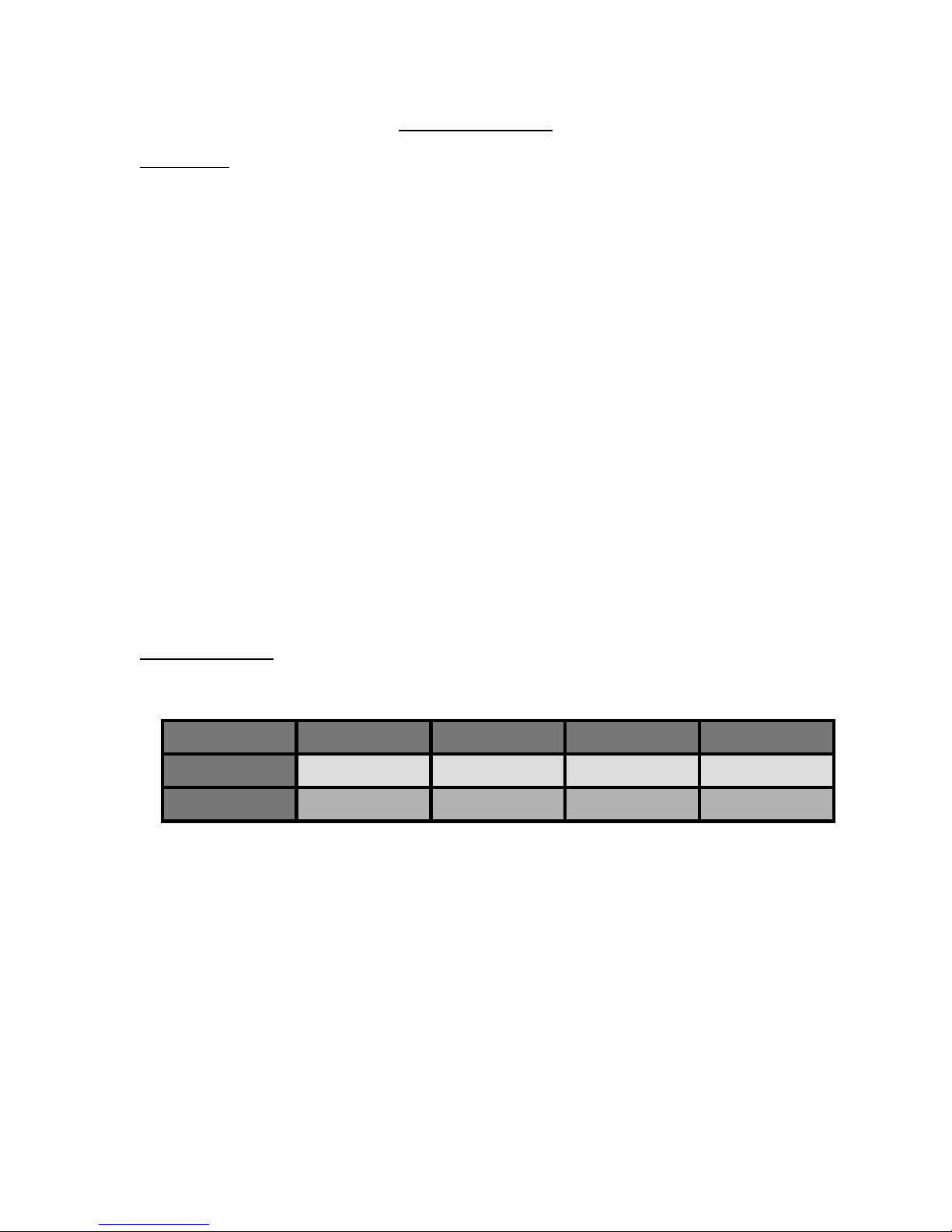
Model Amplifier Speakers Recline Color/Custom
Premium
Deluxe
---
Included
6
6
Power
Power
Colors
Color/Options
5
•Theater cable—twenty-five foot input cable with a ten pin connector on one end
and eight phono plugs on the other end to connect your home entertainment
equipment to the BodySound chair.
•Portable audio cable—audio input cable (a four foot cable with a 3.5mm stereo
male jack on each end)—this accessory cable is for devices such as portable CD
disc players, MP3 players, and laptops to make connections with the 3.5mm
audio input jack on the outer aspect of the left arm.
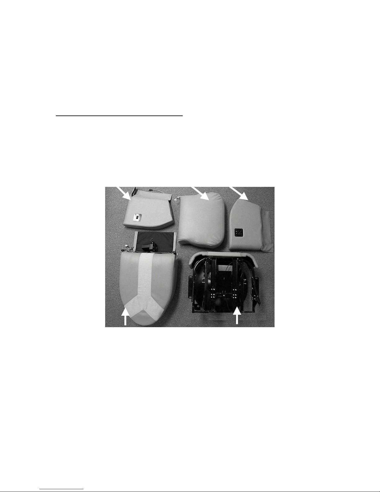
Assembly (Home Entertainment Chair):
The BodySound chair has been designed in modules to protect the enclosed
components during shipping and to enhance installation and serviceability. Assembly
should proceed as demonstrated after all of the components are removed from their
boxes.
Right Arm (Recline) Seat Left Arm (Amplifier)
Back Base
Review this process completely in the manual before beginning the assembly process.
Place the chair base in the desired location, checking to see that the front of the base is
centered so that it swivels 90 degrees to the left and to the right of the desired center
position.
If you are using a Theater cable, it should be routed from your entertainment equipment
underneath your carpeting, under the base of the chair, and out the exit hole in the neck
of the pedestal. It will be connected to the underside of the left arm after the left arm has
been attached to the seat frame. Allow enough slack in the cable hanging outside

6
the chair pedestal so that the chair can swivel full range without pulling on the
cable.
To prepare for laying the cables, mark the perimeter of the chair base after it has been
properly positioned in the room. Use masking tape to mark several positions around the
base. Move the base aside. Then mark the center point of the chair on the carpet. This
is the spot where you will make a slit about two inches long in the carpet, perpendicular
to the wall that you will be pulling the carpet back from. You may then pull the carpet
(and pad if desired) back from the wall to the spot where you cut the slit. Once the
cables have been installed, the carpet should be laid back down and the chair base
moved back to its specified location.
1. Back of the chair to seat frame:
a. Remove both detent pins from the two clevis joints on the back cushion.
See Figure 1.
b. Position the clevis joints of the back frame over the clevis joints of the seat frame
on both sides simultaneously (see Figure 2). Once they are in place insert the
detent pins from the inner aspect of the chair.
Figure 1 Back showing right and
left clevis joints with detent pins
in place.
Figure 2 Clevis joint on the back
frame fits around the clevis joint
of the seat frame.
7
c. To attach the power recline module to the seat frame, first remove the detent pin
that is currently positioned horizontally in two clearance holes at the bottom of
the bracket that supports the recline module (attached to the back of the seat
frame) by pulling on the metal ring. The chair back must be supported until the
recline motor is secured using this detent pin.
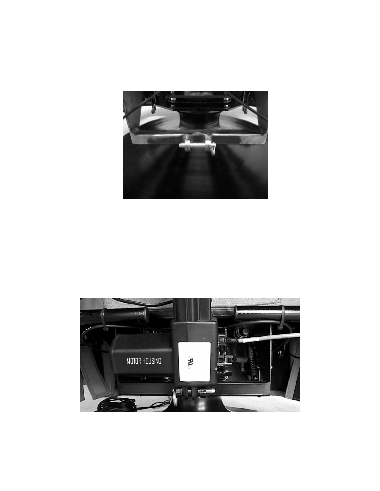
d. Position the recline motor with the motor housing facing left as you face the rear
of the chair. Make sure that you do not trap the power cable attached to the
recline motor underneath the recline motor housing. Position the clearance
holes at the bottom of the recline housing between the two clearance holes in the
metal recline support bracket on the seat frame. Move the chair back up or down
so that the clearance holes are aligned. Once positioned, reinsert the detent pin.
Jiggling the detent pin when applying pressure will allow for easier insertion.
Ensure that the detent pin is positioned through all the clearance holes.
Figure 3 Detent pin in place. Pull out
using the attached ring.
Figure 4 Detent pin extending through all of the holes in the
bracket and bottom of the recline motor. Note recline motor
housing facing to the left.

8
e. Cover the clevis joints with the clevis joint covers (see Figures 5 and 6).
2. Right arm to seat frame:
The right arm has the power recline switch which operates the power recline module.
The rounded end of the arm assembly faces towards the front of the chair. The
zipper is on the underside and back of the arm.
a. Remove both hand-bolts from the bottom of the right arm assembly.
b. Position the right arm assembly on top of the L-bracket (attached to the right
side of the seat frame—as if you are sitting in the chair). Ensure that the
power recline control cable is not caught between the arm assembly and the
seat frame. The cable exiting the right arm assembly should pass over the
seat frame and behind the metal frame that supports the clevis joint (see
Figure 7).
Figure 5a and 5b Clevis joint covers. Note the difference
between the right and left joint covers.
Figure 6 Clevis joint cover positioned over the clevis joint
and supporting metal frame. Close the cover with the
Velcro strips.

9
c. Position the right arm assembly so that the holes in the L-bracket of the seat
frame are aligned with the bolt holes in the bottom of the arm assembly.
Insert the bolts and hand-tighten securely but do not over-tighten (see Figure
8).
Figure 7 The right arm assembly is being held next to the right side of the chair to be placed on
the L-bracket. Note the recline control cable as it exits the right arm assembly and is positioned
properly over the back of the seat frame.
Figure 8 The right arm assembly is being held on top of the right side L-bracket and is
positioned properly so that the holes in the bottom of the arm assembly match the holes in the
L-bracket so that the hand-bolts can be inserted and tightened.
L-bracket
Recline
Control Cable

10
d. Connect the cable exiting from right arm assembly directly to the recline
motor.
e. Connect the recline power cable originating at the left rear of the seat frame
to the power cable attached to the front of the recline motor.
Figure 9 The recline control cable exiting the right arm connects
directly to the recline motor.
Figure 10 The recline power cable originating at the left rear of the seat
frame connects to the power cable attached to the recline motor.
11
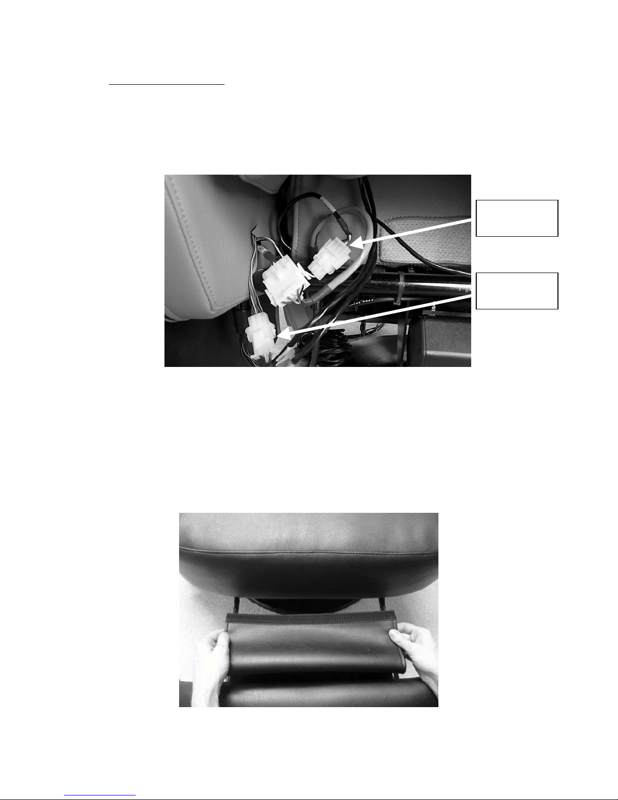
3. Seat pad to seat frame:
a. Position the seat pad on the seat frame so that the front of the seat pad
overhangs the front of the seat frame by about two inches. Ensure that the
speaker cable does not get caught underneath the pad or between the pad and
the chair back. The cable should rest on top of the back of the seat frame (see
Figure 11).
b. Extend the leg rest by pulling on the “D” ring located on the inner aspect of the
right arm next to the seat. You will notice a fabric flap attached to the leg rest at
one end with a Velcro strip on the free end. Secure the Velcro strip to Velcro strip
located on the underside of the seat pad that overhangs the frame (see Figures
12 and 13).
Figure 11 Speaker cables from the seat and back pad
positioned behind the seat pad.
Figure 12 Free end of the flap of material
attached to the leg rest.
Seat
(3 pin)
Back
(6 pin)

12
4. Left arm to seat frame:
The outer aspect of the left arm has a plate with an audio input connector,
headphone connector and fan grate if there is an amplifier contained within. The
rounded end of the arm assembly faces towards the front of the chair. The zipper is
on the underside and back of the assembly.
a. Remove both hand-bolts from the bottom of the left arm assembly.
b. Position the left arm assembly on top of the L-bracket (attached to the left side of
the seat frame—as if you are sitting in the chair). For chairs with an amplifier in
the left arm, ensure that the exiting cables are not caught between the arm
assembly and the seat frame. The cables should pass over the seat frame and
behind the metal frame that supports the clevis joint.
c. Position the left arm assembly so that the holes in the L-bracket of the seat frame
are aligned with the bolt holes in the bottom of the arm assembly. Insert the bolts
and hand-tighten securely but do not over-tighten.
If your chair does not have an amplifier enclosed in the left arm please proceed to
step 5.
d. Connect the two amplifier cables exiting from the left arm assembly to the
speaker cables exiting from the seat (3 pin) and back (6 pin) pads.
Figure 13 Completed attachment of the free end
of leg rest material to the bottom of the seat
cushion.

13
e. Connect the amplifier power cable exiting the left arm to the amplifier power
cable originating at the left rear of the seat frame.
5. Power supply and power supply cabling:
a. Turn the power supply switch off (“O”). Place the power supply near an AC outlet.
Figure 16 View of the power supply
with the AC plug attached and the
power supply switch turned off (0).
Figure 14 The seat (3 pin) and back (6 pin) speaker cables connect to the 3 and 6 pin amplifier
cables exiting the left arm.
Figure 15 The amplifier power cable (5 pin) connects to the 5 pin amplifier
p
ower cable ori
g
inatin
g
at the left rear of the seat frame.
Seat
(3 pin)
Back
(6 pin)

14
b. Plug the AC power cord into the power supply and then into the AC outlet.
c. Plug the DC power cord from the power supply into the chair receptacle located
on the underside of the chair at the left back section of the seat frame. Never
place the base of the chair on top of the DC power cable as this could cause the
cable to be cut.
Figure 17 Power supply plugged into an AC outlet
with the DC cable ready to be connected to the
BodySound chair.
Figure 18 DC power cable connected to the BodySound chair.

15
d. When you are ready to use your BodySound chair, turn the power supply switch
to on (“I”).
6. BodySound Chair Internal Cabling:
If your chair does not have an enclosed amplifier, then the speaker cables exiting
from the seat and back pads must be attached to an external amplifier in order to
drive the speakers. Alternatively, if your chair does have an enclosed amplifier and
you wish to drive the speakers from an external amplifier, you will also need
additional cabling. Wiring diagrams for the speaker cables can be requested from
BodySound Technologies, Inc. directly if needed.
Chair Operation:
Even without the amplifier and speakers, the BodySound chair has a number of
sophisticated mechanisms. It contains a swivel with 180 degrees of movement, near
horizontal power recline, extendable leg rest, and a heavy-duty, double-torsion, rocking
spring.
1. Power Recline:
Power recline operation:
The switch on the outer aspect of the right arm allows the back of the chair to be
placed in a more reclined or upright position.
•Pressing the switch downward will cause the back of the chair to move back
and down, assuming a more reclined position.
•Pressing the switch upward will cause the back of the chair to move forward
and up into a more upright position.
2. Leg Rest:
The leg rest release mechanism (“D” ring) is located between the right arm and the
seat pad towards the back. When you pull the release the leg rest will extend.
To close the leg rest, place pressure on it until it snaps shut.
3. Maintenance:
Every six months the following bolts should be checked for tightness:
Check and hand tighten the four hand-bolts securing the left and right arms to the
seat frame if necessary. If you can wiggle the arms in and out, then these bolts are
too loose.
16
Check to see that the detent pin that secures the lower end of the power recline
module to the bracket that supports the recline module is inserted through all holes.
If it is not then insert it through all three holes. See Figure 4.
The following bolts/nuts should only be tightened if they are loose.
To check these bolts/nuts you must remove the seat pad. To do so, carefully slide
the seat pad forward slightly to allow access to the seat speaker cable. Disconnect
the seat speaker cable from the seat amplifier cable. Release the leg rest and detach
the free end flap attached to the foot rest from the bottom of the seat pad. Now you
can remove the seat pad. After you have performed the following maintenance,
please follow step 3 in the assembly procedure to position the seat pad and
reconnect the seat speaker cable and free flap of the foot rest.
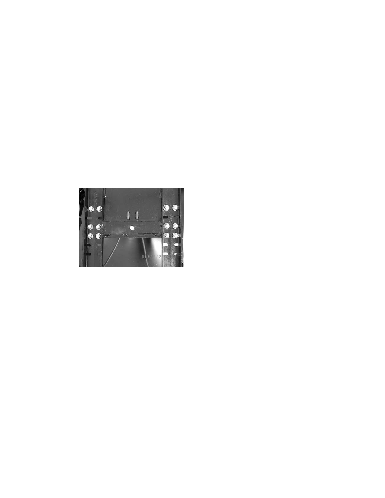
On the underside of the seat frame check visually and with your fingers to see
that there is no looseness of the six U-bolts (twelve nuts) that secure the free
ends of the double torsion spring to the seat base.
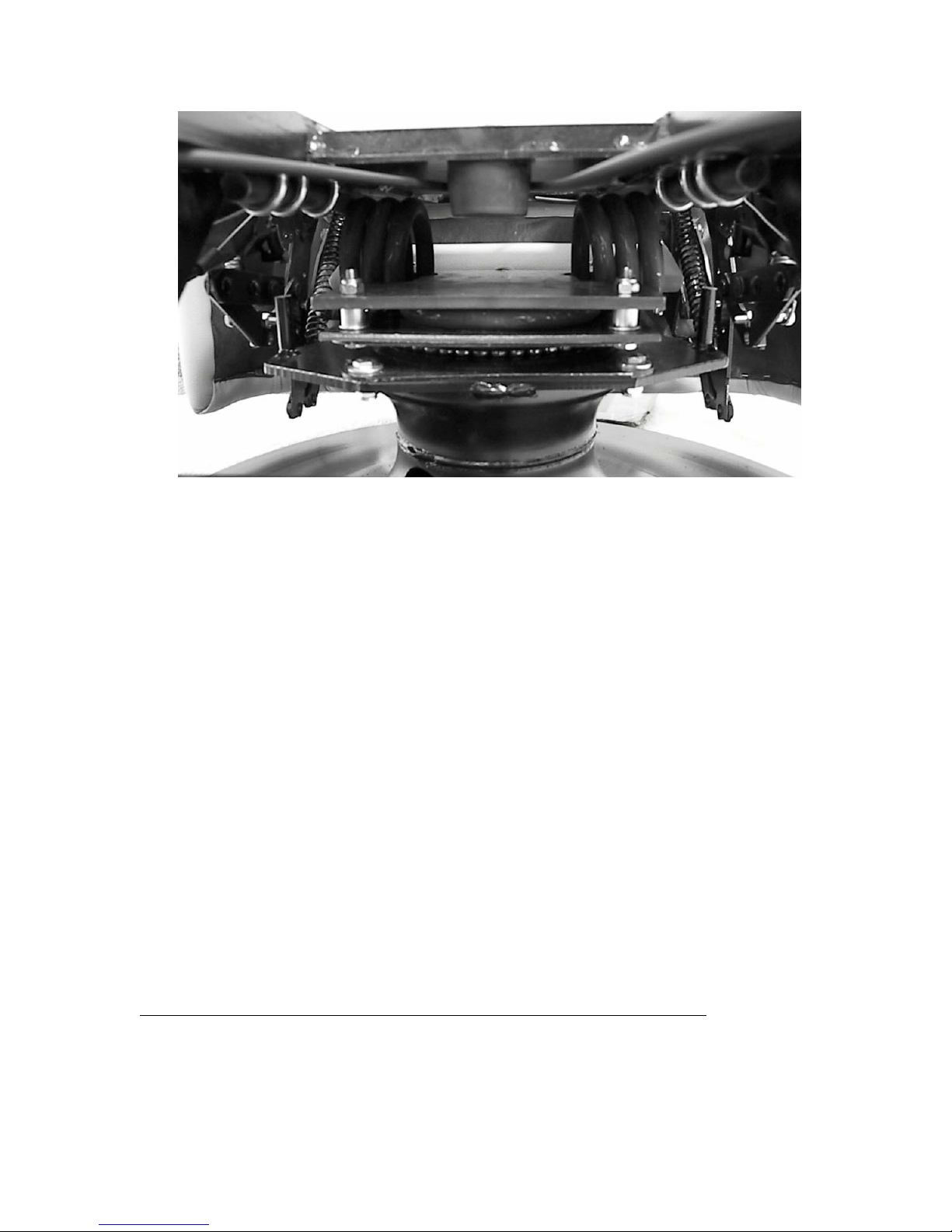
Check to see that there is no looseness in the four bolts that secure the torsion
spring retaining plate to the swivel plate and the four bolts that secure the swivel
plate to top of the pedestal. If any of these bolts are loose you may notice that
when you rock back or forward the back and seat portion of the chair will lean to
one side on the base (see Figure 20).
Figure 19 With the seat removed, visually inspect
the twelve nuts securing the six U-bolts. The six U-
bolts can be seen if you look on the underside of the
seat frame.
17
If there is any looseness of any of the twelve nuts that secure the six U-
bolts, the four bolts that secure the torsion spring retaining plate to the
swivel plate, or the four bolts that secure the swivel plate to the pedestal,
then tighten the loose bolts/nuts securely. Swivel the chair on the base
about 45 degrees to gain better access to the bolts and nuts attached to the
swivel plate as necessary.
BodySound Amplifier Operation:
The amplifier, when present, is contained within the left arm assembly. On the outer side
of the armrest there is a plate that supports one stereo 3.5mm audio input jack and one
headphone jack. Additional audio inputs are located on the bottom of the left arm. A
grate located below the audio input and headphone jacks on the outer side of the arm
allows the release of warm air from within the left arm assembly. There is a fan behind
the grate that blows air out. Cooler air is drawn up from the underside of the armrest. Do
not place anything under the armrest or against the fan grate that could block the
flow of air, as that could cause over-heating and damage to the amplifier. Do not
spray any liquids into the grate or the hole in the underside of the arm. Placing
any objects under either armrest could also impede the chair’s rocking motion
and cause damage to the arm assembly.
Audio Input Modes & Connections to Your Home Entertainment Equipment
There are three input modes that are selectable with your remote control. They are
Theater, Stereo, and Wireless. Depending upon how you connect the BodySound chair
to your home entertainment equipment you can play stereo music using any input mode,
but you can only have surround sound capability in Theater mode.
Figure 20 View from the back showing two bolts connecting the torsion spring retaining
plate to the top of the swivel plate and two bolts connecting the bottom of the swivel plate
to the pedestal.
18
To use Theater mode connect the twenty-five foot Theater cable to your equipment. It
has a ten pin connector on one end and four pairs of phono plugs on the other end. The
four pairs are labeled Head, Back, Seat, and Stereo. These phono plugs must be
inserted into the preamp outputs of your home entertainment equipment.
The recommended method of connection is as follows:
Preamp outputs on the back of Receiver Phono Plugs
Right and Left Surround channels Head (right & left)
Front Right and Left channels Back (right & left)
Center channel Seat (right OR left)
Subwoofer Optional Seat (right OR left)
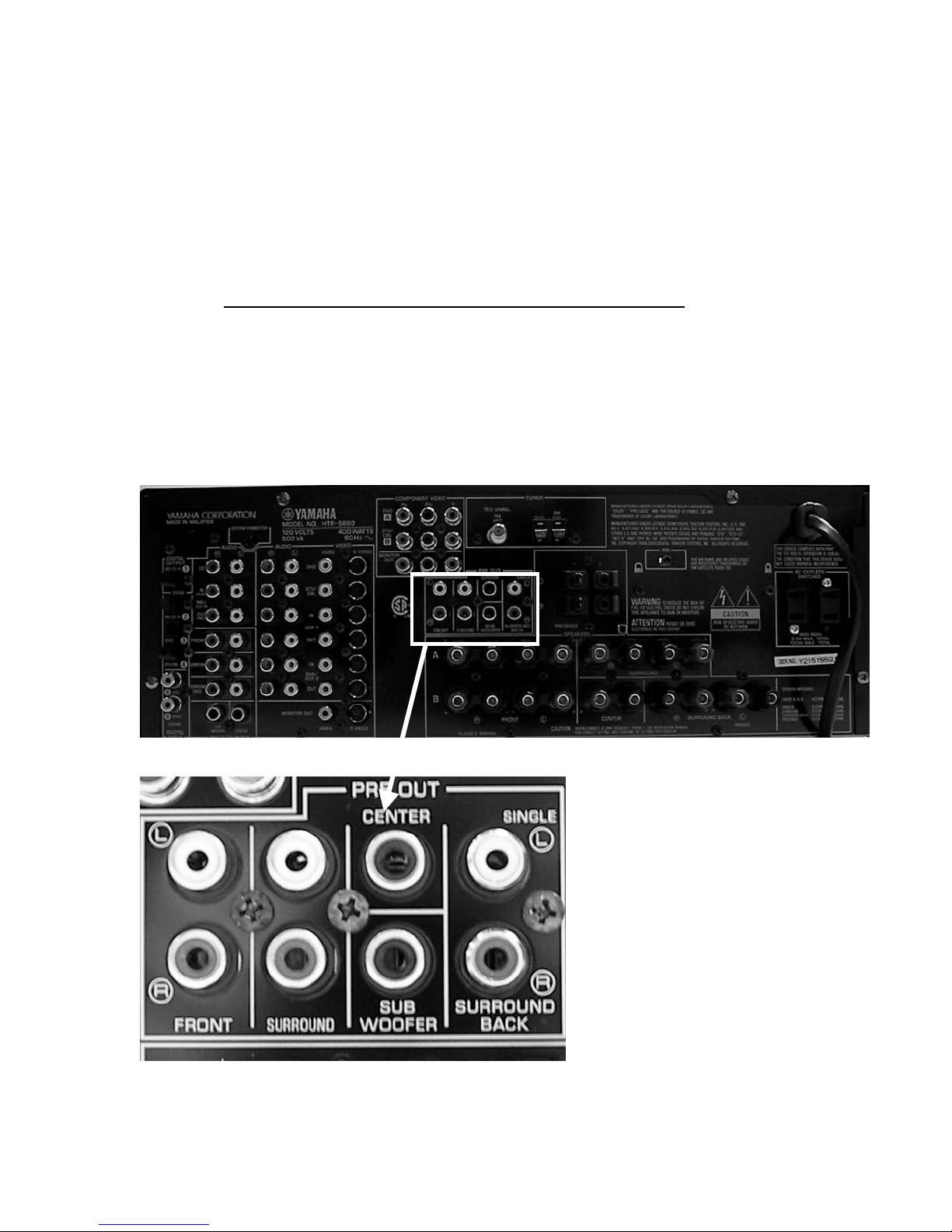
Figure 21 Component Pre-amp outputs from an
A
V Surround Receiver. The leftmost pair are
Front left (white) and right (red), the next pair
are left and right Surround and the Center
channel is the single jack above the Sub Woofer
j
ack. You do not need to connect to the
Surround Back outputs.

19
This configuration will maintain dialogue in front of you and surround effects behind you
consistent with your existing surround sound equipment.
Using these same connections you can play stereo music in Theater mode providing you
have your CD or DVD player hooked up to your surround receiver. Remain in Theater
mode and simply change the program or operating mode on your surround receiver to 7
channel stereo. That will send the stereo signals out the preamp connections that you
have already made. You can also watch TV in Theater mode by using the program

20
mode on your receiver that you use for movies or the 5 or 7 channel stereo mode if you
want to hear voices from the head speakers.
You may have noticed that there is also a pair of stereo phono plugs on the Theater
cable. We recommend that you plug those directly into the left and right preamp outputs
of whatever equipment you use to play CDs (Figure 22). That will typically be your DVD
or CD player. To use this connection select Stereo mode as your input setting using the
remote control. In this way you have the option of listening to music through the
BodySound chair while muting your surround sound equipment.
There is another stereo connection on the outside of the left arm that is designed
primarily for portable equipment (MP3 player, portable CD disc players, Laptop, etc.). A
four foot cable is provided that has a 3.5mm stereo plug on each end. When this 3.5mm
input jack is occupied, it will take precedence over the other wired stereo input (in the
theater cable).
A 5.8 GHz BodySound Wireless Transmitter (Figure 23) can also send stereo signals
directly to the built in wireless stereo receiver in the left arm. The wireless transmitter
must be connected to left and right stereo preamp outputs of the equipment playing the
audio source (receiver, DVD player, or TV). For the BodySound chair to use the wireless
stereo audio source, the user must select the Wireless mode as the Input setting using
the remote control.
Figure 23 BodySound Wireless Transmitter.
Figure 22 Stereo outputs labeled as R – Audio – L line out.
This manual suits for next models
1
Table of contents
Popular Indoor Furnishing manuals by other brands

Regency
Regency LWMS3015 Assembly instructions

Furniture of America
Furniture of America CM7751C Assembly instructions

Safavieh Furniture
Safavieh Furniture Estella CNS5731 manual

PLACES OF STYLE
PLACES OF STYLE Ovalfuss Assembly instruction

Trasman
Trasman 1138 Bo1 Assembly manual

Costway
Costway JV10856 manual


