Bodytastic L-10 User manual

1
L-10 Treadmill
Service Manual
V1.417

2
Table of Contents
Cover …………………………………………………………………………………………………………………………..1
Table of Contents …………………………………………………………………………………………………………2
Safety Information ……………………………………………………………………………………………………….3
Landice Warranty and Policies .......................................................................................4
Specifications……………………………………………………………………………………………………………….7
Electrical Schematic........................................................................................................8
Motor Pan
Components/Wiring.......................................................................................................9
Mini Pod Circuit Board/Wire Harness Pin designations……………………………………………….11
Mini Pod Servicing ………………………………………………………………………………………………………12
Error Codes/Troubleshooting……....................................................................................18
Display Optional
Settings/Information......................................................................................................22
Engineering Mode...........................................................................................................24
Parts Installation Removal
Motor Cover...................................................................................................................25
Rear Roller……….............................................................................................................25
Drive Roller....................................................................................................................26
Side Rail/Traction Strip...................................................................................................29
Deck………………...............................................................................................................30
Drive Motor……………………..............................................................................................32
Drive Belt……….…………...................................................................................................33
Shock Absorbers……...................................................................................................... 34
Treadbelt……………….......................................................................................................36
Incline Motor……………………………………........................................................................... 36
Calibrate Incline…………………………................................................................................. 37
Inverter........................................................................................................................ 38

3
Upright………………….......................................................................................................39
Maintenance………….......................................................................................................41
Safety Information
Safety Information -To reduce the risk of electric shock: always unplug the treadmill
from the electrical outlet immediately after using and before cleaning.
Always unplug the treadmill before cleaning or removing the motor cover.
Improper connection of the grounding connector can result in risk of electric shock.
Check with a qualified electrician/service technician if you are in doubt as to whether
the treadmill is properly grounded. Do not modify the plug provided with the
treadmill. If the plug will not fit in the outlet, have a proper electrical outlet installed
by a qualified electrician.
To reduce the risk of burns, fire, electric shock or injury to persons:
•An appliance should never be left unattended when plugged in. Unplug from outlet when not in
use, and before putting on or taking off parts.
•Close supervision is necessary when the treadmill is used by or near children or persons with
disabilities.
•Use the treadmill only for its intended use as described in this manual. Do not use attachments
not recommended by Landice.
•Never operate treadmill if it has a damaged cord or plug, if it is not working properly, or if it has
been damaged. Call your dealer or certified service provider immediately for examination and repair.
•Keep the power cord away from heated surfaces. Be sure the cord has plenty of slack and cannot
be pinched under the treadmill when it elevates and de-elevates.
•Never operate the treadmill with the motor cover air openings blocked. Keep the air openings free
of lint, hair, dust, or debris.
•Do not drop or insert objects into any opening on the treadmill. Be sure no objects are near or
beneath the treadbelt when you are using the treadmill.
•Do not use treadmill outdoors.
•Do not operate treadmill where aerosol (spray) products are being used or where oxygen is being
administered.

4
•To disconnect, press STOP twice, pull the safety lanyard out, then remove plug from outlet.
Grounding Instructions
Failure to observe the following warning
statements can result in serious injury!
•Do not use this product without first consulting
your doctor if you suffer from any illness,
condition, or disability that affects your ability to
run, walk or exercise.
•Do not use this product without supervision
present if you are suffering from any illness,
condition, or disability which affects your ability
to run, walk or exercise. Failure to do so can
result in serious injury should you fall while the
treadbelt is moving.
•Failure to leave ample clearance around the
treadmill could cause you to be trapped between
the treadmill and a wall if you fall, resulting in
burns or other serious injury from the moving
treadbelt. Allow a minimum clearance of 18
inches (46 cm) on each side of the treadmill.
Allow a minimum clearance of 6 feet (183 cm)
at the rear of the treadmill.
•Never stand on the treadbelt when starting
the treadmill. A sudden start could cause you to
lose your balance. Always begin by placing your
feet on the side traction strips, straddling the
treadbelt, before turning the treadmill on.
•Always wear the safety lanyard clip securely
on your clothing while exercising. Failure to do
so can result in severe injuries should you
accidentally fall while exercising.
•Test the emergency stop safety lanyard
regularly by pulling on the cord and ensuring that
the treadbelt comes to a complete stop when
key is pulled.

5
•Familiarize yourself with this manual. Be sure
you understand operation of the treadmill before
use.
•Always follow basic safety precautions when
using an electrical appliance.
Connect treadmill to a properly
grounded, dedicated electrical outlet
only. See the following Grounding
Instructions.
Do not plug treadmill into a surge
suppressor or Ground Fault Interrupt
(GFI) outlet.
Landice Warranty and Policies
If Treadmill is sold for use outside the USA then the International Warranty Applies
The Service Warranty covers installation of parts shown to be defective in material or
workmanship. The selling dealer is responsible for labor for product needing repairs. A Service
Authorization (SA) number must accompany any service reimbursement request. Service
Authorization numbers are given when the selling dealer or the service technician calls Landice
prior to beginning work on the product. This allows Landice to verify that the product is within
the labor warranty and also aids us in helping the technician troubleshoot the product. Landice
welcomes technicians to call us from the field and gives these calls the highest priority.
This Service Warranty does not cover customer instruction, installation, setup, maintenance, or
adjustments to treadbelt or drive belt.
Wear Item Warranty
1.CLUB Treadmills
Parts warranty for 5 years with unlimited hours with the exception of the treadbelt and deck
which are covered for 2 years and the headphone jack, connector and USB Port that have a 3
year warranty. CLUB treadmills are designed for heavy-duty commercial applications and any
pay-for-membership facilities.
This warranty does not cover cosmetic damage, damage due to acts of God, accident, misuse,
abuse, or negligence of the product. The part(s) will be covered in full only if it exhibits evidence
of a manufacturing or material defect during the warranty period. Please keep in mind,
“negligence of the product” includes damage inflicted by using the treadmill with an improperly
tracked treadbelt. This causes irreversible damage to the treadbelt edges and is not considered
a warranty issue.
Service Reimbursement Policy

6
This is offered to all Landice dealers as well as all authorized Landice service providers.
Landice covers our products with a 1-year labor reimbursement policy. That means we will pay
to fix our products as long as it's sold by the dealer within one year from the date the treadmill
was purchased by the dealer. After that date the product will carry only a 5 year parts warranty
and no labor.
Our Policy
Landice will reimburse the selling dealer according to our flat rate labor schedule of $80 per
issue. Note that treadbelt tracking, treadbelt / drive belt tensioning, blown fuses, and set-up
procedures are not covered by this warranty.
Set-Up Includes: Assembly, adjusting treadbelt and drive belt (if needed), walking the treadbelt
and deck wax in, and performing any additional adjustments that may have been upset during
shipping.
The Dealer/Service Provider must call for a Service Authorization (SA #) number prior to
performing any service to verify the treadmill is under labor warranty. Landice will also take this
opportunity to help troubleshoot the problem and, where possible, send the most likely part to
repair in one trip. Whenever possible it is advisable to call Landice from the product location to
successfully diagnose the problem.
Labor claim forms, supplied by Landice, must be submitted within three months from the date
service was performed. Labor claim forms must be completely filled out and have the Landice
Service Authorization number at the top. Generally service claims are paid out upon the return
of defective parts and/or crediting of the warranty invoice. If parts are outstanding for a period of
more than 90 days previously submitted service claims will be returned unpaid.
Floor Models And Dealer Stock
If the dealer sells a product to a customer within one year of its purchase from Landice, the
warranty period will be extended to start from the date of sale to the customer.
If a product is over 1 year old when sold to a customer, it will carry a 5 year parts warranty from
the date of shipment and there will be NO labor warranty.
Parts Policy
Our policy requires that all REQUESTED defective parts be returned to Landice. This will be
clearly marked on all packing slips and Invoices and an ARS tag to pay for its return will be
included with the part(s). If Landice does not need the parts back the packing slips and Invoices
will be clearly marked CREDIT. All warranty parts requiring return will be billed to the dealer at
dealer cost. Landice will credit this invoice upon receipt of defective parts. It is the dealer's
responsibility to return the defective parts to Landice with a copy of the invoice or packing slip. If
the defective parts are not returned within 30 days, payment of invoice is expected in full.
Warranty Part Ordering
When ordering parts under warranty please have the following information available. Warranty
orders cannot be processed without this information.
1) Customer's name, address and phone number

7
2) Serial number
3) Detailed description of failure
If the customer has not registered the product it will not have a warranty. No parts will be
sent and no Labor Claims will be paid unless the product is registered according to
Landice policy.
Purchase Part Ordering
Serial numbers are recommended to help ensure the correct part is shipped. Landice will not be
responsible for incorrect parts purchased. Purchased parts are covered by a 90 day
replacement part warranty from the date the order shipped. All parts purchases should be

8
L10-Club Treadmill Specifications
Model
L10
Display
Digital Display
Launch Date
Apr-2017
Mechanical Features
Drive Motor
5HP AC Drive
Voltage
220
Speed Range
0.5 - 15.5mph
Incline
0-15%
Treadbelt
22" x 60"
Frame Material
Steel
Deck
1" Reversible
Roller
3 1/2"
Cross Bar Controls
Yes
Side Rails
Yes
Fan
Yes
Heart Rate
Yes
(Contact Heart Rate - Read Only)
Accessory Pockets
Phone, tablet and 2 water bottles holders
Step-up Height from Floor to Treadbelt
9"
Electrical Requirement
220 volt, 50/60Hz, 10 amps w/ Dedicated Line
Max User Weight
500 lbs.
Product Weight
460lb
Shipping Weight
600lb
Dimensions
83" x 34" x 64"
Warranty
10 Year - Frame
5 Year - Parts
2 Year - Wear Items (deck & belt)
90 days - High Wear Items (USB port)
1 Year Labor
Certifications
UL, CAN, CE
Console
CSAFE Jack
Yes
(External on the side of display)
TV
Bracket with BVE TV (Optional)
Coaxial cable or HDMI jack located on upright leg
USB Port
Yes
(Charging capability )

9
Electrical Schematic

10
Motor Pan Components-
Inverter- Wiring
1. From Inverter to Display
2. From Inverter to Elevation Motor
3. From Filter to Inverter. Black and Red wires power the Inverter.
4. From Inverter to Drive Motor

11
Mini Pod
Mini Pod Pin/wire harness designations on L10 and 90 series Treads
The 12 pin minipod connector pinout:
Pin1 GND1 (Output) Ground
Pin2 P0.0 (Input) Speed Up Switch
Pin3 P0.1 (Input) Speed Down Switch and Stop Switch
Pin4 P0.2 (Input) Incline Up Switch and Start Switch
Pin5 P0.3 (Input) Incline Down Switch
Pin6 P2.70 (Output) Switch Common for Speed and Incline Switches
Pin7 P2.40 (Output) Switch Common for Start and Stop Switches
Pin8 +5VF (Output) 5 Volt power for Heart Rate boards
Pin9 CEO (Input) CE Safety switch
Pin10 INT1 (Input) Heart Rate from Wireless
Pin11 Pulse (Input) Heart Rate from Handgrips
Pin12 GND (Output) Ground

12
Pins 2-7 are for reading switches, Pins 1, 8, and 12 are power pins, Pin 9 is safety key, and pins 10 and 11
are the two heart rate inputs.
13
Servicing the MiniPod– L10 and 90 SERIES
Tools Required- Medium and small Philips screwdriver
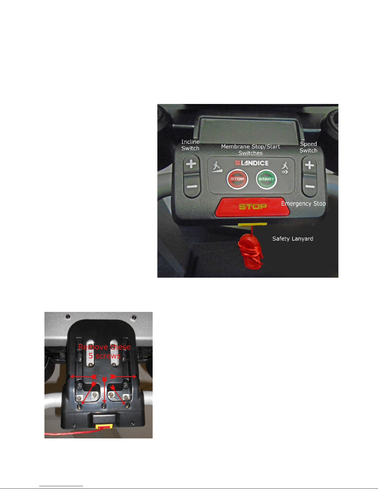
Front of POD –Labelled Components
How to remove Pod from frame- The Pod is held on with 5 screws. Remove screws and Pod will come
off.(Bottom view)

14
How to open Mini Pod to gain access to internal components.
It is not necessary to remove Pod to change most components. Remove the four screws holding the Pod
together.
Pod will split into two halves-

15
How to remove Elevation or Speed Switches- Remove cable from Circuit board and four
screws from switch assembly- Entire switch will come out-Note-Only three pins are used,
leave GND1 open.
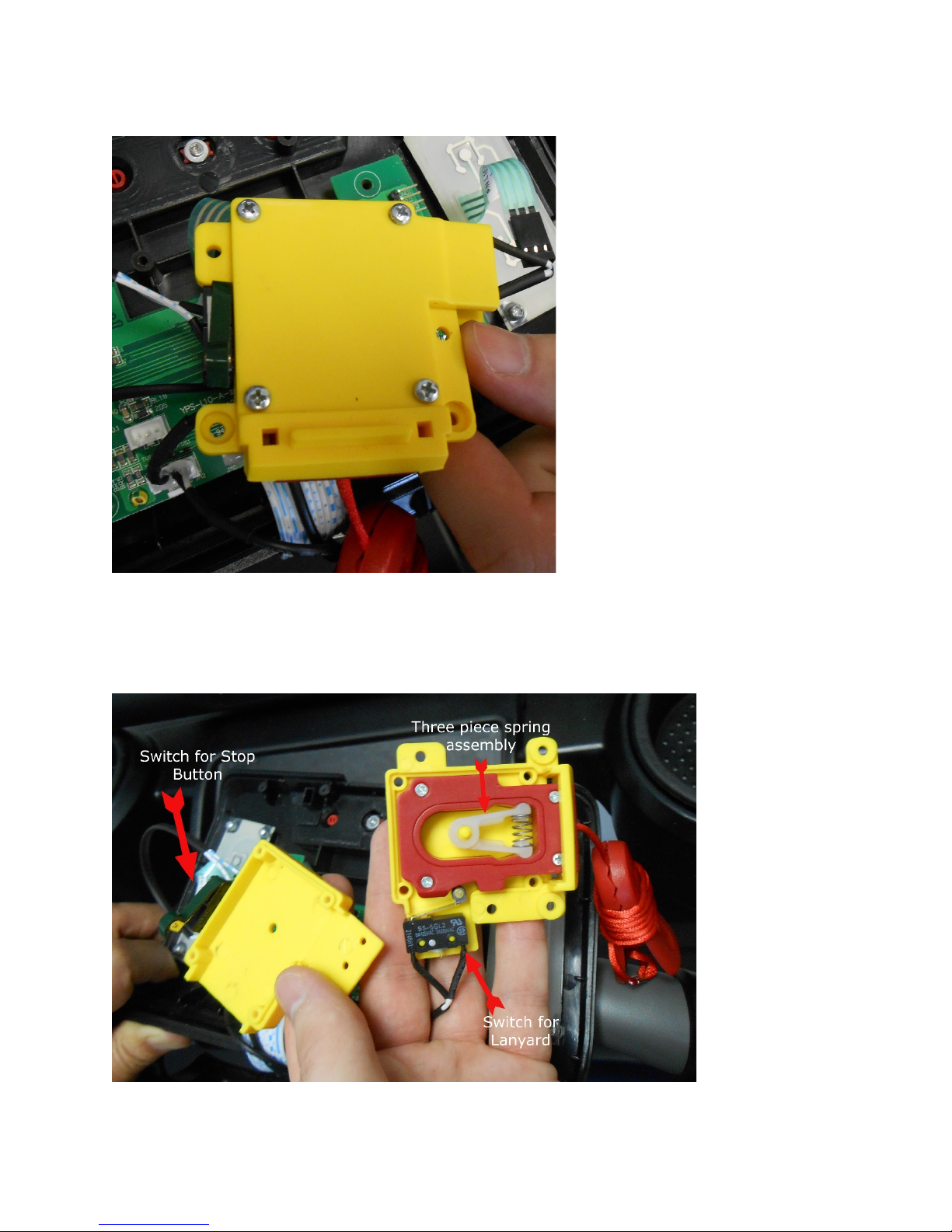
How to remove Safety System- Remove four screws holding the Safety System housing
together
16
Remove Four Screws from back of Safety Switch Housing-
Inside Safety Switch Assembly

17
Remove Spring Assembly by squeezing together. Remove four screws to gain access to Safety
Lanyard string
Remove Circuit Board /Membrane- Disconnect switches for Speed/Incline (note empty pin-
only three are used, GND1 remains open), safety switches, both contact and wireless heart
rate, and membrane (note only three pins are used). Do not remove white ribbon cable that
goes to the upper display. That must be detached from the connector cable inside the display
console. Remove four screws holding the circuit board and remove board.

18

19
Error Code Diagnostics for the L10 Treadmill
Note: A log of recent error codes is found in Engineering Mode
1.) ER01 – Communication Error
Communication disruption between the inverter and the upper
control board:
The inverter sends a signal to the upper control board every
1.5 seconds to check to see if they are still in
communication with each other. If no response, the
inverter shuts the AC motor down.
The code CE10 appears on the display after the
communication is reestablished
The potential reasons for the communication disruption could be:
A faulty display board
A faulty inverter
Faulty cabling
2) ER02 – Incline Motor Error
Whatever the voltage is coming into the inverter is the
same voltage going to the incline motor
The voltage across the pot is detected:
The Delta inverter detects the voltage across the pot via
feedback through connector J12 PIN2. The voltage (0 to
5volts) corresponds to a value between 0 and 32767 in
address location 2251h. Impulse should test the incline
motor when developing the L10 to know the upper limit
and downward limit and determine what value corresponds
to what value in location 2251h.
Then console gives a value to inverter then the inverter
makes the incline motor go to the target position and stop
when the actual position value in location 2251h reaches
the command value.
The potential reasons for the communication disruption could be:
A faulty elevation motor
A faulty pot
Faulty limit switch(es)
Faulty cabling
3) ER03 – Safety Key/Replace Safety Key

20
The Upper display board monitors the safety circuit and
flags this condition when the safety is pulled. Always check
that the safety key is pressed in before proceeding.
Potential reasons for this error are:
Faulty Safety circuit
Faulty cabling
Faulty Display Board
4) ER04 – (Also OL) AC Motor Over-Current Error
The inverter monitors the AC motor in order to determine
the amount of over current
It also monitors the amount of time that the current is over
the maximum limit
The standard maximum limit is 150% of the rated current of
the motor (which for the Kuo Shuay motors the rating is 7
amps). For the error code (OL) to come up, the motor
would have to be in over loaded for over 60 seconds. The
inverter would then shut down the AC drive motor.
The potential reasons for an AC motor over-current condition
could be:
Failure of one or more of the internal motor components
(bearings, rotor, stator windings, etc.)
Excessive load on the AC drive motor putting excessive
loading onto the motor (Friction in the belt and deck, bad
roller bearing, etc.)
Note- A Heavy Person walking at slow speeds may cause
this error due to the extra load. The same is true for a
heavy person who is running at high speeds.
5) ER05 – AC Motor Voltage Error
AC Motor voltage monitoring
The inverter can monitor the motor voltage and determine if
its receiving too much or too little voltage
The potential reasons for an AC motor low or high voltage:
Inverter malfunctioning
City voltage too low or too high
6) ER06 – AC Motor Over Load Error
The display will show ER06 when the AC motor’s thermal sensor
pops
Table of contents


