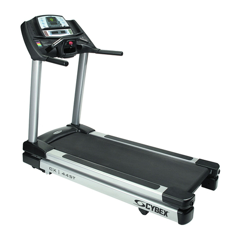
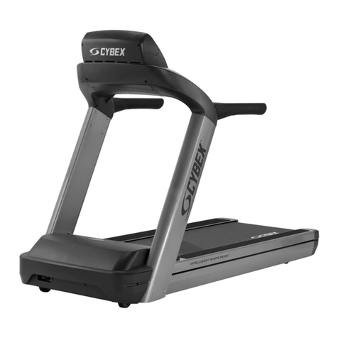
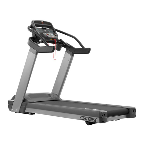
CYBEX V Series User manual

Cybex - V Series Treadmill
Assembly Instructions
Part Number
1018092-0001 AA


Corporate Headquarters
10601 W Belmont Ave, Franklin Park, IL 60131 • U.S.A.
847.288.3300 • FAX: 847.288.3703
Service phone number: 800.351.3737 (toll-free within U.S.A., Canada)
Global Website: www.cybexintl.com
International Oices
AMERICAS
North America
Cybex International Inc.
10601 W Belmont Ave
Franklin Park, IL 60131 U.S.A.
Telephone: (847) 288 3300
Service Email: [email protected]om
Sales/Marketing Email:
commercialsales@lifefitness.com
United Kingdom
Life Fitness UK LTD
Queen Adelaide
Ely, Cambs, CB7 4UB
Telephone: General Oice (+44) 1353.666017
Customer Support (+44) 1353.665507
Service Email: [email protected]
Sales/Marketing Email: life@lifefitness.com
All Other EMEA Countries and Distributor Business EMEA*
Bijdorpplein 25-31
2992 LB Barendrecht
THE NETHERLANDS
Telephone: (+31) 180 646 644
Service Email: EMEAService[email protected]
Brazil
Life Fitness Brasil
Av. Rebouças, 2315
Pinheiros
São Paulo, SP 05401-300
BRAZIL
SAC: 0800 773 8282 option 2
Telephone: +55 (11) 3095 5200 option 2
Service Email: [email protected]om
Sales/Marketing Email: vendasbr@lifefitness.com
Germany, Austria, and Switzerland
Life Fitness Europe GMBH
Neuhofweg 9
85716 Unterschleißheim
GERMANY
Telephone:
+49 (0) 89 / 31775166 Germany
+43 (0) 1 / 6157198 Austria
+41 (0) 848 / 000901 Switzerland
Service Email: [email protected]om
Sales/Marketing Email: vertrieb@lifefitness.com
ASIA PACIFIC (AP)
Japan
Life Fitness Japan, Ltd
4-17-33 Minami Aoyama 1F/B1F
Minato-ku - Tokyo 107-0062
Japan
Telephone: (+81) 0120.114.482
Fax: (+81) 03-5770-5059
Service Email: service.lfj@lifefitness.com
Sales/Marketing Email: sales@lifefitnessjapan.com
Latin America and Caribbean*
Life Fitness, LLC
10601 W Belmont Ave
Franklin Park, IL 60131 U.S.A.
Telephone: (847) 288 3300
Service Email: [email protected]om
Sales/Marketing Email:
commercialsales@lifefitness.com
Spain
Life Fitness IBERIA
C/Frederic Mompou 5,1º1ª
08960 Sant Just Desvern Barcelona
SPAIN
Telephone: (+34) 93.672.4660
Service Email: servicio.tecnico@lifefitness.com
Sales/Marketing Email: info[email protected]
Hong Kong
Life Fitness Asia Pacific LTD
32/F, Global Trade Square
21 Wong Chuk Hang Road
Hong Kong
Telephone: (+852) 2575.6262
Service Email: Service.HK@lifefitness.com
Sales/Marketing Email: hongkong.sales@lifefitness.com
EUROPE, MIDDLE EAST, and AFRICA (EMEA)
Netherlands and Luxemburg
Life Fitness Atlantic BV
Bijdorpplein 25-31
2992 LB Barendrecht
THE NETHERLANDS
Telephone: (+31) 180 646 666
Service Email: service.benelux@lifefitness.com
Sales/Marketing Email:
marketing.benelux@lifefitness.com
Belgium
Life Fitness Benelux NV
Parc Industrial de Petit-Rechain
4800 Verviers
BELGIUM
Telephone: (+32) 87 300 942
Service Email: service.benelux@lifefitness.com
Sales/Marketing Email:
marketing.benelux@lifefitness.com
All Other Asia Pacific countries and distributor business Asia
Pacific*
32/F, Global Trade Square
21 Wong Chuk Hang Road
Hong Kong
Telephone: (+852) 2575.6262
Fax: (+852) 2575.6894
Service Email: Service.AP@lifefitness.com
Sales/Marketing Email:
Marketing.HK.Asia@lifefitness.com
*Also check www.cybexintl.com for local representation or distributor/dealer
Page 1 of 28

User and Service Documents Link
https://lifefitness9512.zendesk.com/hc/en-us
https://lfworld.lifefitness.com
Additional information is available online using the links above.
.
点击上面的链接可在线获取更多信息。
Flere oplysninger er tilgængelige online gennem linket ovenfor.
Bijkomende informatie is online beschikbaar via bovenstaande link.
Vous trouverez plus d'informations en ligne à l'aide du lien ci-dessus.
Zusätzliche Informationen finden Sie online über den oben angegebenen Link.
Ulteriori informazioni sono disponibili online utilizzando il link sopra riportato.
追加情報は上記リンクを使用してオンラインで利用可能です。
상기 링크를 통해 온라인에서 추가 정보를 볼 수 있습니다.
Informações adicionais estão disponíveis on-line, através do link acima.
Дополнительная информация доступна в интернете по ссылке, указанной выше.
Mediante el enlace anterior podrá acceder a información adicional en línea.
Ytterligare information finns online genom att använda länken ovan.
İnternet daha fazla bağlantıyı
.
Informazio osagarria eskuragarri dago goiko estekaren bidez.
Допълнителна информация можете да намерите онлайн, като използвате връзката по-горе.
Mitjançant l'enllaç anterior podreu accedir a informació addicional en línia.
使用上面的連結線上提供額外資訊。
Dodatne informacije možete pronaći na internetu sljedeći vezu iznad.
ከላይ የተቀመጠውን አገናኝ(ሊንክ) በመጠቀም መረጃዎች ኦንላይን ያገኛሉ
Lisätietoja on saatavissa verkosta käyttämällä yllä olevaa linkkiä.
Wubetumi anya nsɛm afoforo aka ho wɔ wɛbsait so denam asɛm a ɛwɔ atifi hɔ a wubemia so so.
Πρόσθετες πληροφορίες είναι διαθέσιμες ονλάιν χρησιμοποιώντας το σύνδεσμο παραπάνω.
.עדימ ףסונ רשפא לבקל טנרטניאב תועצמאב רושיקה ליעל
További információ elérhető online, a fenti hivatkozás segítségével.
Viðbótarupplýsingar eru fáanlegar á netinu með því að smella á tengilinn hér fyrir ofan.
Plus indicium per superum situm potes invenire.
.
Ytterligere informasjon er tilgjengelig på nettet via linken ovenfor.
Dodatkowe informacje są dostępne online pod powyższym odnośnikiem.
Informações adicionais estão disponíveis online a usar o link acima.
Informații suplimentare sunt disponibile online, utilizând link-ul de mai sus.
Dodatne informacije dostupne su na mreži putem gornjeg linka.
Ďalšie informácie sú dostupné online na vyššie uvedenom odkaze.
Page 2 of 28

Table of Contents
Getting Started
Safety Instructions.........................................................................................................................................................................................................4
Set-Up.............................................................................................................................................................................................................................. 6
Product Overview
Product Features........................................................................................................................................................................................................... 9
Mounting and Dismounting the Treadmill............................................................................................................................................................... 9
User Position.................................................................................................................................................................................................................. 9
Using and Testing the Emergency Stop System......................................................................................................................................................9
Assembly
Component and Hardware List................................................................................................................................................................................10
Tools Required.............................................................................................................................................................................................................11
Remove Motor Cover.................................................................................................................................................................................................. 11
Install Uprights.............................................................................................................................................................................................................12
Install Front Crossbar..................................................................................................................................................................................................13
Install Bridge.................................................................................................................................................................................................................14
Tighten Upper Hardware........................................................................................................................................................................................... 15
Tighten Lower Hardware........................................................................................................................................................................................... 15
Install Console Cables and Grommets....................................................................................................................................................................16
Install Upper Dashboard Tray................................................................................................................................................................................... 17
Install Console............................................................................................................................................................................................................. 17
Console Connections................................................................................................................................................................................................. 18
Install Lower Dashboard Tray................................................................................................................................................................................... 18
Install Rear End Caps..................................................................................................................................................................................................18
Install Motor Cover......................................................................................................................................................................................................19
Install Front End Caps................................................................................................................................................................................................ 19
Install Power Cord....................................................................................................................................................................................................... 19
Service and Technical Data
Preventive Maintenance Schedule.......................................................................................................................................................................... 21
Preventive Maintenance Tips....................................................................................................................................................................................21
Approved and Compatible Cleaners....................................................................................................................................................................... 22
Troubleshooting the Treadmill.................................................................................................................................................................................22
How to Obtain Product Service................................................................................................................................................................................23
How to Adjust and Tension the Striding Belt.........................................................................................................................................................24
Belt Tensioning Bolts..................................................................................................................................................................................................24
Tracking (Centering) A Striding Belt........................................................................................................................................................................ 24
Tensioning an Existing Striding Belt........................................................................................................................................................................24
Specifications
Specifications...............................................................................................................................................................................................................26
Cybex® and the Cybex logo are registered trademarks of Cybex International, Inc.
DISCLAIMER: Cybex International, Inc. makes no representations or warranties regarding the contents of this manual. We reserve the right to revise this
document at any time or to make changes to the product described within it without notice or obligation to notify any person of such revisions or
changes.
© Copyright 2021, Life Fitness, LLC. All Rights Reserved. Life Fitness, Hammer Strength, Cybex, ICG and SCIFIT are registered trademarks of Life Fitness,
LLC and its companies and subsidiaries. Brunswick and related trademarks used under license from Brunswick Corporation. Disclaimer: Images
and specifications are current as of the date of publication and are subject to change.
10601 W Belmont Ave, Franklin Park, IL 60131 • 800-351-3737 • 847-288-3700 •
www.cybexintl.com • 1018092-0001 AA • 2021
Page 3 of 28

Getting Started
Safety Instructions
Read all instructions before use.
CAUTION: Any changes or modifications to this equipment could void the product warranty.
CAUTION: Risk of injury to persons – to avoid injury, use extreme caution when stepping onto or o of a moving belt. Read
assembly instruction manual before using.
WARNING: Health-related injuries may result from incorrect or excessive use of exercise equipment. Life Fitness Family of
Brands STRONGLY recommends seeing a physician for a complete medical exam before undertaking an exercise program,
particularly if the user has a family history of high blood pressure or heart disease, is over the age of 45, smokes, has high
cholesterol, is obese, or has not exercised regularly in the past year. If, at any time while exercising, the user experiences
faintness, dizziness, pain, or shortness of breath, he or she must stop immediately.
WARNING: To reduce the risk of burns, fire, electric shock, or injury, it is imperative to connect each product to a properly
grounded electrical outlet.
WARNING: Heart rate monitoring systems may be inaccurate. Over exercising may result in serious injury or death. If you feel
faint, stop exercising immediately.
WARNING: Do not use for stretching and do not attach straps or other devices.
WARNING: Keep batteries out of reach of children.
Some chest straps may contain a removable battery.
• Swallowing may lead to serious injury in as little as 2 hours or death, due to chemical burns and potential perforation of
the esophagus.
• If you suspect your child has swallowed a battery, immediately call your local poison control for fast, expert advice.
• Examine devices and make sure the battery compartment is correctly secured, e.g. that the screw or other mechanical
fastener is tightened. Do not use if compartment is not secure.
• Dispose of used button batteries immediately and safely. Flat batteries can still be dangerous.
• Tell others about the risk associated with button batteries and how to keep their children safe.
WARNING: Keep the area 6.5 . (2 m) by 3 . (0.9 m) behind the treadmill clear of any obstructions, including walls, furniture,
and other equipment. Contact Customer Support Services for an optional longer power cord if necessary.
WARNING: Be sure the emergency stop lanyard is clipped to the user and in proper position on the treadmill before beginning
any workout.
WARNING: The belt centering adjustment must be performed if the belt is not between the marks indicating the maximum
allowed lateral positions. Refer to Treadmill Assembly Instructions.
WARNING: This product can expose you to chemicals including Acrylonitrile, which is known to the State of California to
cause cancer and birth defects or other reproductive harm. For more information go to http://www.P65Warnings.ca.gov
DANGER: To reduce the risk of electrical shock or injury from moving parts, always unplug product before cleaning or
attempting any maintenance activity.
• Never operate the product if it has a damaged power cord or electrical plug, or if it has been dropped, damaged, or even partially
immersed in water. Contact Customer Support Services.
• Position the product so that the power cord plug to the wall is accessible to the user. Make sure that the power cord is not knotted
or twisted and that it is not trapped under any equipment or other objects.
• If the electrical supply cord is damaged, it must be replaced by the manufacturer, an authorized service agent, or a similarly
qualified person to avoid a hazard.
• Always follow the console instructions for proper operation.
• This appliance is not intended for use by persons (including children) with reduced physical, sensory, or mental capabilities, or lack
of experience or knowledge unless they have supervision or been given instruction concerning the use of the appliance by a person
responsible for their safety.
• Do not use this product outdoors, near swimming pools or in areas of high humidity.
• Never operate the product with the air openings blocked. Keep air openings free of lint, hair, or any other obstructing material.
• Never insert objects into any opening in these products. If an object should drop inside, turn o the power, unplug the power cord
from the outlet, and carefully retrieve it. If the item cannot be reached, contact Customer Support Services.
• Never place liquids of any type directly on the unit, except in an accessory tray or holder. Containers with lids are recommended.
Page 4 of 28
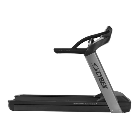

• Do not use these products in bare feet. Always wear shoes. Wear shoes with rubber or high-traction soles. Do not use shoes with
heels, leather soles, cleats or spikes. Make sure no stones are embedded in the soles.
• Keep all loose clothing, shoelaces, and towels away from moving parts.
• Do not reach into, or underneath, the unit or tip it on its side during operation.
• This equipment is not intended for use by children. Keep children under the age of 14 away from the machine.
• Do not allow other people to interfere in any way with the user or equipment during a workout.
• Allow LCD consoles to “normalize” with respect to temperature for one hour before plugging the unit in and using.
• The product should never be le unattended when plugged in. Disconnect from the electrical outlet when not in use, and before
putting on or taking o parts. To disconnect, turn power OFF at the ON/OFF switch, then remove plug from electrical outlet.
• Keep the power cord away from heated surfaces. Do not pull the equipment by the power cord or use the cord as a handle. Do not
run the power cord on the floor under or along the side of the treadmill.
• Handrails may be held to enhance stability as needed, but are not for continuous use.
• Never mount or dismount the treadmill while the running belt is moving. Use the handrails whenever additional stability is
required. In case of an emergency, such as tripping, grasp the handrails, and place the feet on the side platforms.
• Never walk or jog backwards on the treadmill.
• Do not use this product in areas where aerosol spray products are being used or where oxygen is being administered. Such
substances create the danger of combustion and explosion.
• Use these products for their intended use as described in this manual. Do not use attachments that have not been recommended
by the manufacturer.
• In conformity with the European Union Machinery Directive 2006/42/EC, this equipment unloaded runs at sound pressure levels
below 70 dB (A) at the average operating speed of 12 km/hr (commercial units) and 8 km/hr (home units). Noise emission under
load is higher than without load.
• Free standing equipment shall be installed on a stable and leveled surface.
• Read all warnings on each product prior to starting a workout.
• If warnings are missing or damaged, please contact Customer Support Services immediately for replacement warning labels.
Warning labels are shipped with every product and should be installed before product is used. Life Fitness is not responsible for
missing or damaged warning labels.
Page 5 of 28

Set-Up
Read the entire manual before setting up the treadmill. Place the treadmill where it will be used before beginning the setup procedure.
Electrical Power Requirements
The treadmill requires a dedicated* line with isolated neutral according to the electrical configurations listed in the chart below.
Supply Voltage (VAC) Frequency (Hz) Rated Current (Amps)
100 50 / 60 18
120 50 / 60 18
200 50 / 60 9
220 50 / 60 9
230 50 / 60 9
240+ 50 / 60 9
* One individual branch circuit for each treadmill per NEC article 210-21 (b) (1) and 210-22 (or other appropriate, country specific
electrical compliance guidelines). The hot and neutral wires must each be routed independently (not looped or tied to other circuits).
NOTE: Do not modify the plug provided with this product. If the plug does not fit into an available electrical outlet, have a proper
outlet installed by a qualified electrician.
Grounding Instructions
This product must be properly grounded. If the unit malfunctions or breaks down, proper grounding provides a path of least resistance
for the electric current, which reduces the risk of shock to anyone touching or using the equipment. Each unit is equipped with an
electrical cord, which includes an equipment grounding conductor and a grounding plug. The plug must be inserted into an outlet
that has been properly installed and grounded in accordance with all local codes and ordinances.
WARNING: A temporary adapter MUST NOT BE USED to connect this plug to a two-pole receptacle in North America. If a
properly grounded, 20-amp outlet is not available, one must be installed by a qualified electrician. Models drawing 16 amps or
more must be installed on a dedicated line. (Commercial Units Only).
DANGER: A risk of electrical shock may result from improper connection of the equipment-grounding conductor. Check with a
qualified electrician if in doubt as to proper grounding technique. DO NOT modify the plug provided with the product. If it will
not fit an electrical outlet, have a proper outlet installed by a qualified electrician. Any modification to the electrical plug will
result in a voided warranty.
Page 6 of 28

How to Position and Stabilize the Treadmill
Follow all safety instructions. Move the treadmill to the location in which it will be used.
NOTE: See How to Adjust and Tension the Striding Belt to center the striding belt.
Safety Clearances
The following information is supplied as regional reference data regarding safety clearances around the exterior of the treadmill.
•EU: The European EN ISO 20957 Safety Standard requires a 6.5 . (2 m) minimum from the rear of the treadmill to any object or
surface and at least as wide as the treadmill.
•U.S. and other regions: The ASTM International (ASTM ) F2115 - 12 Standard recommends the minimum dimensions to be 1.64 .
(0.5 m) on each side of the treadmill and 6.5 . (2 m) behind the rearward most portion of the usable moving surface or 6.5 . (2 m)
behind the furthest rearward obstruction to emergency egress from the treadmill.
Free area
1 6.5 . (2.0m)
2 1.64 . (0.5m)
Aer placing the unit where it will be used, check its stability. If there is even a slight rocking motion or the unit is not stable, determine
which stabilizing leg is not resting on the floor. To adjust, loosen the Jam Nut, and turn the Stabilizing Leg until the rocking motion
ceases, and both stabilizing legs rest firmly on the floor. Re tighten the Jam Nut.
Item Description Qty.
1 Jam Nut 2
2 Stabilizing Leg 2
NOTE: Stabilize the treadmill each time the unit is relocated.
NOTE: It is extremely important that the stabilizing leg be correctly adjusted for proper operation. An unbalanced unit may cause
striding belt misalignment. A bubble level is recommended to ensure proper leveling.
Page 7 of 28

Power Switch
Located on the front panel at the base of the treadmill, the ON/OFF switch has two positions: "I" (one) for ON and "0" (zero) for OFF.
Power Cord Routing
WARNING: Make sure the power cord is unplugged before attempting to route it around or through the treadmill.
Connect the power cord to the power receptacle in the front of the treadmill. The power cord can be run to the user-front le or right
sides depending on installation / site needs.
NOTE: To accommodate treadmill incline, at least 2 . (24”) of power cord is required between the outlet and the last power cord clip
for outlets in front of the treadmill.
WARNING: Keep the area 6.5 . (2 m) by 3 . (0.9 m) behind the treadmill clear of any obstructions, including walls, furniture,
and other equipment. Contact Customer Support Services for an optional longer power cord if necessary.
DANGER: Ensure that the power cord does not contact the striding belt or get pinched between the frame, li arm or under
the wheels; failure to follow this warning may result in serious injury.
Item Description
1 Power Receptacle
2 Frame
3 Wheel
4Li Arm
5 Striding Belt
Immobilization Method
The purpose of immobilizing the treadmill is to prevent unauthorized use. The system causes immobilization of the treadmill when a
pre-defined hard key sequence has been activated.
1. Set the display to read SELECT WORKOUT.
NOTE: Press the CLEAR key twice if not already there
2. Hold down the SPEED DOWN key and press the PAUSE key.
The treadmill now displays IMMOBILIZED. In this state, the treadmill cannot be operated. The belt and incline motors are disabled. The
treadmill will remain in this state across resets, power cycles, etc. To restore normal operation, repeat the same key sequence; hold
down the SPEED DOWN key, and press the PAUSE key. The treadmill will display SELECT WORKOUT again.
Page 8 of 28

Product Overview
Product Features
Item Description
1 Console
2 Cup Holders
3 Emergency Stop Lanyard
4 Contact Heart Rate Sensors
5 Handrails
6 Striding Belt
Mounting and Dismounting the Treadmill
Use the handrails to enhance stability when mounting or dismounting a treadmill. Never mount or dismount the treadmill while the
running belt is moving. Use the STOP button on the console to end a workout and stop the running belt. Use the Emergency Stop
System to stop the belt immediately.
User Position
The width of the moving walking/running surface is 20 in. (51 cm). Users must keep their feet within this width while in motion. If
standing on the stationary side rails, a user should ensure that his/her feet are completely on the non-moving portion. Never step
partially on the moving surface and partially on the non-moving surface simultaneously.
• Users can adjust their fore-a position on the moving belt as desired for reach to the console and handles, clearance for arm swing
and attachment of the safety stop pull cord. Do not step on the rear roller.
• It is recommended that the user run within the length of the side handrails to allow usage of the side arms to dismount the belt if
needed.
Using and Testing the Emergency Stop System
The treadmill is equipped with an Emergency Stop System. The system consists of a rectangular stop magnet (located on the upper
bridge plastic) attached to a safety stop pull cord.
Before starting a workout, attach the lanyard on the safety stop pull cord to an item of the user's clothing. During a workout, pull the
cord to remove the magnet from the bridge. This will immediately stop the treadmill belt.
NOTE: Test the safety stop pull cord by attaching the lanyard to a user's item of clothing during operation of the treadmill. While the
treadmill is on and the console display is active, remove the safety stop pull cord / magnet from the bridge. A message will be
displayed on the console similar to "Replace the emergency stop switch". With the safety stop pull cord removed no keys shall function
on the treadmill. Place the safety stop pull cord back in place. The treadmill will reset and will be ready for operation.
Page 9 of 28

Assembly
Component and Hardware List
Components
Item Description Qty
1Le Upright 1
2 Right Upright 1
3 Ergo™ Front Crossbar 1
4 Upper Dashboard Tray 1
5 Lower Dashboard Tray 1
6 Console 1
7 End Cap Front 2
8 End Cap Rear 2
9 Bridge 1
10 Ergo™ Bar Backing Plate 2
11 Cable Tie 2
Hardware
Item Description Qty
1 Bolt, 3/8 x 5” Hex Head 8
2 Washer, 3/8” Flat 8
3 Lock Nut, 3/8” 6
4 Bolt, M8 x 20mm Hex Head 8
5 Washer, M8 12
6 Lock Nut, M8 8
7 Plastic Grommet 2
8 Screw, M4.2 x 19mm Phillips Head 14
9 Screw, M5 x 25mm Phillips Head 4
10 Screw, #10 x 0.5” Phillips Head (silver) 2
11 Screw, #10 x 0.5” Phillips Head (black) 2
Page 10 of 28

Tools Required
• Phillips screwdriver
• 9/16" Wrench (2)
• 9/16" Socket 3/8" Drive
• 13 mm Socket
• 13 mm Wrench
• 3" Extension 3/8" Drive
• 3/8” Drive ratchet
Remove Motor Cover
1. Remove screws securing motor cover to base assembly using a Phillips screwdriver.
Item Description Qty
1 Motor Cover 1
2 Base Assembly 1
3 Screw, M4.2 x 19mm Phillips Head 4
2. Remove motor cover.
Page 11 of 28

Install Uprights
1. Place uprights on base assembly.
2. Install one bolt, washer, and lock nut to le and right upright and base assembly using a 9/16" socket and wrench.
Item Description Qty
1Le Upright 1
2 Right Upright 1
3 Bolt, 3/8 x 5” Hex Head 2
4 Washer, 3/8” Flat 2
5 Lock Nut, 3/8" 2
NOTE: Leave a spacing of 5-12mm between washer and upright.
3. Align uprights with holes in base assembly.
4. Install bolts, washers, and lock nuts securing uprights to base assembly using a 9/16" socket and wrench.
Item Description Qty
1 Bolt, 3/8 x 5” Hex Head 6
2 Washer, 3/8” Flat 6
3 Lock Nut, 3/8" 4
Page 12 of 28

Install Front Crossbar
1. Route cable from front crossbar into le upright.
Item Description Qty
1 Ergo™ Front Crossbar 1
2. Install bolts, washers, and lock nuts securing front crossbar to uprights using a 13mm socket and wrench.
Item Description Qty
1 Lock Nut, M8 4
2 Washer, M8 4
3 Bolt, M8 x 20mm Hex Head 4
Page 13 of 28

Install Bridge
1. Install a bolt, washers, and lock nut to each upright using a 13mm socket and wrench.
Item Description Qty
1 Upright 2
2 Lock Nut, M8 2
3 Washer, M8 4
4 Bolt, M8 x 20mm Hex Head 2
NOTE: Leave a spacing of 5-12mm between washer and upright.
2. Slide bridge down uprights.
Item Description Qty
1 Bridge 1
2 Upright 2
Page 14 of 28
3. Install bolts, washers, and lock nuts securing the bridge to uprights using a 13mm socket and wrench.
Item Description Qty
1 Bridge 1
2 Upright 2
3 Lock Nut, M8 2
4 Washer, M8 4
5 Bolt, M8 x 20mm Hex Head 2
Tighten Upper Hardware
Tighten hardware 100%.
Item Description Qty
1 Bolt, M8 x 20mm Hex Head 8
Tighten Lower Hardware
Tighten hardware 100%.
Item Description Qty
1 Bolt, 3/8 x 5” Hex Head 8
Page 15 of 28

Install Console Cables and Grommets
NOTE: TV cables (Coax and power) are included in every treadmill with or without TV option. They must be routed up through le
upright and stored in dashboard.
1. Route TV cables (Coax and power) up through le upright and into dashboard area.
Item Description Qty
1 Coax Cable 1
2 Power Cable 1
3 TV Cables are Coiled and Stored Here 1
4 External Coax Cable Connection 1
5 Access Hole for Cables 1
2. Route console cable up through le upright.
3. Install plastic grommets to front crossbar.
Item Description Qty
1 Plastic Grommet 2
2 Cable Tie 2
3 Console Cable 1
4 TV Cables (Coax and Power) 1
NOTE: For international units, install the ferrite approximately 7 inches from the center of the bridge. Route console cable through
ferrite and secure with cable tie.
Item Description Qty
1 Ferrite 1
2 Cable Tie 1
3 Console Cable 1
Page 16 of 28
4. Secure cables from front crossbar and le upright to the bridge using cable ties.
Install Upper Dashboard Tray
1. Install screws securing bar backing plate to front crossbar using a Phillips screwdriver.
Item Description Qty
1 Ergo™ Bar Backing Plate 2
2 Screw, #10 x 0.5” Phillips Head (black) 2
2. Install screws securing upper dashboard tray to front crossbar using a Phillips screwdriver.
Item Description Qty
1 Upper Dashboard Tray 1
2 Screw, M4.2 x 19mm Phillips Head 2
NOTE: Be careful not to over tighten screws. Over tightening can damage the plastic.
Install Console
1. Install screws securing console to upper dashboard tray using a Phillips screwdriver.
Item Description Qty
1 Console 1
2 Screw, M5 x 25mm Phillips Head 4
2. Connect cables.
Page 17 of 28
Console Connections
Item Description Qty.
1 Display Connection 1
Install Lower Dashboard Tray
Install screws securing lower dashboard tray to upper dashboard tray using a Phillips screwdriver.
Item Description Qty
1 Lower Dashboard Tray 1
2 Screw, M4.2 x 19mm Phillips Head 4
3 Screw, #10 x 0.5” Phillips Head (silver) 2
Install Rear End Caps
Install screws securing rear end caps to base assembly using a Phillips screwdriver.
Item Description Qty
1 Rear End Cap 2
2 Screw, M4.2 x 19mm Phillips Head 4
Page 18 of 28
Other manuals for V Series
5
Table of contents
Other CYBEX Treadmill manuals

CYBEX
CYBEX Treadmill Application guide

CYBEX
CYBEX 625T User manual

CYBEX
CYBEX CardioTouch 770T User manual

CYBEX
CYBEX PRO3 User manual

CYBEX
CYBEX 600T User manual

CYBEX
CYBEX 700T Application guide

CYBEX
CYBEX Pro+ User manual

CYBEX
CYBEX LCX-425T User manual

CYBEX
CYBEX 700T Application guide

CYBEX
CYBEX 770T-CT User manual
Popular Treadmill manuals by other brands

Life Fitness
Life Fitness 9100HR Quick manual

Pro-Form
Pro-Form 3.9 Xm Treadmill Bedienungsanleitung

Pro-Form
Pro-Form CROSSWALK 325 Bedienungsanleitung

HEALTH RIDER
HEALTH RIDER SoftStrider EX user manual

Star Trac
Star Trac 4-TR Service manual

Life Fitness
Life Fitness PLATINUM CLUB SERIES Assembly instructions