BodyTrain HC108A User manual
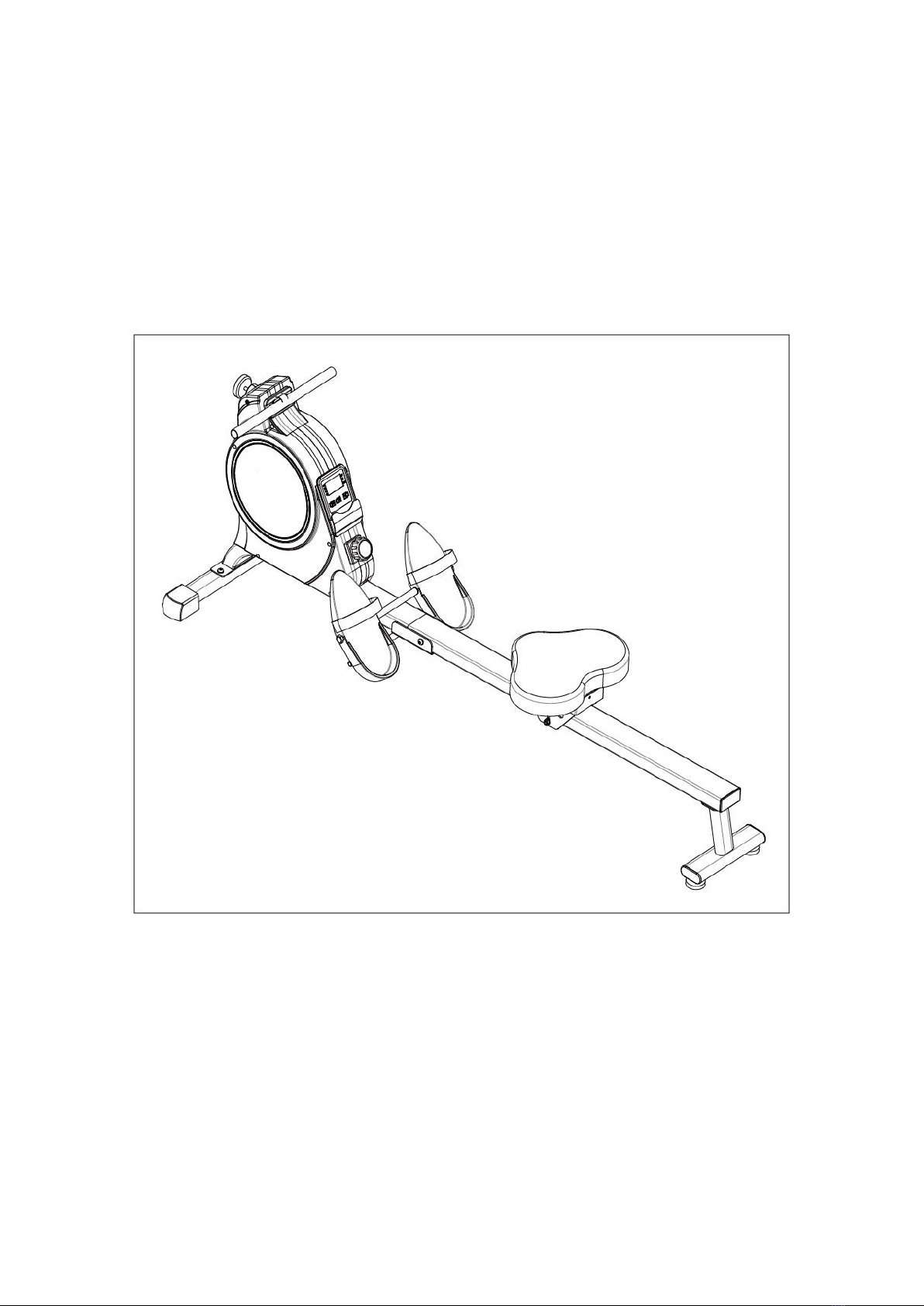
MAGNETIC ROWING MACHINE
HC108A
USER MANUAL
IMPORTANT! Please retain owner’s manual for maintenance and adjustment instructions. Your
satisfaction is very important to us.

1
IMPORTANT SAFETY INFORMATION
We thank you for choosing our product. To ensure your safety and health, please use this
equipment correctly. It is important to read this entire manual before assembling and using the
equipment. Safe and effective use can only be achieved if the equipment is assembled, maintained,
and used properly. It is your responsibility to ensure that all users of the equipment are informed of
all warnings and precautions.
1. Before starting any exercise program, you should consult your physician to determine if you
have any medical or physical conditions that could put your health and safety at risk or prevent
you from using the equipment properly. Your physician’s advice is essential if you are taking
medication that affects your heart rate, blood pressure, or cholesterol level.
2. Be aware of your body’s signals. Incorrect or excessive exercise can damage your health. Stop
exercising if you experience any of the following symptoms: pain, tightness in your chest,
irregular heartbeat, shortness of breath, lightheadedness, dizziness, or feelings if nausea. If you
do experience any of these conditions, you should consult your physician before continuing with
your exercise program.
3. Keep children and pets away from the equipment. The equipment is designed for adult use only.
4. Use the equipment on a solid, flat level surface with a protective cover for your floor or carpet.
To ensure safety, the equipment should have at least 2 feet (60 CM) of free space all around it.
5. Ensure that all nuts and bolts are securely tightened before using the equipment. The safety of
the equipment can only be maintained if it is regularly examined for damage and/or wear and
tear.
6. Always use the equipment as indicated. If you find any defective components while assembling
or checking the equipment, or if you hear any unusual noises coming from the equipment during
exercise, discontinue use of the equipment immediately and do not use until the problem has
been rectified.
7. Wear suitable clothing while using the equipment. Avoid wearing loose clothing that may
become entangled in the equipment.
8. Do not place fingers or objects into the moving parts of the equipment.
9. The maximum weight capacity of this unit is 285 pounds (130 KG).
10.The equipment is not suitable for therapeutic use.
11.To avoid bodily injury and/or damage to the product or property, proper lifting and moving are
required.
12.Your product is intended for use in cool and dry conditions. You should avoid storage in extreme
cold, hot or damp areas as this may lead to corrosion and other related problems.
13.This equipment is designed for indoor and home use only; it is not intended for commercial use
2
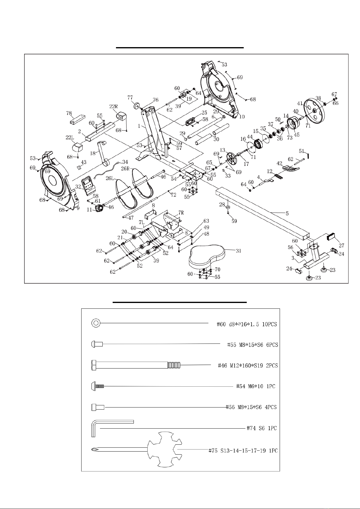
EXPLODED DIAGRAM
HARDWARE PACKAGE

3
PARTS LIST
No.
Description
Spec.
QTY
No.
Description
Spec.
QTY
1
Main Frame
1
34
Sensor Wire
L370
1
2
Front Stabilizer
1
35
Bearing
Φ35*Φ10*11
1
3
Rear Support
1
36
Bearing
Φ30*Φ17*7
2
4
Magnet Frame
1
37
Bearing
35*17*16
1
5
Sliding Rail
1
38
Bearing
Φ26*Φ10*8
1
6
Handlebar
1
39
Bearing
Φ22*Φ8*7
8
7L/R
Seat Supporting
L/R
2
40
Bearing Steel
Φ17*46
1
8
U Shape Bracket
2
41
Inertial Wheel
Φ240*25 2.5kg
1
9
Chain Cover L
1
42
Magnet
25*10*5 2800
7
10
Chain Cover R
1
43
Inductor Seat
1
11
Tension Control
Knob
L=210
1
44
Volute Spring
t0.5*22*5080
1
12
Plastic Lattice
Magnet
27*7
1
45
Axle Sleeve
Φ42*44.5
1
13
Volute Spring
Cover
118.5*11.8
1
46
Bolt
M12*160*S19
2
14
Mesh Belt Wheel
Φ35*110
1
47
Fixing Axle for Pedal
Φ12*440
1
15
Outer PC Board
Φ89*Φ16.5*0.5
1
48
Adjusting Screw
M6 L45
2
16
PC Board
Φ111*Φ16*0.5
1
49
U Shape Baffle
30*10*1.5 2
2
17
Axle for Mesh Belt
Wheel
Φ22*133
1
50
Fixing Axle for Mesh
Belt
Φ5*43
1
18
Mesh Belt
t1.5*22*2150
1
51
Spring
Φ0.8*Φ8*60 65MN
1
19
Mesh Belt Pulley
POM Φ42*Φ22*32
1
52
Spacer
D8*Φ15*4
6
20
Wheel
Φ40*92 POM
3
53
Screw
M5*8
3
21
Casing Pipe for
Idler Wheel
Φ13*Φ8*78 ABS
3
54
Screw
M6*10
1
22L/R
End Cap
30*60
2
55
Screw
M8*15*S6
12
23
Foot Leveler
M8
2
56
Screw
M8*15*S6
4
24
End Cap
70*30
2
57
Nut
M6
1
25
Handlebar Seat
104*50*18 PVC
1
58
Screw
M5*15
3
26L/R
Pedal L/R
320*140*55
2
59
Screw
M6*20
2
27
End Cap
40*80*1.5
1
60
Washer
d8*Φ16 *1.5
24
28
Rubber Buffer
Φ25.2*Φ22*15
1
61
Washer
Φ20*Φ5*1.0
1
29
End Cap
Φ25*1.5 PVC
2
62
Bolt
M8*125*15 *S14 A
5
30
Foam Grip
180
2
63
Nut
M6*H6*S10
2
31
Seat
1
64
Nut
M8*H7.5*S13
5
32
Computer
1
65
Nut
M10*1.0 H5
1
33
Magnet
Φ11*3
1
66
Nut
M10*1.0 H3
1

4
No.
Description
Spec.
QTY
No.
Description
Spec.
QTY
67
Nut
M10*1*H8*S14
2
73
C-clip
d36
1
68
Screw
ST4.2*20*Φ8
6
74
Allen Wrench
S6
1
69
Screw
ST4.2*16*Φ8
10
75
Spanner
S13-14-15-17-19
1
70
Spring Washer
Φ8
4
76
Nut
M8
1
71
Wave Washer
d10*Φ15*0.3
2
77
Foot Leveler
M8*35 PVC
1
72
C-clip
d12
1
78
Shipping Tube
1
Table of contents


