Boffin My Home II User manual

All kits and manuals are available at www.boffin.cz/en
Overview: Amendments of the new EN 62115: 2020/A11:2020 concerning batteries and LEDs
Batteries
Small batteries
Batteries that fit wholly within the small parts cylinder
(as specified in §8.2 of EN 71- 1:2014+A1:2018) shall not
be removable without the aid of a tool.
For parts of electric toys containing batteries, where the
part fits wholly within the small parts cylinder (as specified
in 8.2 of EN 71-1:2014+A1:2018), batteries shall not be
accessible withoutthe aid of a tool.
Other batteries
Batteries shall not be removable without the aid of a tool
unless the security of the battery compartment cover is
adequate.
Compliance is checked by inspection and by the following
test. An attempt is made to gain access to the battery
compartment by manual means. It shall not be possible
to open the cover unless at least two independent
movements have to be applied simultaneously.
The electric toy is placed on a horizontal steel surface.
A cylindrical metallic mass of 1 kg, having a diameter of
80 mm, is dropped from a height of 100 mm so that its flat
face falls onto the electric toy. The test is carried out once
with the cylindrical metallic mass striking the electric toy
in the most unfavourable place. The battery compartment
shall not become open.
So all batteries need a battery cover in future, which
complies with the specifications above.
Batteries supplied with the toy
Primary batteries supplied with electric toys shall comply
with the relevant parts of the IEC 60086 series.
A Pass Test Report is needed.
Secondary batteries supplied with electric toys shall
comply with IEC 62133.
A Pass Test Report is needed.
Battery compartment fasteners
If srews or similar fasteners are used to secure a door or
cover providing access to the battery compartment, the
srew or similar fastener shall be captive to ensure that
they remain with the door, cover or equipment.
Compliance is checked by inspection and by the following
test after the battery door or cover is opened. A force of
20N is applied to the srew or similar fastener without jerks
for a duration of 10s in any direction.
The srew or similar fastener shall not become seperated
from the door, cover or equipment.
Light-emitting diodes
The emission from electric toys incorporating LEDs
shall not exceed the following limits:
– 0,01 Wm-2 when assessed at 10 mm from the LED
front for accessible emissions with wavelengths
of < 315 nm;
– 0,01 Wsr-1 or 0,25 Wm-2 when assessed at 200 mm,
for accessible emissions with wavelengths of 315 nm
≤λ< 400 nm;
– 0,04 Wsr-1 or the AEL specified in Tables E.2 or E.3
assessed at 200 mm for accessible emissions with
wavelengths of 400 nm ≤λ< 780 nm;
– 0,64 Wsr-1 or 16 Wm-2 when assessed at 200 mm
for accessible emissions with wavelengths of 780 mm
≤λ< 1 000 nm;
– 0,32 Wsr-1 or 8 Wm-2 when assessed at 200 mm
for accessible emissions with wavelengths of 1 000 nm
≤λ< 3 000 nm.
LED data sheets
As the technical data sheet is essential for compliance
with this standard, it shall be developed following the
measurement criteria of condition A or condition B of CIE
127. The technical data sheet shall indicate that it has
been created using the CIE 127 measurement methods
and as a minimum include:
– the luminous intensity in candela or radiant intensity
in Watts per steradian as a function of forward current,
– the angle,
– the peak wavelength,
– the spectral emission bandwidth,
– the date of issue and the revision number.
So all LEDs need a LED data sheet in future,
which includes the specifications above.
WARNING: This toy produces flashes that may trigger epilepsy in sensitised
individuals.
Only for use by children aged 8 years and older. Not suitable for children and under 8 years
due to small parts which could cause a choking hazard.
WARNING! Hot surface, do not touch bulb.
Flash frequency
Light bulb warning

INTRODUCTION TO ELECTRICITY 3-6
ELECTRICITY IN OUR WORLD 7-8
AS ELECTRICITY ENTERS YOUR HOME 9-11
12
13-50
51-53
54
55-57
58
59-60
61
62
Project Listings
Projects 1 - 34
How To Use Your Boffin
Parts List
About Your Boffin Parts
DO’s and DON’Ts of Building Circuits
Troubleshooting
Notes
SC- MyH7 Parts Layout
A Note to Parents and Adults:
Because children’s abilities vary
so much, even with age groups,
adults should exercise discretion
as to which experiments are
suitable and safe (the instructions
should enable supervising adults
to establish the experiment’s
suitability for the child). Make sure
your child reads and follows all
of the relevant instructions and
safety procedures, and keeps
them at hand for reference.
This product is intended for use
by adults and children who have
attained sufcient maturity to
read and follow directions and
warnings.
Never modify your parts, as doing
so may disable important safety
features in them, and could put
your child at risk of injury.
Table of Contents
CAUTION: The lamp (L4) has a very warm lamp enclosure.
S
N
A
P
P
Y
A
N
D
F
R
I
E
N
D
S
Not responsible for typographical errors.
Welcome to the World of Boffin
- Never connect Boffin
to the electrical outlets in your home in any way.
3
INTRODUCTION TO ELECTRICITY
1.In this manual, sometimes we say “house” or “building” or “home”. Whether you live in a city skyscraper, apartment building, townhouse,
or farmhouse in the country - it doesn’t matter - electricity works the same way!
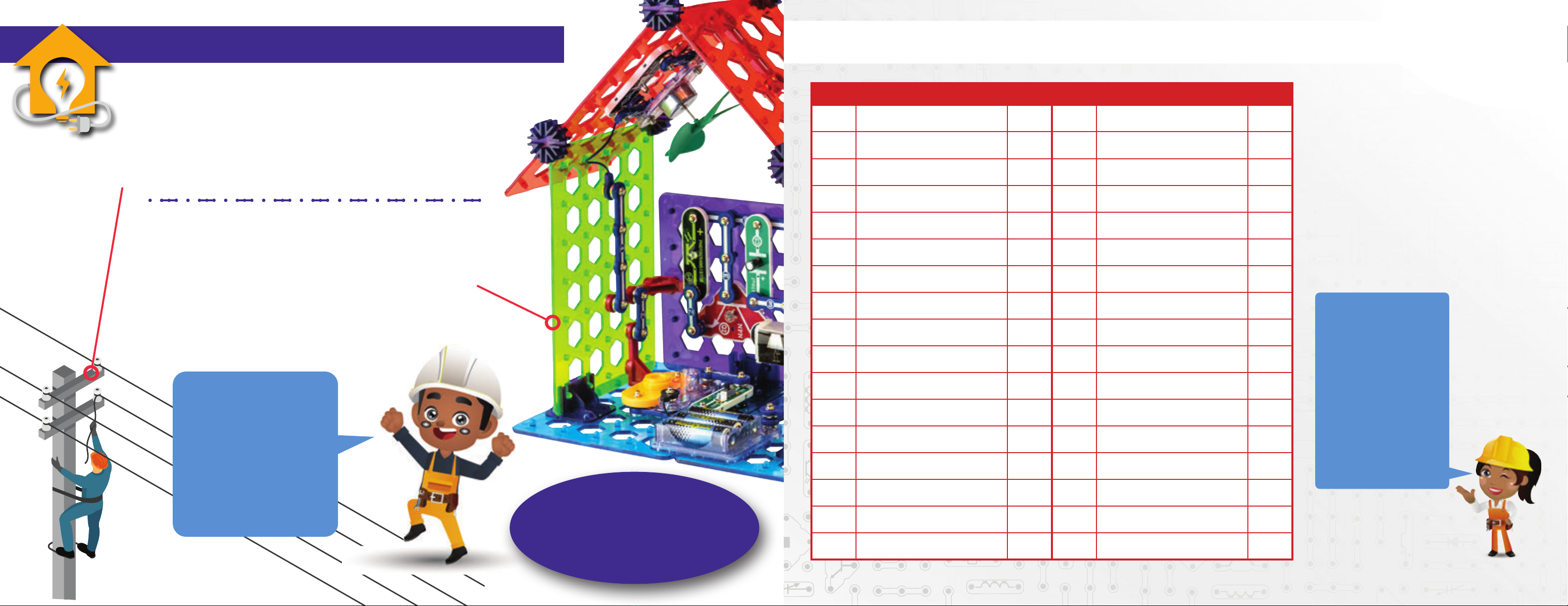
How do you turn on your light or your television or anything else that requires power in
your home1? You ip a switch, right? And if the switch doesn’t work, what do you do?
Anything that requires power (or charging) in your home must be ‘plugged in’ to the wiring
inside the walls of your house or your building. The wiring inside your house is connected to the
power cables on your street. And the power cables on your street are connected to the power lines
that travel through your community and, eventually, back to the power plant.
These electrons ow through metal
wires the same way water ows
through pipes.
You may have seen how water
wheels use owing water or a
waterfall to power machines,
right? Well, devices like motors,
speakers, and light bulbs use
owing electrons to do things
like move cars, play music,
and make light. The water that comes out of your
faucets has to come from somewhere. That water
is pumped through pipes from your city’s water
storage facilities or, if you live in the country, from
your well outside. In the same way, the electricity in
your house or building is pumped through wires or cables
from your city’s power stations. That electricity has to come
from somewhere too.
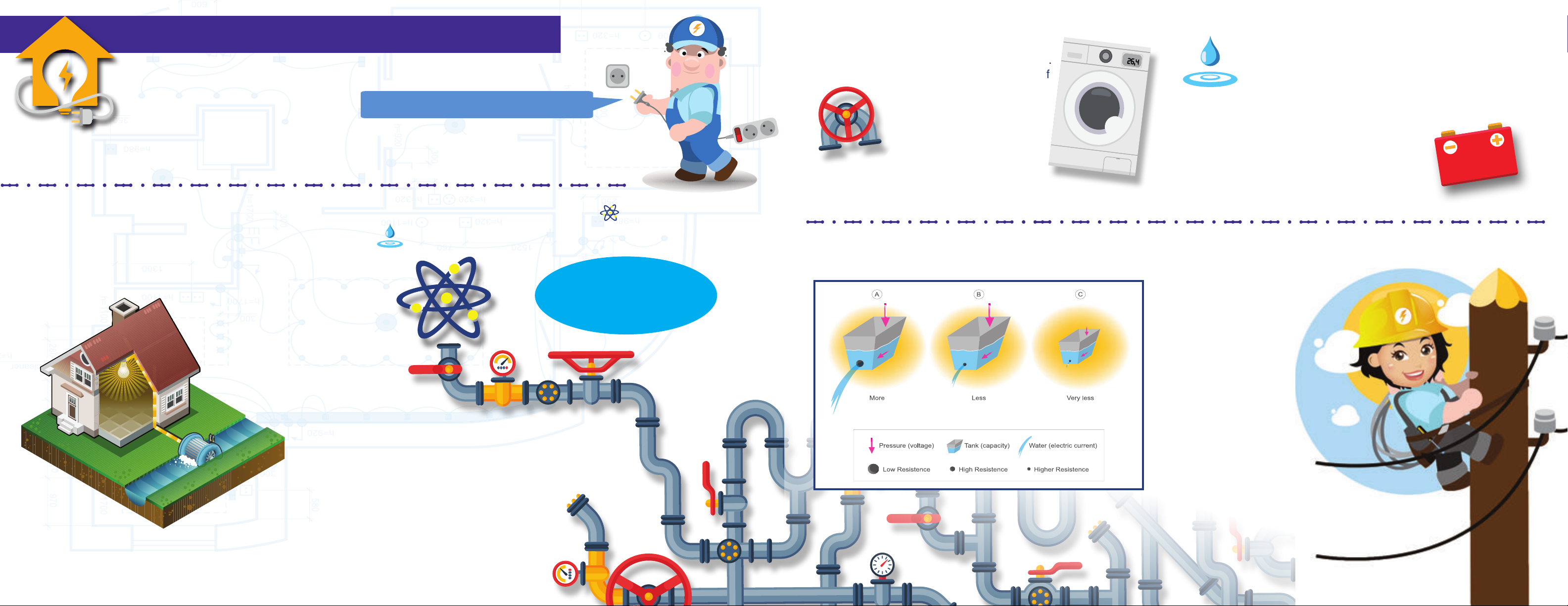
Valves and faucets control the ow of water
throughout your home and into appliances
like your washing machine and refrigerator.
Switches and transistors control the ow of
electricity throughout your home
and into appliances like lamps
and fans. Turning a switch
off blocks the passage
of electricity the way that
turning a faucet off blocks
the passage of water.
The amount of pressure (or push) a pump puts on the water inside a pipe is measured in PSI (pounds per square inch).
The amount of pressure a battery (or other power source) puts on the electrons inside a wire is measured
in V (volts) and is called the voltage.
The speed that water ows
in the ocean or through a
pipe is called its current.
Electrical current
(measured in amperes
(A) or milliamps
(mA, 1/1000 of an
ampere)) is the speed
that electricity ows
through a wire. In
either case, the faster
the speed, the higher
the current. Any electric
current measurements you
make with this set will be in
milliamps.
Like water, electricity must ow in one direction in order
to do its work. It has to get from the power station to
your house, and on to the next house and the buildings
thereafter. The power station only pumps electricity in
one direction, so you have no choice in the matter.
You just plug into a power outlet, and you’re ready to go. It’s
not so easy with portable power sources like
batteries. Fortunately, batteries have (+) and
(-) signs to show you which direction they pump
their electricity. This is why you have to put your
battery in ‘the right way’, taking care that the (+)
side of the battery is in the (+) side of the battery
holder, in order for it to work.
Nobody really knows what electricity is.
We just know that it is associated with the movement of subatomic charged particles called electrons .
Just as water is made up of bazillions of tiny water droplets , electricity is made up of bazillions of tiny electrons.
You check to see if it’s plugged in.
Your world
is powered
by electricity.
INTRODUCTION TO ELECTRICITY INTRODUCTION TO ELECTRICITYINTRODUCTION TO ELECTRICITY4
5 6
INTRODUCTION TO ELECTRICITY INTRODUCTION TO ELECTRICITY
Components can be arranged in series in any order and still have the same combined effect on the electricity owing
through them. Same thing goes for components arranged in parallel. In this way, we combine smaller ‘integrated’ circuits
to produce the large and complicated circuits that power our cell phones, our computers, and our entire world.
Example of a Parallel Circuit
The power provided by a battery
(or other power source) is the
amount of work that its stream of
electricity can do at any given moment.
A harder stream of water will get more dirt
off your car, right? This is because a hard stream
of water has more power than a weak stream. Batteries that
produce harder streams of electrons have more power too. And just
as the power of an ocean wave is a combination of its size and speed, the
power of an electrical source is a combination of its voltage and the current it can
provide. The mathematical relationship is Power = Voltage x Current,
and power is measured in W or watts.
In order to ow, electricity needs a complete circuit of conducting wire.
This means it must have a continuous wire pathway from
the (+) side of the battery (or power station) to the (-)
side of the battery (or power station). We can place
components (like a light bulb, motor, or appliance)
in the path of the electricity and they will slow the electricity
down, but they will not stop it. Only a break in the main
transmission line (called a circuit break) can do that.
The voltage of the power source is a constant value - it’s printed
on every battery. So if the resistance goes up, the current must go
down, and vice versa (if the resistance decreases, the current must
increase accordingly).
The resistance of an electrical component or circuit indicates
how much it resists the electrical pressure (voltage) by blocking
the ow of electrons. The larger the blockage in a clogged pipe,
the more slowly water ows through it, right? In the same way,
electricity ows more slowly through components with higher
resistances (measured in ohms,Ώ). Sometimes we place special
components called resistors in a wire pathway for the sole purpose of
slowing down the electrons owing through it.
As long as there are no breaks in its wire
path, electricity can take side tracks along its
main transmission line from the (-) to the (+)
side of its power source, providing electricity
to appliances, homes, and whole towns.
When components are placed along these
side tracks, we say they are in parallel to the
main transmission line.
Components that are placed directly along the main transmission line are said to be in series. In this
case, the electrons have only one pathway from the (-) to the (+) side of the power source.
When multiple components are placed in parallel, the electrons are given as many
paths to follow as there are parallel components.
More water ows more quickly through a partially blocked pipe than
a nearly clogged one, right? In the same way, more electrons ow more quickly
along the pathway with the least resistance. For components in parallel, the lowest
resistance dominates.
The current, voltage, and resistance of an electrical system are all related to one another through
this simple mathematical equation:
This equation is very important in electronics.
Voltage = Current x Resistance.
Example of a Series Circuit
Think about it this way: If there are three small blockages in one garden
hose, the amount of water that comes out will be determined by the worst
blockage, right? Same thing with electricity.
The ow of electrons through multiple components in series will slow down the
most when they travel through the component with the highest resistance.
For components in series, the largest resistance dominates.
7 8
ELECTRICITY IN OUR WORLD ELECTRICITY IN OUR WORLD
Large arrays
of solar cells produce electricity.
ELECTRICITY IN OUR WORLD
A small amount of the electricity we use comes from the chemical energy in batteries
(like the AA batteries in your B3 battery holder), but most of the electricity
used in our world is produced at enormous generators driven by
steam or water pressure, or (increasingly) by wind or solar.
Wires are used to efciently transport this energy to homes
and businesses where it is used. Once there, motors inside our appliances
(the ones that are plugged in and turned on) turn that electricity back into the
mechanical motion required to make these appliances work. The most important aspect of
electricity in our society - more important than the benets of the Internet - is that it allows
energy to be easily transported over distances.
Fossil fuels (coal/oil/natural gas)
or nuclear fuels are burned/consumed to
produce high-pressure steam that drives
electric generators. Dams create high water
pressure that drives electric generators.
Windmills use wind to drive electric generators.
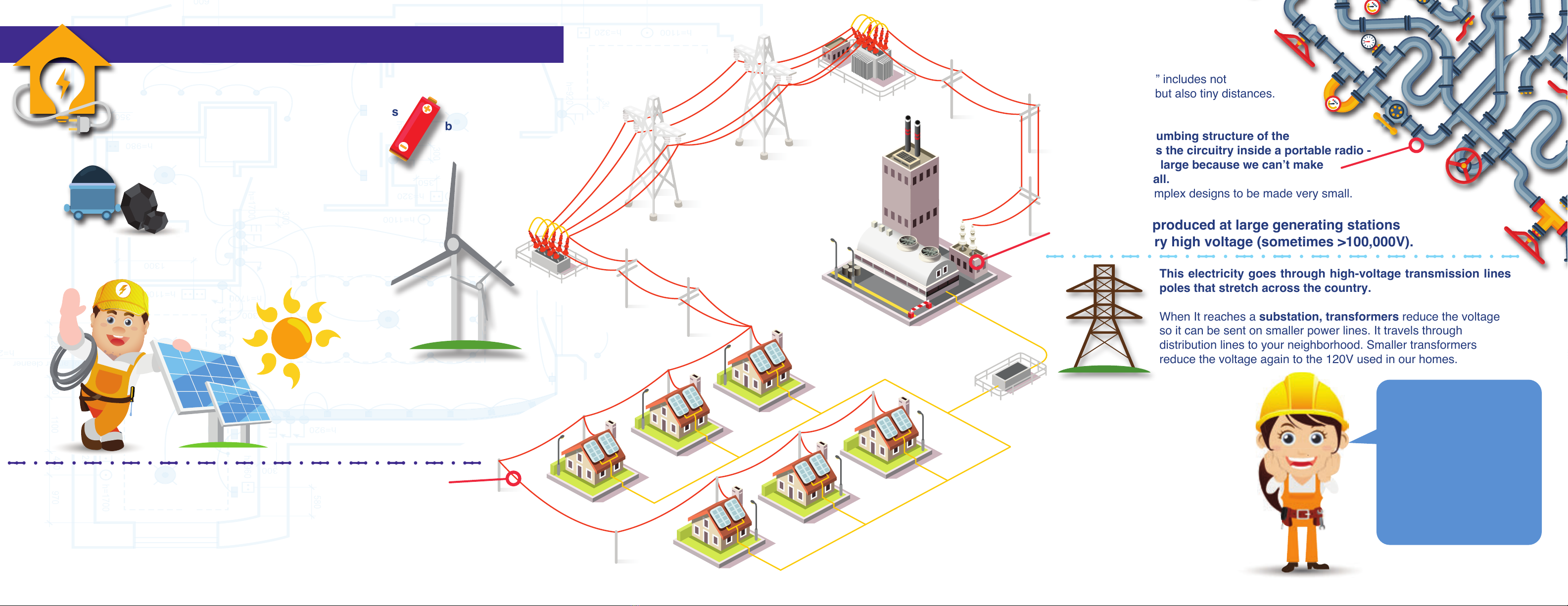
Note that “distances” includes not
just large distances but also tiny distances.
Try to imagine a plumbing structure of the
same complexity as the circuitry inside a portable radio -
it would have to be large because we can’t make
water pipes so small.
Electricity allows complex designs to be made very small.
Most electricity produced at large generating stations
comes out at very high voltage (sometimes >100,000V).
This electricity goes through high-voltage transmission lines
poles that stretch across the country.
When It reaches a substation, transformers reduce the voltage
so it can be sent on smaller power lines. It travels through
distribution lines to your neighborhood. Smaller transformers
reduce the voltage again to the 120V used in our homes.
Electricity is transported over long
distances at high voltage because this
reduces the amount lost in transmission,
compared to transporting it at lower
voltage.
Power = voltage x current,and the amount
of electricity lost in transmission is proportional
to current, so transformers change the ratio
of voltage to current to allow electricity to be
transported more effectively over long distances.
Projects 1-2 will show how
electricity can generate
motion in a motor, and
projects 5-6 will show how
motion in a motor can be
used to produce electricity.
This concept may not seem
important to you but it is
actually the foundation of
our present society’s power.
Transformer
Substation
9 10
ELECTRICITY IN OUR HOME ELECTRICITY IN OUR HOME
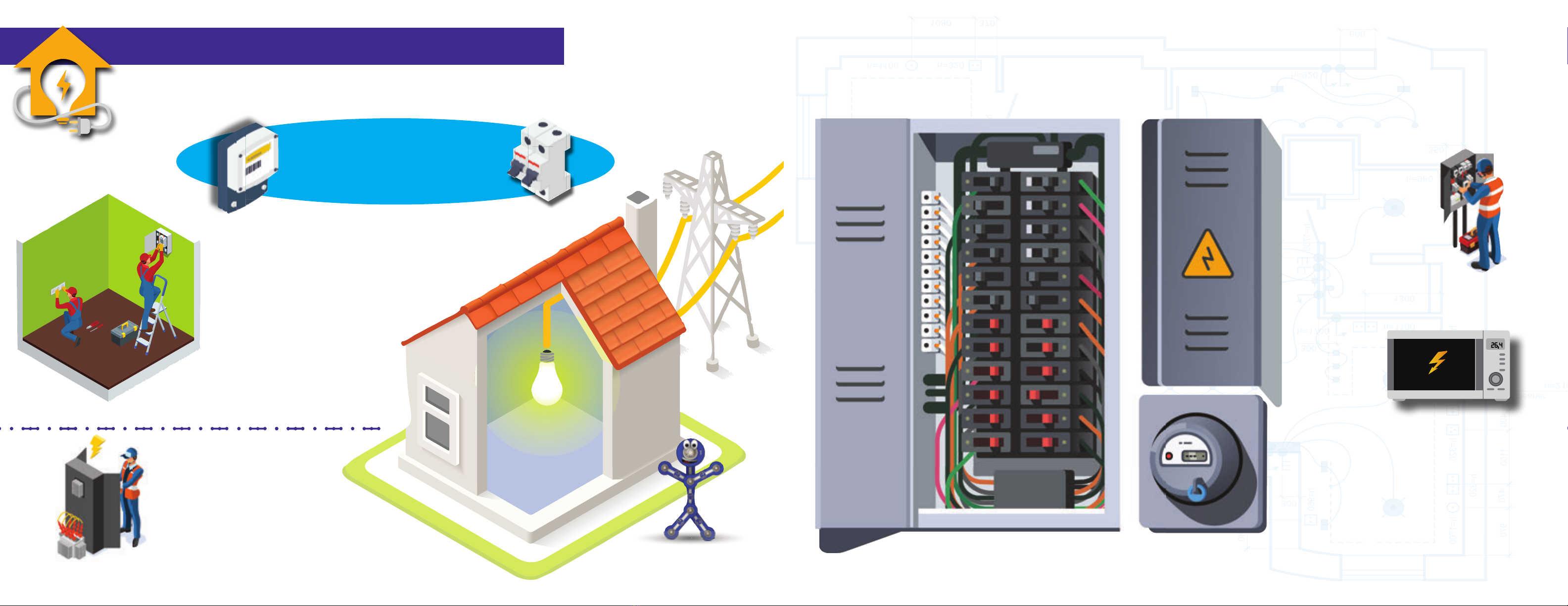
Before it goes into your house or building, the electricity produced at the power station goes through a meter
and is measured by your electric company to determine how much you are using (and how much it will cost you).
AS ELECTRICITY ENTERS YOUR HOME
Fuses are designed to shut down a circuit when the current
gets too high. This can happen when a person uses an
appliance the wrong way, or when the appliance is
designed badly or just malfunctions. When a high
current spike passes through a fuse, it causes
the fuse to break. With the fuse broken,
the metal pathway into your house
is also broken (disconnected),
so that electricity can no longer
ow. This shutdown prevents further
damage to the circuit and can prevent
explosions or res. Fuses are important for
safety and most electrical products have one.
Fuses in your home’s fuse box are designed to prevent a problem in
part of your house from starting a re or affecting the rest of your house.
But fuses are not designed to protect
you directly from getting hurt when you
use an electrical appliance in your home
because the normal operating power of
some appliances is already enough to be
dangerous to people.
If lightning hits a
transmission line or
electrical cable entering
your house, it can cause a
massive spike of electricity
to suddenly pass through the
cable and into your home.
So much electricity in such a short space
of time can overload your appliances,
burning out their
components
or electrical
connections,
which can
cause a re.
Fortunately, the wires enter your home
through a service panel, where fuses and
circuit breakers will block this high-powered
electricity from damaging your home and
your family.
(Learn more about lightning in Project 34)
The electricity then goes through a service
panel (usually in the basement or
garage), where fuses or circuit breakers
protect the wires inside your home from
being overloaded.
Some fuses need to be
replaced after they “blow”, but
others can be reset by ipping
a switch, and some
(like the one in your B3 battery holder)
can reset automatically.
1211 ELECTRICITY IN OUR HOME
PROJECT LISTINGS
Project Description Page Project Description Page
1Meet Your Parts 13-14 18 Electric Heater 35
2Wire Up! Lights Can Share The
Same Circuit 15 19 Water Completes Circuit 35
3 Dependent Lights 16 20 Automatic Light 36
4 Independent Lights 17 21 Tree Lighting 36
5 Windmill 17 22 Transistor Amplier 37
6 Mini-Windmill 18 23 Light & Sound 37
7 Overhead Lights 19-20 24 Audio Fan Speed Adjuster 38
8 Electric Home 21-24 25 Distance Loss Simulator 38
9 Home Security 25-26 26 Light-Controlled Light 39
10 Block the Sound 27 27 Photo Control 39
11 Materials Tester 28 28 Infrared-Controlled Light 40
12 Dim Color Light 28 29 IR Control 40
13 Mini Battery 29 30 2-Story House 41-42
14 Storing Electricity 30 31 3-Wall House 43-44
15 Fader 32 32 High Ceiling House 45-46
16 Timed Wall of Fun 32 33 2-Story Building 47-48
17 Festive House 33-34 34 Static Electricity 49-50
When lightning (or ice or wind) causes a tree to fall
and break a power line, a gap is created in the line that cuts off
electricity to every building along its route. If it is a main transmission
line, entire towns and cities can lose power until the line is repaired.
When this happens, it’s no use plugging your appliances in and turning them
on, the electricity is ‘out’. This is when batteries come in handy; and your phone,
your car, your video-game controller wouldn’t be the same without them.
AS ELECTRICITY ENTERS YOUR HOME
After successfully passing through the fuses or circuit breakers in
your service panel, the electricity travels through wires inside your walls
to outlets and switches all over your house. The electrical wiring in your
house is hidden by plaster and wooden walls, ceilings, and oors and
requires a lot of work to install and access when repairs are needed.
Use your electrical appliances according to their instructions in
order to ensure the electricity in your house works the way it’s intended.
It’s your home and
your power, you
should know how it
works to keep your
gadgets going and
to stay safe! Thank you
to children’s author Melissa Rooney, PhD,
for her assistance in writing the Introduction
and other sections of this manual.
You can nd out more about Melissa at
www.melissarooneywriting.com.
Projects 1-2 demonstrate your
parts in simple circuits.
Projects 3-4 demonstrate
simple circuit arrangements.
Projects 5-6 demonstrate
using a motor as a generator.
Project 7 is a simple 3D circuit
construction.
Project 8 demonstrates and
explains what electricity does
in a home.
Projects 9-29 are basic circuits
and applications.
Projects 30-33 are large 3D
home circuits.
Project 34 demonstrates static
electricity.

13 14
+
50mA
Comparing Electric
Flow to Water Flow: Pump
Resistor
Valve
WHAT IS REALLY HAPPENING HERE ?
Project 1 | MEET YOUR PARTS The circuits in this
book often do not use
a resistor or other
component to slow down
the electrical current
passing through the
LED. Normally this would
damage an LED, because
LEDs can only handle
very low currents (much
smaller than the current
provided by your battery).
But your Boffin LEDs
have resistors built into
them, and these internal
resistors protect the
LEDs by slowing down
the current. Be careful if
you use electrical sets
with unprotected LEDs,
as you will need to use
external resistors to
prevent them from
burning out.
Boffin uses electronic blocks that snap onto a clear
plastic base grid to build different circuits. These blocks
have different colors and numbers so you can easily
identify them. This set contains five different color base
grids, you may use any one to build the circuit.
Build the circuit shown on the left by placing all the parts with a black 1
next to them on the base grid rst. Then, assemble parts marked with a 2.
Install three (3) “AA” batteries (not included) into the battery holder (B3) if
you have not done so already. Set the meter (M6) to the 50mA setting.
Turn on the slide switch (S1). The white LED (D6) lights and the meter
measures the current.
Placement Level Numbers
Part B: Replace the white LED with the color LED (D8, “+”
on top) and enjoy the light show as the meter measures the
current. For best effects, dim the room lights.
Part F: Replace the motor with the phototransistor (Q4, “+”
on top) and vary the amount of light shining on it. The current
measured on the meter varies from near zero when you cover
the phototransistor to high when you shine a ashlight directly
on it.
Part G: Replace the phototransistor with the 5.1kΩ resistor
(R3) and see the current on the meter. The current will be
very low, but you can change the meter to the 0.5mA setting
to conrm that some current is owing.
Part D: Replace the lamp with the melody IC (U32, “+” on top)
and listen to the sound as the meter measures the current.
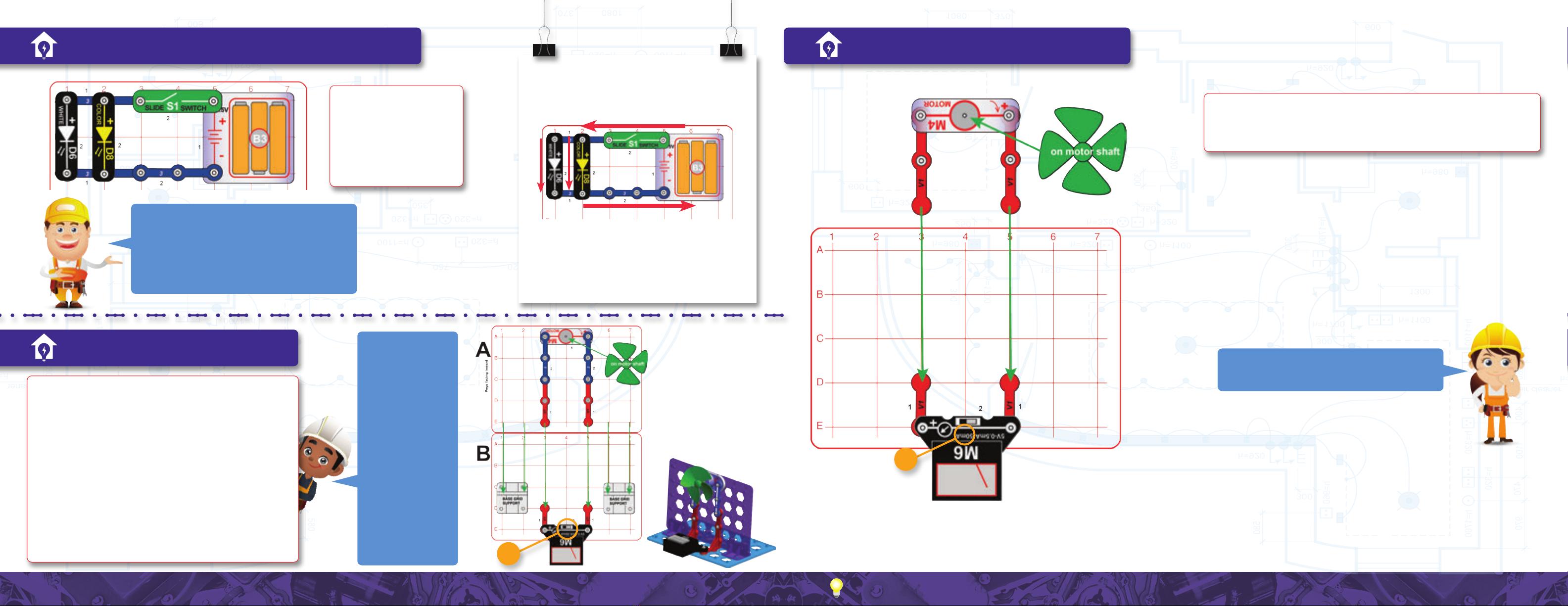
Part E: Replace the melody IC with the motor (M4) and green
fan and see the fan spin as the meter measures the current.
Reverse the orientation of the motor to make the fan spin in
the opposite direction (this changes whether the fan blows air
up or down).
1. The batteries (B3) convert chemical energy into
electrical energy and “push” it through the circuit,
just like the electricity from your power company.
A battery pushes electricity through a circuit like
a pump (or gravity in the case of a water tower)
pushes water through pipes.
2. The snap wires (the blue pieces) carry the
electricity around the circuit, just like wires
carry electricity around your home. Wires carry
electricity like pipes carry water.
3. The meter (M6) measures how much electricity
ows in a circuit, like a water meter measures how
fast water ows in a pipe.
4. The white LED (D6) converts electrical energy into
light, it is similar to a lamp in your home except
smaller. LEDs are increasingly being used for
home lighting because they are more efcient
than other types of bulbs. An LED uses the energy
carried by electricity, resisting its ow like a pile of
rocks resists the ow of water in a pipe.
==
=
=
=
=
5. The slide switch (S1) controls
the electricity by turning it on
or off, just like a light switch
on the wall of your home. A
switch controls electricity like
a faucet controls water.
6. The base grid is a platform
for mounting the circuit, just
like how wires are mounted
in the walls of your home to
control the lights.
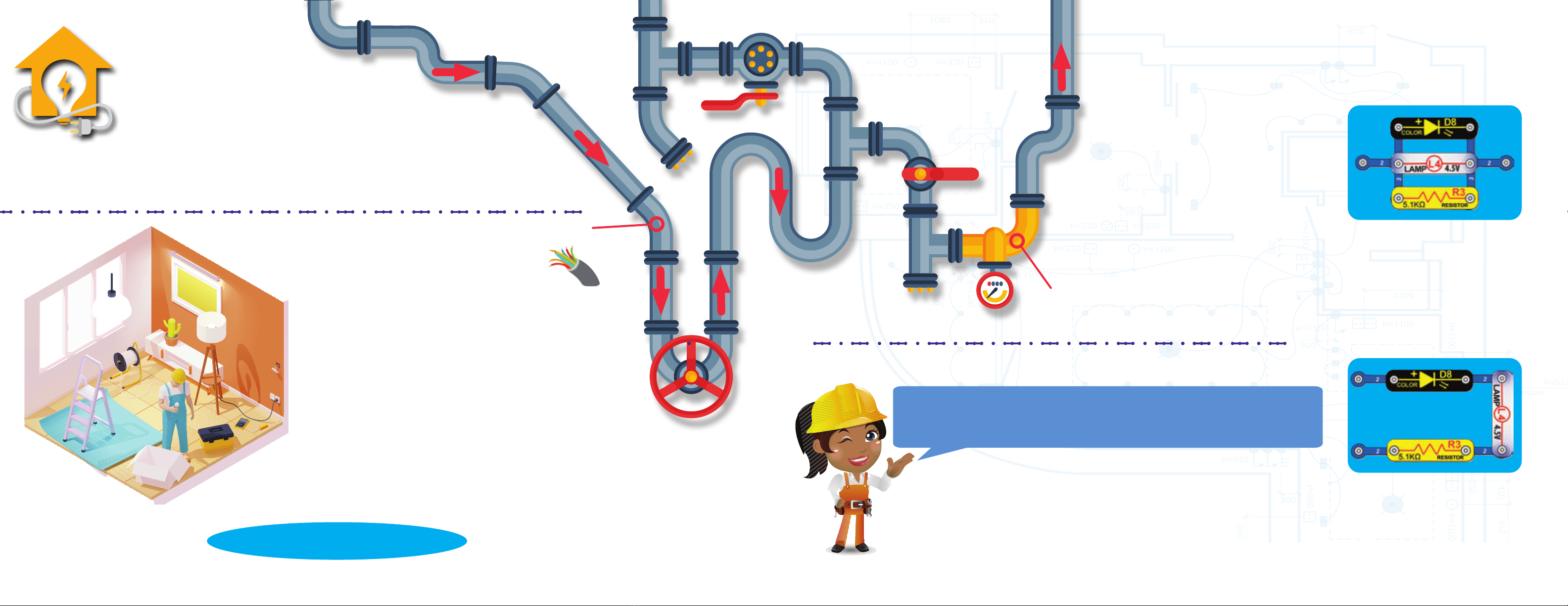
Part C: Replace the color LED with the lamp (L4). The current
measured on the meter will be very high and off the scale
(you are measuring a 200mA lamp with a 50mA meter).
Incandescent light bulbs are much less energy efcient than
LEDs. Do not leave the circuit for two minutes because the
lamp will be hot.
To learn more go to pages 55-57.
LEDs are light emitting diodes, which convert electrical
energy into light. The color of light from an LED depends on
the characteristics of the material used in it. The color LED
actually contains separate red, green, and blue lights, with a
micro-circuit controlling them.
The lamp (L4) converts electricity into light. It is an
incandescent light bulb, just like other incandescent bulbs
in homes except smaller. In an incandescent bulb electricity
heats up a high-resistance wire until it glows, producing
light. Incandescent light bulbs are very inefcient, converting
less than 5% of the electricity used into light, with the
rest becoming heat. LEDs are much more efcient than
incandescent light bulbs, and are increasingly being used for
home lighting and ashlights.
The phototransistor is a material whose electrical resistance
varies depending on the amount of light shining on it.
A resistor “resists” or slows down the ow of electricity.
Resistors are used to limit or control electricity in a circuit.
The melody IC makes an electrical pattern from tunes
recorded in its memory. A speaker inside it then converts the
electrical pattern into sound by making mechanical vibrations.
These vibrations create variations in air pressure which travel
across the room. You “hear” when your ears feel these air
pressure variations.
The motor uses magnetism to convert electricity
into mechanical motion (see page 57 [About Your
Parts] for more explanation).
LED bulbs are much more energy efcient than incandescent light bulbs, using only 20% as much electricity to produce the same light. Turn off the lights when not in use.

15 16
Build the circuit shown. Set the meter (M6)
to the 5V setting. If desired, place the ber
optic festive tree in its mounting base and
on the color LED (D8). Turn on the slide
switch (S1) and enjoy the show.
The meter measures the voltage from the
batteries - this may be 4.5V if your batteries
are new, but will likely be less because the
circuit components are a heavy load on the
batteries. Try removing the lamp, motor,
melody IC, and LEDs, one at a time and
see how the measured voltage changes.
Do not leave the circuit for two minutes
because the lamp will be hot.
This is a single snap,
placed beneath other
parts as a spacer
Placement Level Numbers
The battery voltage (electrical
pressure) may drop as the current
increases, because the batteries may
not be able to supply all the current
the circuit needs. This eect is more
noticeable when the batteries are
weaker. The lamp needs much more
current than the other components,
so it has the greatest eect on the
battery voltage.
This circuit has both LEDs connected in SERIES. Series
circuits are simple to connect, and allow one component
to easily control another (here the white LED blinking is
controlled by the color LED’s blinking). The LEDs may
be dim because the battery voltage may not be high
enough to make both bright. If one LED breaks, then
the circuit is broken and neither will work.
The slide switch (S1) is also connected in series with
the LEDs, so it can turn them on and o.
A “brownout” occurs when power
plants cannot supply enough current
to a city during high demand,
and must reduce the voltage they
supply. This sometimes occurs on
hot days in summer when everyone
is using their air conditioners.
Project 2 | WIRE UP! LIGHTS CAN SHARE THE SAME CIRCUIT Project 3 | DEPENDENT LIGHTS
The two LEDs are connected in a series, and
all the electric current from the batteries ows
through each component in the circuit. The LEDs
are dim because the voltage from the batteries
(B3) is divided between them.
Connecting parts in series is one way of arranging
them in a circuit. The advantage of it is that wiring
them together is simple. The disadvantage is that
if one LED breaks, all will be off.
Build the circuit and turn
on the slide switch (S1).
The white and color
LEDs (D6 & D8) should be
blinking but may be dim.
If neither lights at all then
replace your batteries.
Note: base
grid colors are
interchangeable,
so use any color
you like.
17 18
Project 4 | INDEPENDENT LIGHTS Project 6 | MINI-WINDMILL
Project 5 | WINDMILL
50mA
50mA
Build the circuit and turn
on the slide switch (S1).
The white and color
LEDs (D6 & D8) are
bright now and only the
color LED is blinking.
Assembly:
1. Place base grid supports on base grid B.
2. Place parts on grid A, and install into base grid
supports on grid B.
3. Install remaining parts on grid B.
Set the meter to the 50mA scale and blow on the fan to
simulate a strong wind. You can also set the meter to
the 5V scale to measure the voltage produced.
Replace the meter with the color LED (“+” on left). If
you blow hard enough then the color LED (D8) will light.
Change the preceding circuit into this one. Now blow on the fan to
simulate wind. If you blow hard enough, the color LED (D8) lights up.
Is it easier to light the LED in this circuit or the previous circuit?
In this circuit the batteries produce an electric
current, which ows through the switch, then
divides between the 2 LEDs, then re-combines
and ows back into the batteries.
The two LEDs are connected in parallel with
one another. They are bright because each LED
gets the full battery voltage. Most of the lights in
your house are connected in parallel; so if one
bulb burns out then the others are not affected.
Compare this circuit to the preceding circuit. This
circuit has both LEDs connected in PARALLEL.
Parallel circuits make components independent of
each other but require more complex wiring (notice
how this circuit requires more parts than the preceding
circuit). Both LEDs are bright because each gets the
full battery voltage, but they will drain the batteries
faster. If one LED breaks then the other will still work.
This circuit improves the air ow by removing the base
grid from behind the fan, but it is not as physically
stable and comes apart more easily.
Here the clear motor
(M4) is a generator
that uses the
physical motion of
the windmill to pump
electricity through the
circuit. The motors in
commercial windmills
are much more
ecient, meaning
they generate less
heat and waste less
electricity. Windmills
also use fan blade
shapes and materials
that lower friction
(friction is how hard
the wind has to push
on the blades to
make them move),
so they can produce
electricity even in
light winds.
• If you want to save energy, set your thermostat so your home is a little cooler in the winter and a little warmer in the summer. Every extra degree of heating or cooling
reduces your energy cost signicantly. You can use a programmed timer to automatically reduce heating or cooling when you know you will be away from home or asleep.

19 20
Project 7 | OVERHEAD LIGHTS
Think of this circuit as a room
with an overhead light. Electricity
ows from the batteries on the
oor to the white LED on the
ceiling, down to the slide switch
on the other wall, and then back
to the batteries. The batteries
represent the power supplied by
your local electric company. The
white LED is a ceiling light. The
slide switch is the switch on your
wall that turns the ceiling light on
or o. And the blue snap wires
are the wires in the walls of your
house. The colored base grids are
just the structure of your house.
Assembly (adult supervision recommended):
1. Place base grid supports on base grids A & B.
2. Place parts on base grids C, & D, and install into base grid supports
on grids A & B. The pegs should be facing inward. Base grid colors
are interchangeable, so you any color you like at any location.
4. Place the remaining parts on grids A, B, & E.
Turn on the slide switch (S1) to light the white LED (D6).
Part B: Carefully replace the white
LED (D6) with the color LED (D8),
or carefully add the color LED next
to the white LED as shown here.
3. Mount grid E on top of grids C & D using 4 stabilizers, attaching the
2 vertical snap wires (V1) as you do it.
Note: Base grid colors
are interchangeable,
so use any color you
like at any location.
Go to www.boffin.cz for an interactive 3D picture to help with
constructing this circuit.

21 22
These red pieces are
the same vertical snap
wire (V1), mounted so
it stands up.
The grids t into the
supports easier if
the column marking
(1-7) is on this side.
The grids t into the
supports easier if
the column marking
(1-7) is on this side.
This is a single snap,
placed beneath other
parts as a spacer
50mA
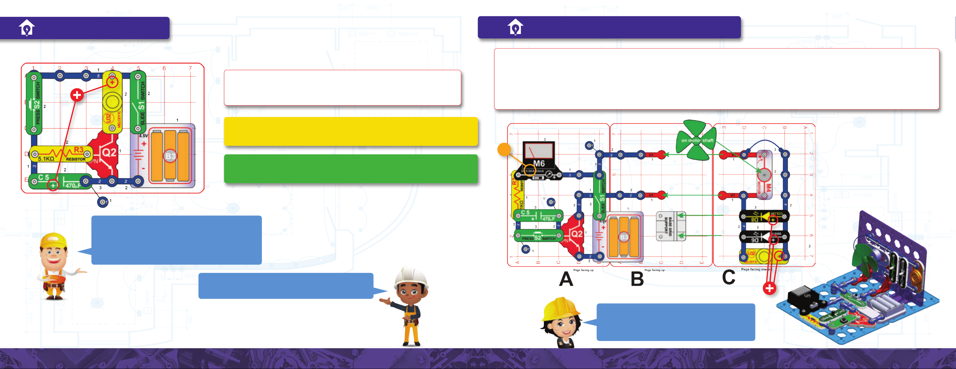
Project 8 | ELECTRIC HOME Assembly (adult supervision recommended):
1. Place base grid supports on base grids A & B.
2. Place parts (except the blue jumper wires) on base grids C & D,
and install into base grid supports on grids A & B. The pegs should be
facing inward on grid C and outward on grid D. Base grid colors are
interchangeable, so you can use any color you like at any location.
4. Place the remaining parts on grids A, B, & E, including the two blue
jumper wires
This circuit does not have an on-off switch, so connect one of the
blue jumper wires last, and disconnect it when you are done using
this circuit. Set the meter (M6) to the 50mA setting. Turn on the slide
switch (S1) or push the press switch (S2) to make things happen, and
watch the current on the meter. The lamp (L4) will not light.
The light covers and slides may be placed on the LEDs (D6 and D8)
or lamp (L4) as decoration. Fold the slides as indicated and slide them
into the slots on the cover, as shown.
You can replace either LED (D6 or D8) or the melody IC (U32) with
fan for a
the motor (M4) and fan. The motor represents a ceiling fan,
furnace or air conditioner, or other appliance.
3. Mount grid E on top of grids C & D using 4 stabilizers, attaching the
2 vertical snap wires (V1) as you do it.
The light covers and slides may be placed on the LEDs (D6 and
D8) or lamp (L4) as decoration. Fold the slides as indicated and
slide them into the slots on the cover, as shown.
Running full loads in your dishwasher, clothes washer, or clothes dryer uses a lot less energy than two half loads.
Go to www.boffin.cz for an interactive 3D picture to help with
constructing this circuit.
23 24
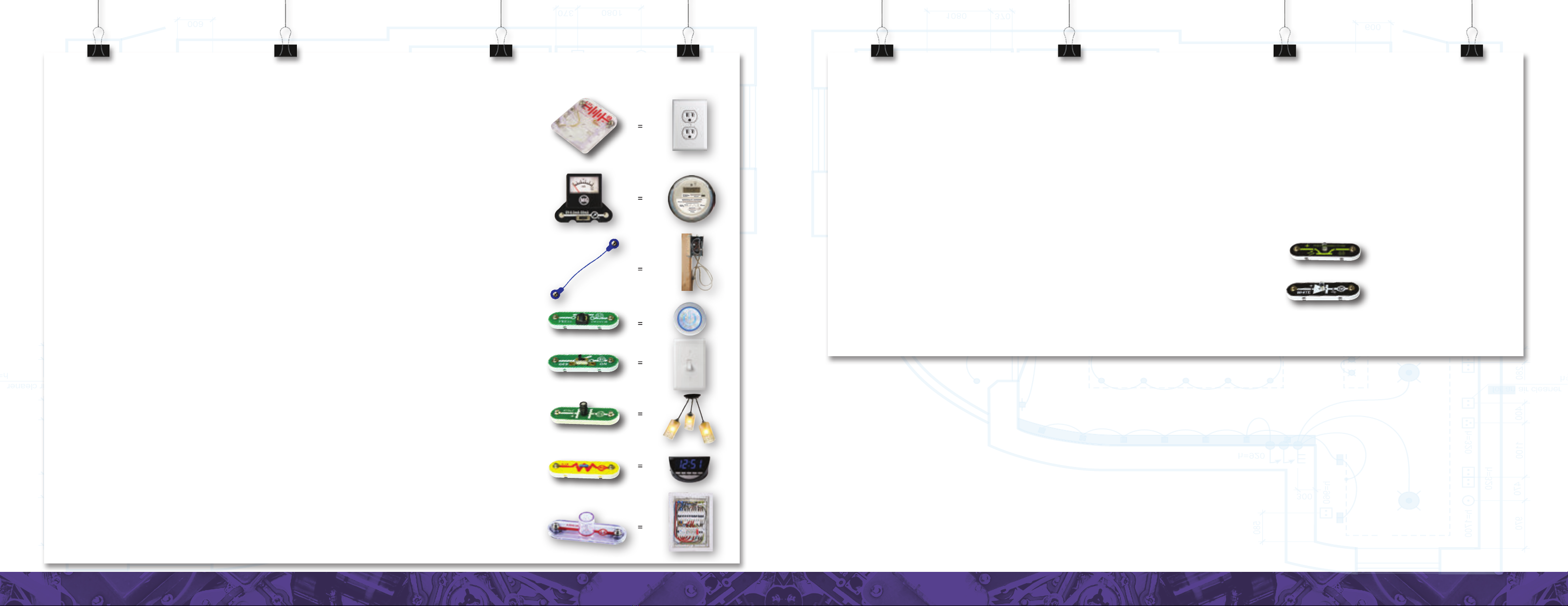
This Circuit Demonstrates How Electricity Is Used In Your Home:
The battery holder (B3) represents the electricity supplied to your home. Usually the electricity is
generated by a power station, but it could also come from a gasoline-powered backup generator, from
solar panels on your roof, from wind turbines, or from larger batteries.
The meter (M6) is the meter that measures how much electricity you’re using and reports it to your local
electric company. This meter is usually located on the outside of your house or somewhere nearby.
Your electric company uses this measurement to determine how much electricity you have to pay for.
Electricity is measured in kilowatt hours (kWh), which is the amount of electricity needed to power a
1000W light bulb for 1 hour. The present cost of 1 kWh of electricity in the United States is around ten
cents ($0.10).
The blue snap wires, jumper wires, and vertical snap wires (V1) represent the wires in your walls,
ceiling, and oor, by which electricity travels throughout your home to where it is needed.
The press switch (S2) turns on (or off) the color LED (D8, which represents your television or computer
screen) and the melody IC (U32, which represents your stereo or sound device).
The slide switch (S1) controls the white LED (D6) the same way a switch on the wall controls a ceiling
light.
The 470µF capacitor (C5) keeps the white LED glowing for a moment after you turn off switch S1, giving
you a little light to walk out of the room by. Try removing C5 and see how much faster the light turns off.
The 5.1kΩresistor (R3) represents various devices that are always on and using small amounts of
electricity, like your refrigerator, hot water heater, computer, television, and Wi. Change your M6 meter
to the 0.5-mA setting and see how much current ows to R3 when the S1 and S2 switches are off.
The lamp (L4) represents a fuse and will only light if there is a problem in your circuit. Normally L4
will be off.
What is a short circuit? You can connect an extra jumper wire across the 5.1kΩ resistor to simulate the short circuit problems that often
happen in homes. A short circuit occurs when the resistance in an electrical pathway is suddenly and drastically reduced, so that the electricity
suddenly ows very quickly. If you connect an extra jumper wire across the 5.1kΩ resistor you bypass the resistor, so the current doesn’t have to
go through it at all (it goes through the jumper wire instead). Because there is nothing blocking its way, the current ows much more quickly through
the jumper wire, causing meter M6 to go off the scale and the lamp to light up. Although the meter continues to show a current overload (off the scale),
the resistance of the bright lamp slows down the current enough to prevent damage to the wires and batteries down the line (representing the electric
company’s infrastructure). Note that when the lamp is on, turning the S1 and S2 switches on does not illuminate the LEDs or make the melody sound.
This is because the fuse has shut down the electricity owing through your home as a result of the short circuit you caused across the 5.1kΩ resistor.
When you remove the jumper wire from across the resistor, the lamp turns off, the meter returns to normal, and the S1 and S2 switches work again. (A
similar fuse is also built into your B3 battery holder; but it resets automatically, so you don’t even notice it’s working.)
The phototransistor (Q4) is used here to help hold grids A & B together. It is not electrically
connected to the other components.
Replacing either LED (D6 or D8) or the melody IC (U32) with the motor (M4) and fan creates a
ceiling fan or the fan in a furnace, air conditioner, or other appliance.

25 26
Other side
view
Project 9 | HOME SECURITY Assembly (adult supervision recommended):
1. Place base grid supports on base grid A & B.
2. Place parts (except for the jumper wires) on base grids C & D, and
install into base grid supports on grids A & B. The pegs should be
facing inward.
Place a small object inside this house. If an intruder reaches in to grab it, the alarm will sound and the
color LED will ash to scare the intruder away.
This circuit works like the security systems in a lot of people’s homes, which are activated when a beam of
light is broken or when motion or a loud sound (like a window breaking) is detected. Some home security
systems are linked to a monitoring company, which contacts the police when the alarm is activated.
Turn on the slide switch (S1); the white LED (D6) should be on, but
there should not be any sound. Now place your hand between the
white LED and the phototransistor (Q4); an alarm sounds and the
color LED (D8) turns on.
Easier Rooess Version: Skip assembly steps 4 and 5, and the jumper
wires from step 2. Grids E and F, and all parts on them are not used. The
circuit works the same way except that the color LED (D8) is not included.
3. Place remaining parts
on grids A & B.
4. Place parts (except
jumper wires) on grid E.
How it works: Light from the white LED
(D6) shines on the phototransistor (Q4),
which keeps the photoresistor’s resistance
low (so it blocks electrical ow very little).
When the white LED is shining, the current
that ows through resistor R3 must also
ow through Q4. If a burglar blocks the
light from the white LED, Q4’s resistance
increases, blocking the ow of current
through Q4. The current owing through
R3 begins to ow into transistor Q2, which
turns it on so that electricity now ows
through the melody IC (U32) and color LED
(D8) that are serving as your home alarm.
Sealing cracks, gaps, leaks, and adding insulation can signicantly reduce home heating and cooling costs.

27 28
IF NEEDED
Project 10 | BLOCK THE SOUND
Assembly (adult supervision recommended):
1. Place base grid supports on base grids A&B.
2. Place parts on grids C&D and install into base grid supports on grids A&B.
3. Install remaining parts on grids A&B.
Turn on the slide switch (S1); the white LED (D6) and melody IC (U32) are on.
Place your hand to block the light between the white LED and phototransistor
(Q4); the sound stops. Hint: The light in your room may be keeping the sound
on, to check for this, try pointing the phototransistor away from your room light.
This circuit is the opposite of the
Security House project (rooess
version). The positions of resistor
(R3) and phototransistor (Q4) have
been switched, reversing how the
melody IC (U32) is activated. Now
the “alarm” is always on unless
you block the light to turn it o.
Some materials, like copper, gold, and platinum metals, have very
low resistance to electricity, meaning electrons travel through
them very easily. This is why the lamp glows brightly and the meter
measures a large current. Because we can conduct electricity (or
make it ow) through these materials, we call them conductors.
Other materials, like paper, air, and plastic, have very high
resistances to electricity, meaning they nearly block the ow of
electrons completely. We call these kinds of materials insulators.
If you incorporate these insulating materials into the circuitry,
they cause the lamp to turn o and the meter to read a current of 0
even at its lowest setting (0.5 mA).
The best conductor known to humans is silver, but it would be very
expensive to build circuits out of silver. Copper is the second-best
conductor and, because it is much cheaper, it is used in almost all
electrical wiring.
Project 11 | MATERIALS TESTER
Build the circuit and set the meter (M6) to the 50mA setting. Turn on the slide switch (S1)
and touch (or connect) various materials between the loose ends of the red & black jumper
wires. See which materials are good at transporting electricity by watching the meter current
and lamp (L4) brightness. Try string, the electrodes, a shirt, plastic, paper, two of your ngers,
wood, or anything in your home.
If the meter reads zero, switch it to the 0.5mA setting to see if there is just a very small current.
To help protect the meter, always switch back to the 50mA scale before testing a new circuit.
Which materials gave the highest reading on the meter, and which gave the lowest?
Build the circuit as shown and turn on the slide switch (S1); the color LED (D8) will be dim. Push the press
switch (S2) to make the LED much brighter.
Next, replace the color LED (D8) with the white LED (D6) and compare the results.
Project 12 | DIM COLOR LIGHT
You can calculate the resistance of the materials you tested using
Ohm’s law: Resistance = Voltage / Current. From the information on your batteries, you know that
the Voltage is around 4.5V, and you can measure the Current using the meter.
WHAT IS RESISTANCE: If you rub your palms together very quickly, they will begin to feel warm.
The friction between your hands converts the physical motion of your body into heat. Resistance is
the friction between an electric current and the material it ows through; and, like friction, resistance
creates heat as well. We use electrical components called resistors to increase this electrical friction
(resistance) to control how electricity ows through circuits. In this circuit, the resistor (R3) decreases
the brightness of the LED, makes it dimmer but which also makes the batteries last longer.

29 30
50mA
A
B
5V
Project 13 | MINI BATTERY
Electricity ow
Build the circuit as shown and set the meter to the 50mA setting. Turn on the slide
switch (S1) until the meter current drops to zero (indicating the 470µF capacitor
(C5) is fully charged), then turn the switch off. Push the press switch (S2) to
discharge the capacitor through the white LED (D6), lighting it. Turn S1 on and off
and then push S2, several times.
Now turn S1 on and off, but then remove C5 from the circuit and place it across
points A & B (“+” to A) and the color LED (D8) lights. Return C5 to the original
circuit and repeat.
Pushing S2 while S1 is on connects the batteries directly to the white LED, and
makes the effects of the capacitor difcult to see.
Build the circuit as shown and set the meter (M6) to the 5V
setting. Turn on the slide switch (S1) and watch as the voltage
slowly rises to 3V or more. Next push the press switch (S2) for
a moment; the fan wiggles and the voltage drops to 0. Repeat
this several times.
Part B: Replace the slide switch (S1) with the 5.1kΩ resistor (R3) and set the
meter to the 0.5mA setting. Now the capacitor charges up very slowly, because
the resistor limits its charging current.
Watch the current measured by the meter.
Turning on S1 allows electricity to ow from the
batteries into capacitor C5, causing the current to
increase; but the ow of electricity stops when C5
is fully charged (that is, when all the electrons that
can crowd into the capacitor do so). In this way,
charging a capacitor is a lot like lling a water
tank – you can only push as many electrons/
water droplets into them as they can hold.
When S1 is off and you press S2, the electricity
that is stored in C5 ows through S2 and lights
the white LED. The LED stays lit until C5 is
discharged, meaning all the electrons that
crowded into the capacitor have dissipated
or moved away. Dissipating a fully charged
capacitor is like opening the valve at the bottom
of a full water tank – once the path is cleared,
both water and electrons will ow freely.
Capacitors like C5 store electricity
like tiny rechargeable batteries.
Although they can’t store as much
electricity as batteries, capacitors
can store and release electricity
much faster than batteries. And,
like a battery, a capacitor can
store electricity for a long time.
To demonstrate this, once C5 is
charged, remove it from the main
circuit and place it across the mini
circuit containing D8.
Capacitors and rechargeable
batteries are used in many devices
in your home to store information,
like the date or time, when the
devices are turned o or when the
power goes out in your home.
How it works: the 5.1kΩresistor (R3) slows the
ow of electricity from the batteries, causing
the capacitor (C5) to charge up slowly and
the voltage reading on the meter to increase.
Pushing S2 discharges the capacitor, so that
electricity ows through the motor. But the
capacitor can only store enough energy to
make the fan wiggle for a moment. Once the
capacitor’s charge has dissipated (meaning all
the water has drained out of the tank), no more
current will ow, so the fan does not move.
Project 14 | STORING ELECTRICITY
For outdoor lighting, you can use a photocell or timer, so the lights are off when there is daylight, or use “motion sensitive” lights instead of continuous lighting.
31 32
0.5mA
Project 15 | FADER Project 16 | TIMED WALL OF FUN
Build the circuit as shown, turn on the slide switch (S1), and then push the press
switch (S2) to hear a melody. After you release the press switch the sound slowly
fades out. Push the press switch to resume the sound.
Part B: Replace the melody IC (U32) with the motor (M4) and fan. The fan spins for
a time after the press switch is released.
Part C: Replace the motor and fan with the white LED (D6). The LED slowly dims
after you release the press switch.
Pressing S2 instantly charges up the 470µF capacitor (C5) and makes
a control current ow into the NPN transistor (Q2), which turns on the
melody IC. When S2 is released, the electricity stored in C5 slowly
drains into Q2 through the 5.1kΩresistor (R3), keeping the transistor
and melody IC on for a short time until the capacitor has discharged.
The white LED stays on longer than the melody IC or motor, because
the white LED can operate at a lower current than the others.
Capacitors are used in fading circuits like this in your home, like when
the light slowly fades as you leave the room or you hear a short stretch
of music after you have turned o the radio.
The lights, fan, and sound are on while capacitor C5 is charging,
then stop as the capacitor gets fully charged. Pressing S2
instantly discharges the capacitor and resumes the fun. The
circuit would run longer if you used a higher value resistor or
capacitor, because then the charging would take longer.
Assembly:
1. Place the base grid support on base grid B.
2. Place parts on grids C and install into base grid supports on grid B.
3. Install remaining parts on grids A&B.
Set the meter (M6) to the 0.5mA scale, push the press switch (S2), and then
turn on the slide switch (S1). The motor (M4) spins the fan, the LEDs (D6
& D8) light, the melody IC (U32) plays a tune, and the meter measures the
current charging the 470µF capacitor through the 5.1kΩ resistor. The meter
shows the current decreasing and soon everything stops. Push the press
switch to re-start the circuit.
33 34
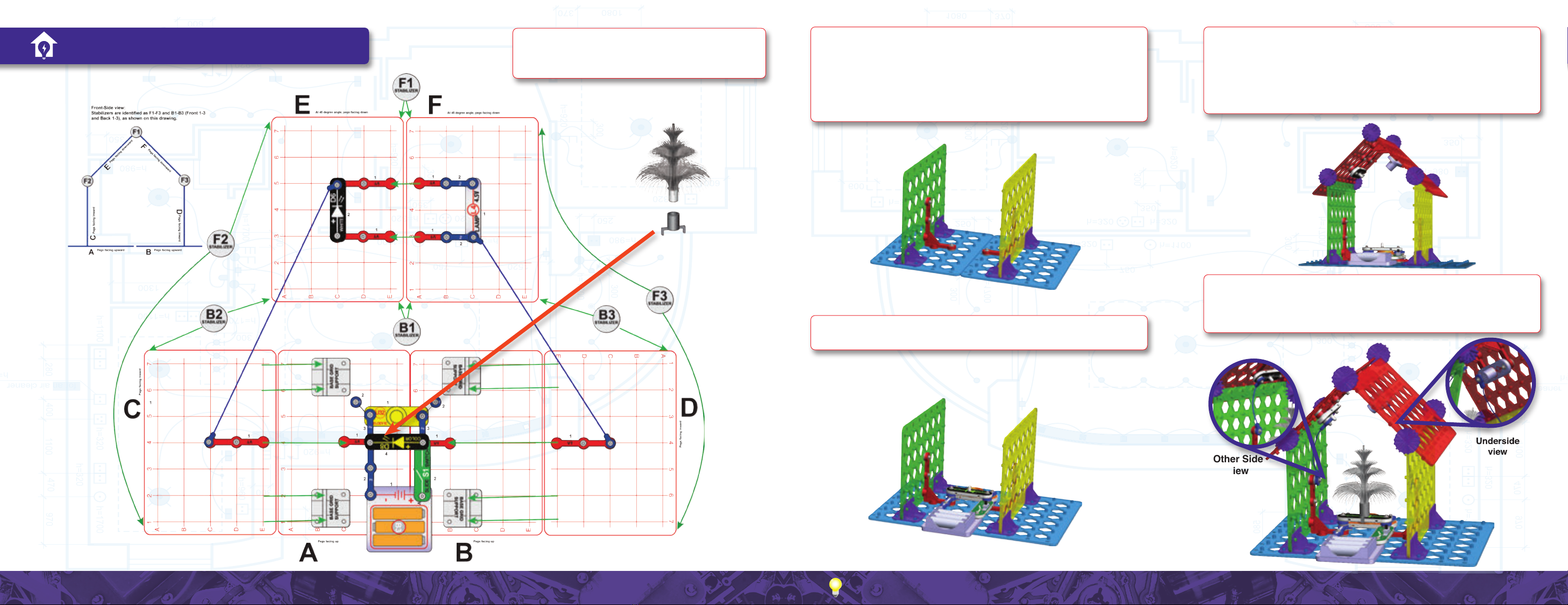
Project 17 | FESTIVE HOUSE
Other Side
view
Assembly (adult supervision recommended):
1. Place base grid supports on base grids A & B.
2. Place parts (except for the blue jumper wires) on base grids C & D,
and install into base grid supports on grids A & B. The pegs should be
facing inward.
Do not leave the circuit for two minutes
because the lamp will be hot.
4. Mount grids E & F, at the angles shown and with pegs facing down,
on top of grids C & D using 6 stabilizers, and attaching 2 vertical
snap wires (V1) as you do it. Adjust the positions of the stabilizers as
needed.
5. Add the remaining parts on grids E & F.
6. Add the 2 blue jumper wires, and place the ber optic festive tree in
its holder and on the color LED (D8). Turn on the slide switch (S1) to
light the LEDs (D6 & D8) and lamp (L4).
3. Place remaining parts on grid A & B.
Turning off your computer, monitor, printer and fax machine when you are not using them saves electricity. They use electricity in stand-by or low-power mode.

35 36
CAUTION: very warm lamp enclosure.
Project 18 | ELECTRIC HEATER
Turn on the slide switch (S1), cover the
holes in the top of the lamp (L4) with
your nger, and wait. After a minute
or so you should feel the lamp heating
up. Do not leave the circuit for two
minutes because the lamp will be hot.
Build the circuit and turn on the slide switch (S1). The white LED (D6) will be on
unless there is bright light on the phototransistor (Q4), so vary the amount of light
shining on the phototransistor.
The melody IC (U32) will make little or no sound (it is used here to help control the
phototransistor current).
Use two vertical snap wires (V1) and mount the white LED (D6) on them so it will shine towards the festive
ber tree, mounted on the color LED (D8). Turn on the slide switch (S1) and place the circuit in a dimly lit room.
Part B: Instead of placing the red & black jumper wires in
water, touch the metal part of each with your ngers, using
your body to complete the circuit. Wet your ngers to get
better electrical contact. The white LED (D6) should be on,
but brightness may vary.
There is no danger in touching the circuits you build with
Boffin because of the low-voltage batteries they use (4.5V).
But the electricity from your electric company is a much
higher voltage (120V), and it can seriously injure and even
kill you if it enters your body. This is why it is important that
you never touch a wire without disconnecting it from the
electricity (by turning it off and unplugging it) or without
placing proper insulation (materials that electrons cannot
travel through) between you and the wire (which is why
most of the wiring inside appliances has a colorful plastic
coating).
Distilled (or ltered) water has almost no impurities (or things other than
water molecules) in it. Because of this, distilled water has a very high electrical
resistance, meaning that current doesn’t ow through it easily.
The water that comes out of your tap has chlorine, uoride and other chemicals
to make it safe for you to drink. Because of these impurities, tap water has a
low electrical resistance, meaning that current ows through it rather easily.
Adding salt (sodium chloride) to the water decreases its resistance even more,
because this adds sodium and chloride ions (or moveable charges) to the mix.
This is why it is incredibly important that you don’t enter a swimming pool
when there’s a chance of lightning. If lightning occurs anywhere near the pool,
the high-energy electrons will follow the path of least resistance straight into
the water and, because your body is mostly water, into you.
Incandescent light bulbs like L4
contain a special thin wire that gets
so hot when electricity ows through
it that it glows. Only about 5% of the
electricity used in incandescent light
bulbs is used to make light; the rest
becomes heat, which is why you can
feel the L4 lamp heat up when you
cover its venting holes. Electric space
heaters convert electricity to heat in a
similar way to warm up a room.
This circuit automatically
turns on the light when the
room starts getting dark.
Build the circuit as shown,
leaving the ends of the red &
black jumper wires unconnected
for now. Turn on the slide switch
(S1); the white LED (D6) should
be off.
Place the loose ends of the red
& black jumper wires into a cup
of water (but not distilled water),
without them touching each
other. The white LED should be
on now, because water conducts
electricity, completing this circuit.
Try dissolving some salt in the
water or using different liquids,
and see how the LED brightness
changes. You can also replace
the white LED with the color
LED (D8).
Don’t drink any liquids
used here.
Project 19 | WATER COMPLETES CIRCUIT
Project 20 | AUTOMATIC LIGHT
Project 21 | TREE LIGHTING
Because tap water is conductive (low resistance),
dropping a live wire (a wire that is plugged into your
house’s electricity) into your bath connects every wet part
of your body to the 120V electricity flowing through the
wiring in your house.

37 38
A
B
C
D
5V
Project 22 | TRANSISTOR AMPLIFIER Project 24 | AUDIO FAN SPEED ADJUSTER
Project 23 | LIGHT & SOUND
Project 25 | DISTANCE LOSS SIMULATOR
Turn on the slide switch (S1). The color LED
(D8) is dim but the white LED (D6) is bright.
Turn on the slide switch (S1). The fan should spin and there should be sound
from the melody IC (U32). If the fan does not spin then push the press switch
(S2) to get the fan started.
This circuit is intended to simulate electrical transmission loss
over long distances. Turn on the slide switch (S1). The color
LED (D8) is bright but the white LED (D6) is not at full brightness.
Set the meter (M6) to the 5V setting and place it across points
A & B to measure the voltage across the color LED, and then
across points C & D to measure the voltage across the white LED.
Turn on the slide switch (S1) to get a blinking light with funky
sounds. You can change the sound by removing the lamp (L4).
Part B: Remove either LED (D6 or D8) and
see what happens to the other one.
Part C: Swap the locations of the white
LED (D6) and the color LED (D8).
Part D: In the original circuit, replace the color
LED with the press switch (S2). Notice that
the white LED is only on when S2 is pressed.
The NPN transistor (Q2) is a current amplier,
meaning it takes a small current and makes it
larger. When a small current ows into Q2 through
the left branch (through D8), a larger current will
ow into Q2 through the right branch (with D6).
Green arrows show the current ow. This is why
the LED on the right side will be brighter than the
LED on the left side. In fact, the current in the right
branch can be as much as100 times larger than the
current in the left branch.
The left branch controls the right branch, so
removing D8 turns o D6, but removing D6 does
not aect D8.
A small electric current may be owing through
the color LED even when it appears to be o.
This small current, when it pass through the NPN
transistor (Q2) and gets amplied, can be enough
to keep the white LED on.
This circuit uses the blinking pattern of the color LED (D8) to
control the current owing through the lamp (L4) and melody
IC (U32), making them go on and o. The NPN transistor (Q2)
allows D8 to control the other electrical components. The
melody IC does not start up instantly, so the blinking pattern of
the color LED produces unusual sound eects in the melody IC.
The speed of the fan varies depending on the
current owing into the melody IC, and the melody
IC current depends on the sound it is making.
The color LED is only separated from the batteries by the slide switch (S1), so
it gets the full battery voltage (pressure) when the switch is on. The white LED
is separated from the batteries by the 5.1kΩ resistor R3 (which represents the
loss of electrical energy when it is transmitted over long distances); this slows
down the current so that the white LED has a noticeably lower voltage across it.
Leaving your charger cord plugged in when there is no phone/device charging wastes electricity.
Table of contents
Popular Toy manuals by other brands

FoamFly
FoamFly Insta-Plane B-25 instruction manual

RC Aerodyne
RC Aerodyne 500 scale fuselage AS350 instruction manual

Fisher-Price
Fisher-Price GeoTrax M4098 instruction sheet

Enabling Devices
Enabling Devices 209 user guide

LGB
LGB 20310 instruction manual

J. Perkins
J. Perkins Twister Hawk Assembly & flight training guide


