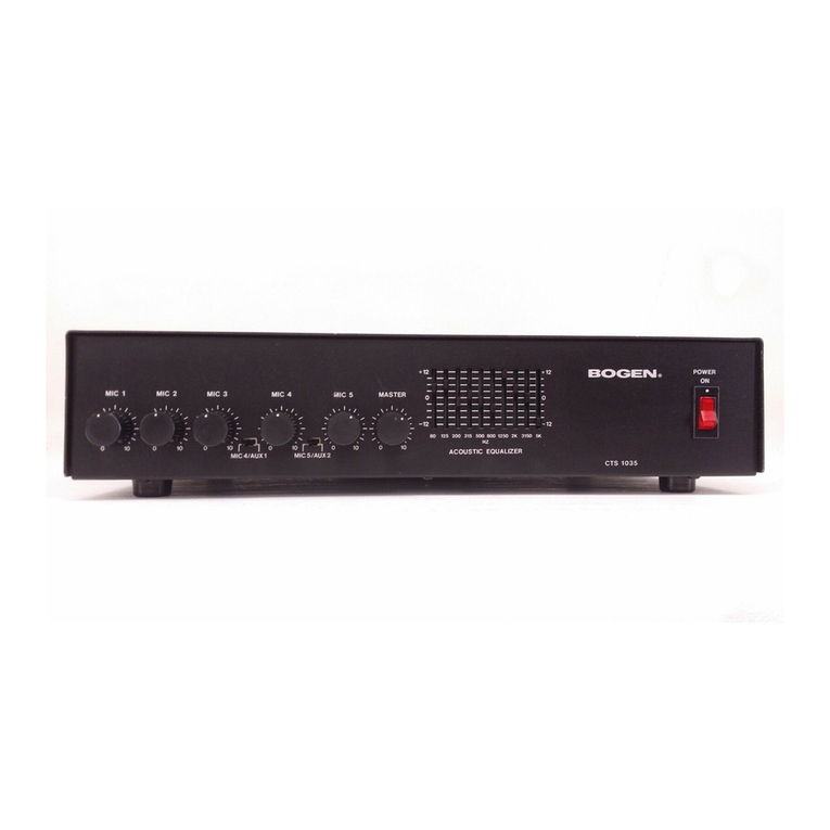
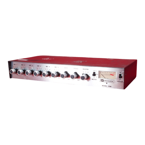
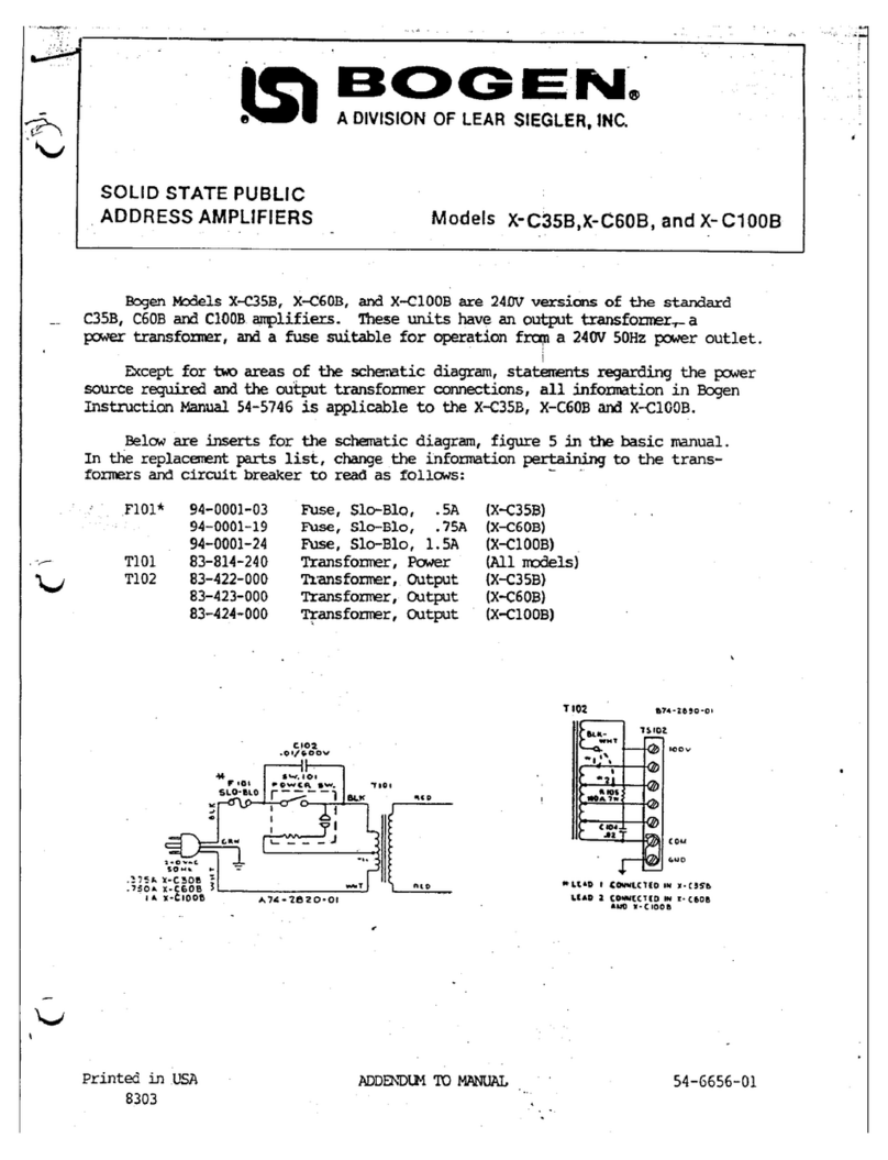
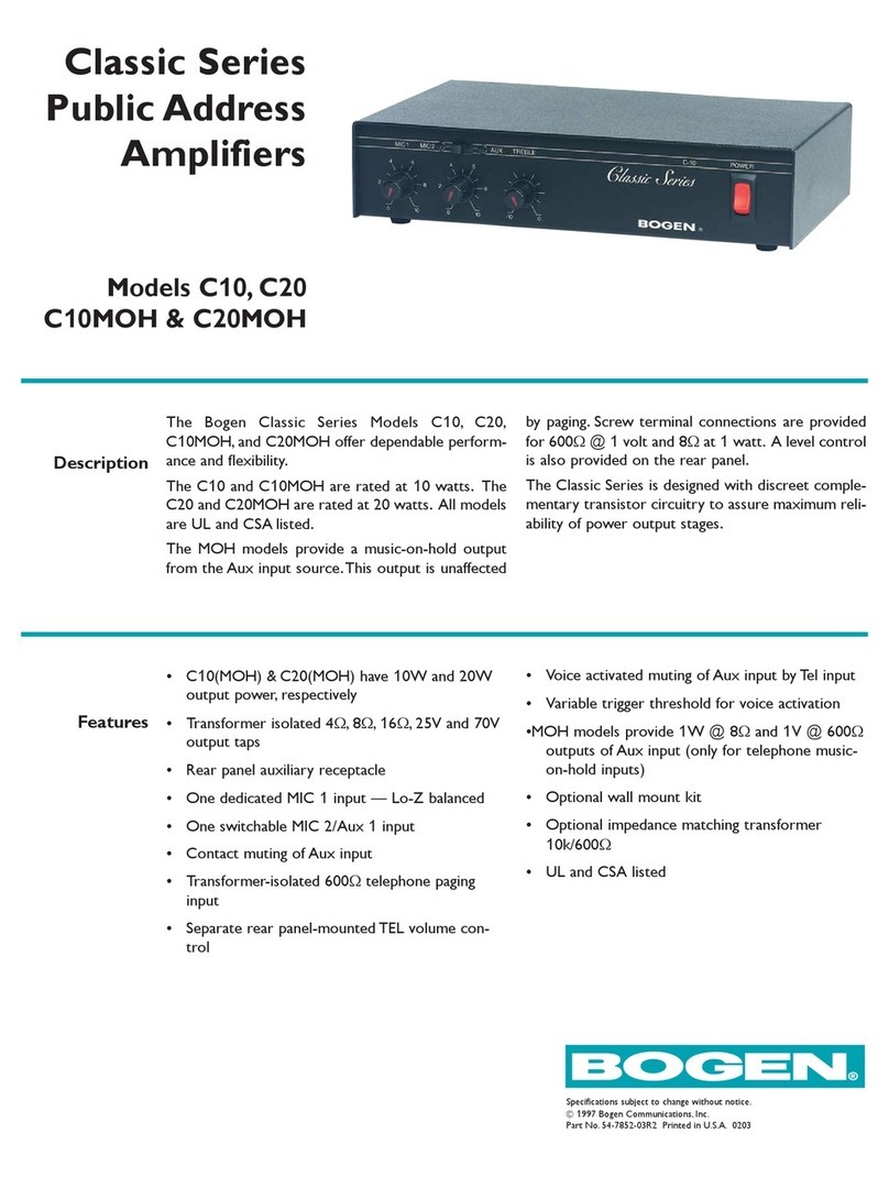
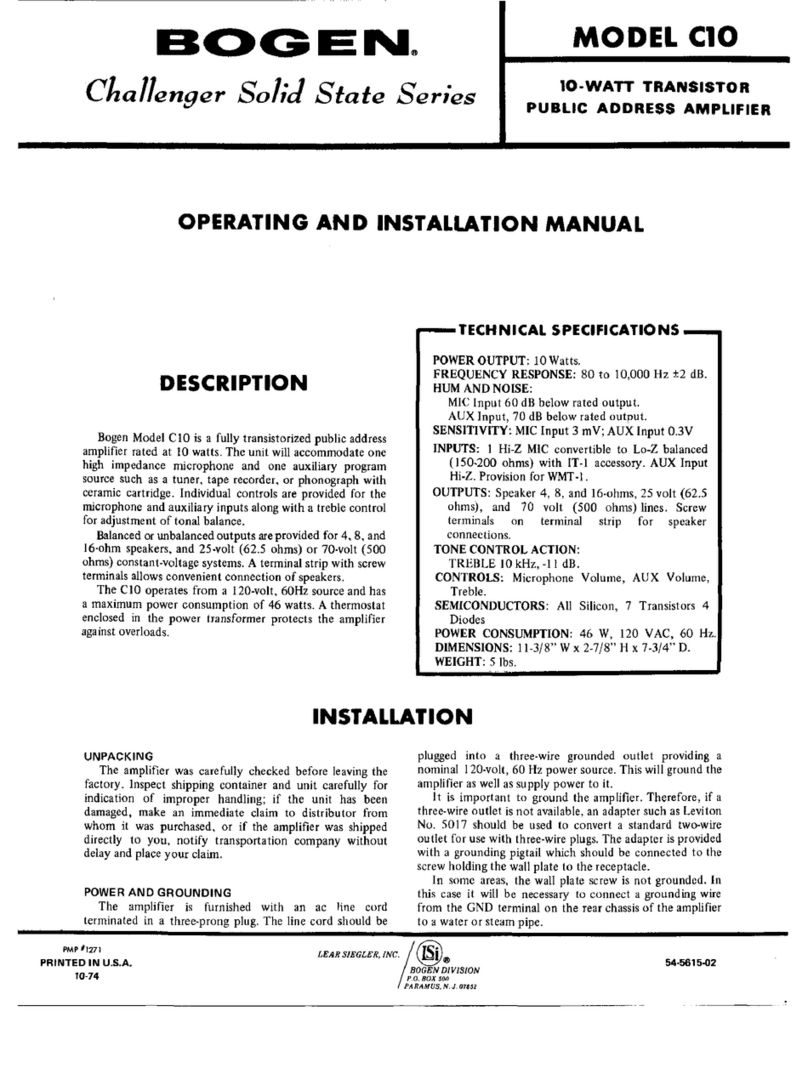
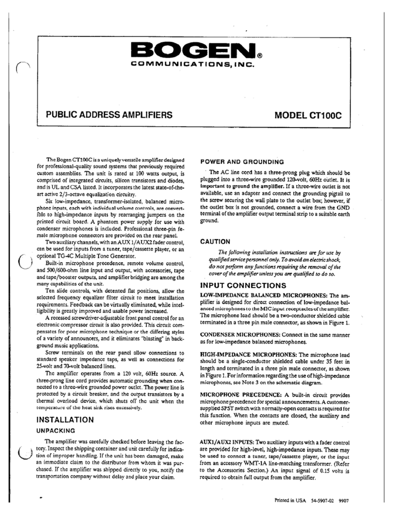
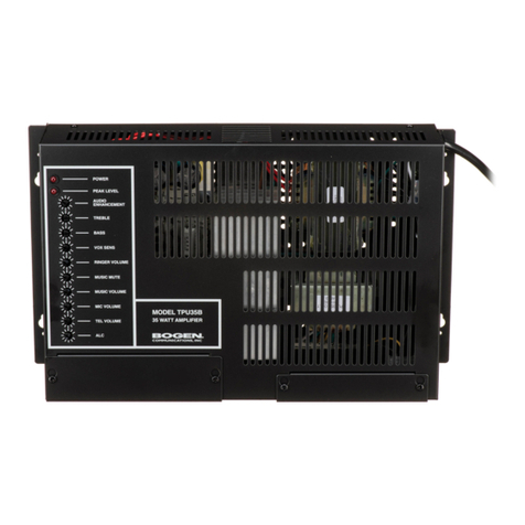
Bogen Classic C35 User manual

/
'
•*''
>{
•.,1
jCj-;
•-.fr";
Classic
Series
Public
Address
Amplifiers
Models
C35,
C60j
and
C100
Sn
^
II
ji
0\
54-5979-08
Printed
In
Korea
9i03

TECHNICAL
SPECIFICATIONS
Power
Output:
Ouq)ut
Connections:
Screw-type
te
rminals;
C55—35WRMS
TAPE/BOOSTER
jack;
provisions
for
WMT-IA
C60—60WRMS
Controls:
MIC
1,
MIC
2/AUX
1
{selector-switch),
AUX
croo—100WRMS
2,
BASS,
TREBLE.
TEL
Distortion:
Less
than
^%,
70H2
to
I6KH2
@
-2dB.
Tone
Control
Action:
4-Ohm
Direct
Ouput—
0.5%,
2OI2
to
2CMCH2
at
7reb/e—±11dB
at
10kH2
rated
power
Bass—±11dB
at100H2
Frequency
Response:
Power
Requirements:
120VAC,
6OH2
7OH2
to
IOKH2,
±2dB
@
-2dB
C35—
85
watts
4-011111
Direct
Ouput—
2OH2
to
2OKH2
±1dB
C60—148
watts
Hum
and
Noise:
C/CO—220
WQtts
MiC
Input
55dB
below
rated
output
Overload
Protection:
Electronic
overload
protection
AUX
input
70dB
below
rated
output
Thermal
Protection:
Thermistor
attached
to
heat
sink
TEL
70dB
below
rated
povwr
Electrical
Protection:
Circuit
breaker
Input
Sensitivity:
Dimensions:
MiC
Lo-Z
Balanced—
600pV
C35—
14-1/2"W
X
S-SM-H
x
10-5/8"D
AUX—BbmM
(37
X
9.6
X
27cm)
TEL
—75mV
060,
C100—
14-1/2'Wx
S-SMTH
x
11
"D
Outputs:
(37
X
9.6
X
28cm)
8,16
ohms,
25V,
and
70V
balanced;
Shipping
Weight:
4
ohms
unbalanced.
C35—15
lbs.
Input
Connections:
Tvto
MIC
Lo-Z
te
rminals,
two
AUX
.C60—18
lbs.
Hi-Z
jades,
Tel
C/00—
20
lbs.
.I";
Hie
Bogen
Classic
Series
models
CSS,
C60,andC100
are
the
latest
evolutioii
of
die
long
line
of
pc^ular
C
Series
of
amplifiers.fiom
Bogen
Communications.
Th^
surpass
pre
vious
models
inbodi
peifomm^
and
flexibUi^,
and
include
new
features
and
sle^
1990*s
sQ^lingi
Ihe
models
are
rated
at
35
watts,
60
watts,
and
100
watts.
Each
Classic
Series
amplifier
offers
a
choice
of
inputs:
2
Lo-Z
balanced
microphone
inputs
and
1
Aux
input,
or
1
Lo-Z
microphone
and
2
Aux
inputs.
A
TEL
input
is
also
provided
to
permit
paging
from
a
telephone.
A
built-in
microphone
precedence
circuit
lets
you
mute
the
Aux
2
channel
with
die
use
of
a
customer-supplied
switch.
This
lets
you
mute
back
ground
music
from
a
tuner,
CD
or
cassette
player
when
you
mate
a
public
address
aimouncement.
Independent
volume
controls
are
provided
for
each
input.
Treble
and
bass
controls
offer
tonal
balance.
Output
screw
terminal
connections
are
provided
for
8
and
16
ohm
balanced
and
4-ohm
unbalanced
systems,
and
also
for
25-volt
and
70-volt
constant-voltage
speaker
systems.
Output
jacks
let
you
patch
into
a
tape
recorder
or
an
additional
(booster)
amplifier.
An
accessory
transformer,
Bogen
Model
WMT-IA,
can
be
installed
to
allow
output-matching
to
a
telephone
line.
The
amplifiers
operate
fixim
a
120VAC,
60Hz
source
and
are
equipped
with
thermal
breaker,
electronic
overload
and
electrical
circuit
breaker
protection.
INSTALLATION
UNPACKING
The
amplifier
was
carefiilfy
checked
before
leaving
the
factory.
Inspect
the
shipping
container
and
unit
carefully
for
indication
of
improper
handling.
If
the
unit
has
been
dam
aged,
make
an
immediate
claim
to
the
distributor
from
whom
it
was
purchased.
If
the
an^lifier
was
shaped
directly
to
you,
notify
the
transportation
comparq'
without
delay
and
place
your
claim.
POWER
AND
GROUNDING
The
AC
line
cord
has
a
three-prong
plug
which
must
be
plugged
into
a
three-wire
grounded
120-volt,
60Hz
outlet.
It
is
important
to
ground
the
amplifier
properly.
INPUT
CONNECTIONS
MICROPHONES:
Two
low-impedance
balanced
micro
phones
may
be
connected
simultaneously
to
the
screw
termi
nals
on
the
rear
panel
of
the
amplifier.

MICROPHONE
PRECEDENCE:
A
buUt-in
circuit
pro
vides
microphone
precedence
over
the
AUX
2
channel.
For
this
fi
inction,
a
customer-supplied
normally-open
SPST
switch
must
be
connected
to
the
AUX
2
MUTE
terminals.
When
the
contacts
are
closed,
the
microphone
will
have
precedence
over
the
AUX
2
input.
AUXILIARY:
The
AUX
inputs
may
be
used
for
ai^
signal
source
having
a
high-level
output,
including
sudi
Bogen
equipment
as
the
TF-50A
and
TP-IOOA
AM/FM
"nmcrs,
CR-100
Cassette
Player/Tuner,
and
TG-4C
Multiple
Tone
Generator.
TEL:
Connect
the
telephone
line
to
the
TEL
tenninals.
OUTPUT
CONNECTIONS
SPEAKERS:
The
amplifier
m^
be
used
with
most
conven
tional
speaker
systems.
Coimect
onespeakerlead
tothe
screw
terminal
which
cone^nds
to
die
impedance
of
the
speaker
system
and
the
other
lead
to
the
COM
terminal.
If
the
line
is
Welded,
connect
die
shield
to
GND.
For
balanced
ouqiut
lines,
lemoye
the
link
between
the
COM
and
GND
ouqiut
tenninals.
Class
2
wiring
be
used.
TAPE
RECORDING:
To
tape
record
die
amplifier
pro
gram,
connect
a
patch
cord
from
the
TAPE/BOOSTER
out
put
jade
to
the
input
of
die
tape
recorder.
The
patdi
cord
should
be
single-conductor,
low-capaci^
shielded
wire,
un
der
3S
feet
in
length,
and
terminated
in
a
standard
RCA
phono
plug.
BOOSTX31
AMPLIFIER:
To
drive
a
booster
anqilifier,
connect
a
patch
cord
fi
ro
m
the
TAPE/BOOSTER
ou^t
jack
to
the
input
of
the
booster
anqilifier.
The
patch
cord
should
be
single-conductor,
low-c^aci^
shielded
wire,
under
35
feet
in
length,
and
terminated
in
a
standard
RCA
phono
plug.
OPERATION
POWER:
The
front
panel
ON/OFF
switch
applies
power
to
the
amplifier
and
is
illuminated
when
power
is
ON.
MIC
1,
MIC
2:
For
two
microphone
inputs,
the
MIC
2/AUX
1
selector
switch
should
be
in
the
MIC
2
mode.
The
MIC
controls
are
used
to
adjust
the
volume
of
the
microphone
irqmts.
Rotate
the
controls
clockwise
to
increase
volume
and
counterclockwise
to
decrease
it.
Turn
the
controls
to
the
minimum
position
if
the
inputs
are
not
used.
AUX
I,
AUX
2:
For
two
auxiliary
inputs,
the
MIC
2/AUX
1
selector
switdi
should
be
in
the
AUX
1
mode.
The
AUX
controls
are
used
to
adjust
the
volume
of
the
auxiliaty
irq>uts.
Rotate
fi
re
controls
clodcwise
to
increase
volume
and
coun
terclockwise
to
decrease
it.
Turn
the
controls
to
the
minimum
position
if
the
irq)uts
are
not
used.
TEL:
The
1EL
VOLUME
control
on
the
rear
panel
adjusts
the
telephone
paging
level,
h
does
riot
affect
the
microphone
level.
Rotate
the
control
counterclockwise
to
decrease
the
level.
Rotate
the
control
clockwise
to
increase
the
level.
VOX
SENS:
The
VOX
SENSitivi^
control
should
be
set
so
that
only
the
desired
signal
is
above
&e
threshold
level,
while
noise
and
tmwanted
signal
is
below
It.
When
an
input
signal
(such
as
voice)
is
detected,
the
music
channel
will
be
muted.
To
adjust
the
sensitivi^
of
this
circuit:
1.
Rotate
the
control
fully
dockwise.
While
making
a
page
aimouncemait
and
talking
at
a
low
level,
the
sound
should
not
be
choppy
nor
missing
parts
of
words.
If
it
is
choppy,
or
if
intelli^bility
is
poor,
ro
tate
the
control
counterclock
wise
to
the
point
where
die
sound
is
clear
and
crisp
(but
not
to
the
fna«iTnum
counterclockvvise
position).
2.
If
the
background
music
shuts
down
when
no
page
is
in
progress,
ro
tate
die
control
clockwise
until
the
music
is
restored.
t-:
MICROPHONE
PRECEDENCE:
Muting
of
AUX
2
re
quires
a
customer-supplied
external
switch,
whidi
must
be
coimected
to
the
AUX
2
MUTE
tenninals.
When
the
contacts
are
closed,
the
microphones
will
have
precedence
over
the
AUX
2
input.
BASS,
TREBLE:
The
BASS
and
TREBLE
controls
are
used
to
adjust
the
tonal
balance
of
the
amplifier
output.
The
center
position
of
these
controls
provides
flat
frequency
response.
Counterclockwise
rotation
of
these
controls
reduces
the
bass
or
treble
response,
while
clockwise
rotadon
increases
re
sponse.

•■•i
J-
."i.
ACCESSORIES
WMT-IA
UNE-MATCHiNG
TRANSFORMER:
Hie
Bogen
Model
WMT-IA
provides
an
impedance
match
be
tween
the
amplifier
and
a
0
level,
500/600-olim
line,
which
may
be
either
a
telephone
line
connected
to
the
switchboard
for
internal
paging
or
a
wired
music
system.
No
soldering
is
required
to
coimect
the
WMT-IA.
Warning
Removing
the
ampler
cover
presents
an
elec
trical
shock
haz/ord,
Only
a
qualified
technician
should
install
this
accessory.
To
connect
the
input
fr
om
a
balanced
500/6(X)-ohm
tele
phone
line,
remove
the
amplifier
cover
and
mount
die
WMT-
IA
in
the
mounting
holes
provided
in
tte
chassis.
(See
Hgure
I.)
Coimect
the
iiqiut
line
to
the
diree-sciew
terminal
strip
on
the
WMT-IA.
QmnecttheiAonophigondieWMT-lAcable
to
die
AUX
1
or
AOX
2
jack
on
the
rear
of
the
anqilifrer.
If
these
Jacks
are
being
us^
for
other
sound
iiQiuts,
coimect
the
WMT-IA
to
one
of
die
MIC
iiqmts;
to
do
diis,
the
WMT-IA
jumper
must
be
reposidoned,
as
described
in
the
instrucdon
sheet
supplied
with
the
transfoimer.
To
coimect
the
amplifier
output
to
a
S00/600-ohm
tele
phone
line,
remove
the
anqilifier
cover
and
mount
the
WMT-
IA
in
the
mounting
holes
provided
in
the
chassis.
(See
Hgure
1.)
Coimect
the
500/600-ohmline
to
the
three-screw
teiminal
strip
on
die
WMT-IA.
Connect
die
phono
phig
on
the
WMT-
IA
cable
to
the
WMT-IA
(OUTPUT)
jack
located
on
the
rear
of
the
anqilifier.
MODEL
TG-4C
MULTIPLE
TONE
GENERATOR:
The
Bogen
Model
TG-4C
may
be
easily
connected
to
an
AUX
input
on
the
amplifrer.
It
is
capable
of
generating
four
distinct
signals:
pulsed
tone,
slow
whoop,
rqieating
chime,
and
steady
tone.
Each
of
these tones
may
be
^lied
continu
ously
or
limited
to
a
double
buist
(single
burst
only
of
the
steady
tone)
for
alarm
signaling
or
preannouncement.
Both
tone
level
and
pitch
are
adjustable.
Signals
are
triggered
by
a
customer-supplied
external
devic^
that
provides
a
contact
closure.
MODEL
RPK-50
RACK
PANEL
KIT:
The
Bogen
Model
RPK-50
consists
of
two
brackets
whidi
are
desired
to
mount
the
C35,
C60,
or
ClOO
amplifier
in
a
standard
19-inch
sound
rack.
Before
affixing
the
brackets
to
die
anqilifrer,
re
move
the
rubber
feet
from
the
bottom
of
the
anqilifier.
Also,
remove
the
eight
screws
(four
from
each
side)
wMch
secure
the
amplifrer
cover.
Do
not
remove
the
cover.
Align
three
of
the
holes
in
each
mounting
bracket
with
the
coiresponding
holes
in
die
cover.
(Sec
Rgure
2.)
Secure
the
biadcets
to
the
cover
with
the
six
3/8"
screws
provided
in
the
kit.
Each
bracket
has
two
elongated
holes
(on
3'
centers)
for
fastening
to
die
sound
rack.
Bracket
dimensions
are
3-1/2"
Hx
2-3/16"
W
x
2-1/2"
D
(85x5.6x6.4cm)each.'nieyarefiibricatedfromcold-rolled
steel
and
have
a
black
fr
msh.
Left
Rear
Comer
WMT-IA
Mounting
Holes
Figure
1
—Moimting
Holes
for
the
WMT-IA
Figure
2
—Installing
Rack-Mounting
Brackets

MAINTENANCE
Caution
There
are
no
user-replaceable
parts
within
the
unit.
To
avoid
an
electric
shock
hazard,
Have
all
internal
servicing
done
by
qualified
service
per
sonnel
onfy.
CIRCUIT
BREAKER
If
tt
ie
circuit
breaker
opens,
the
AC
power
lamp
will
go
out
and
the
anq>lifier
will
have
no
ou^uL
Set
the
AC
power
switch
to
OFF
and
momentarily
depress
die
re
d
button
on
die
circuit
bieakerto
reset
h.
Return
the
AC
power
switdi
to
ON.
If
the
brealrer
trips
again,
do
not
attempt
to
reset
it,
but
have
the
trouble
investigated
by
a
qualified
technician.
THERMAL
BREAKER
If
the
thermal
breaker
opens,
there
will
be
no
audio
ouqiut
but
the
AC
power
lamp
will
rem^
oil
Wait
^roximately
two
minutes
fo
r
the
breaker
to
reset.
If
die
breaker
resets
and
then
opens
again,
investigate
die
cause
of
die
temperature
overioad.
This
may
be
due
to
improper
coimections
at
die
cuqiut
terminals
or
to
excessive
mi^dronmental
heat
widi
inadequate
ventilation.
BOGEN
SERVICE
We
are
interested
in
the
maintenance
of
your
Bogen
equ^ment.
In
the
event
of
any
difficult,
do
not
hesitate
to
ask
our
advice
or
assistance.
Information
can
be
obtmed
1^
writing
to:
Service
Department,
Bogen
Comrmmications,
Inc..
P.
O.
Box
575,
Ramsey,
NJ
07446.
When
communicating
with
us,
give
the
model
and
series
designation
of
your
unit.
Describe
die
difficulty
encountered
and
include
details
ontheelectiical
connections
to
associated
equipment.
We
will
send
you
information
if
the
remetfy
appears
simple.
If
service
is
required,
we
will
advise
you
to
return
the
uiut
to
the
factory
service
center
for
repair.
When
shipping
your
unit,
pack
it
well,
using
the
original
shaping
carton,
or
a
similar
container,
with
filler
material
to
prevent
damage
in
transit
Enclose
a
letter
describing
the
problem
and
gimg
your
address
and
daytime
telqihone
number.
In
die
case
of
warrant
r^air,
please
enclose
a
copy
of
your
proof
of
sale
date.
Send
die
unit,
fiilly
insured
ar^
pr^aid,
via
UPS
or
an/
responsible
carrier.
Repairs
will
be
estimated
and
you
will
be
contacted
for
your
^proval
before
any
rqiairs
are
made.
J)

a
^
i
s
u
tr
•4
UJ
^
^
I
ujcn
QS2~>C!>.Q
I-
O-O
zo>-<C«
in(ooz
z
<0
c90_J
'9
CMw4
r>>c>
X
I—
m
<>
0
E)
ii
©
i
-
i
'
s
a
s
-
1
««
1
<■.
1-^
^
S
IS
a
5
33r
1
11 15
«
8jf§
2p
5
nm
Figure
3—Schematic
Diagram,
Models
C35, C60,
and
ClOO
6

BOGEN
SERVICE
We
are
interested
in
the
maintenance
of
your
B
ogen
equipment
In
the
event
of
any
difRculty,
do
not
hesitate
to
ask
our
advice
or
assistance.
Infor
mation
can
be
obtained
by
writing
to:
Service
Department,
Bogen
Communications,
Inc.,
P.
O.
Box
575,
Ramsey,
NJ
07446.
When
communicating
with
us,
give
the
model
and
series
designation
of
your
unit
Describe
the
difticulty
encoimtered
and
include
details
on
ti
ie
electrical
connections
to
associated
equipment
We
will
send
you
information
if
ti
ie
remedy
appears
simple.
If
service
is
reqmred,
we
will
advise
you
to
retum
ti
ie
unit
to
the
&ctory
service
center
for
repair.
When
shipping
your
unit,
pack
it
well,
using
the
original
^pping
carton,
or
a
similar
contains,
witii
fi
ller-material
to
prevent
damage
in
transit
&iclose
a
lettCT
describing
the
|noblem
and
y
ving
your
address
and
d^time
telephone
number.
In
ti
ie
case
of
warranty
rep^,
please
enclose
a
copy
of
your
proof
of
sale
date.
Sendthe
unit,
fully
insured
and
prepaid,
via
DPS
or
any
responsible
carrier.
Ri^iairs
will
be
estimated
and
you
will
be
contacted
for
your
qiproval
before
any
repairs
are
made.

?
V.
-.,r
BOGEIM
COMMUNICATIONS,
INC.
50
Spring
Street,
Ramsey,
NJ
07446
(201)
934-8500
FAX:
(201)
934-9832
Other manuals for Classic C35
1
This manual suits for next models
3
Table of contents
Other Bogen Amplifier manuals

Bogen
Bogen Power Vector V150 User manual

Bogen
Bogen Amplifier CT100C User manual

Bogen
Bogen X300 Guide

Bogen
Bogen WV100 Guide

Bogen
Bogen Power Vector V100 Guide

Bogen
Bogen BPA-60 Instructions for use

Bogen
Bogen BPA-60 User manual

Bogen
Bogen TPU-35A User manual

Bogen
Bogen CT60B User manual

Bogen
Bogen C10 User manual