Bogen PCM2000 User manual

Zone Paging
System
Model PCM2000
Features
Technical
Specifications
Specifications subject to change without notice.
© 1995 Bogen Communications, Inc.
Part No. 54-7833-03C Printed in U.S.A. 0303
• One-zone to 99-zones of simultaneous high-
power and low-power paging
• Up to 32 paging zone groups
• Universal telephone interface designed for direct
connection to loop start and ground start trunks,
to PBX or KEY paging ports which supply DTMF
capability, and to analog T/R lines
• Modular integration assures reconfiguring and
expansion with minimum time and expense
• Optional talkback paging and time-triggered
signaling events with PCMTBM module
• Field programmable using DTMF and DIP
switches
• Signaling features include night ringer zone group,
emergency/shift change zone group, code call
zone group
• Emergency All-Facility Override Paging
• Background music assigned per zone; Local
Background music sourcing capability
• Relay drivers and Aux contacts included
• Allows total system amplifier power of up to
250W
Registered under Part 68 of FCC Rules
Ringer Equivalence: 1.0B
Operating Voltage: 12V DC
Operating Current (max.): 1.5A (9-zone system)
Audio Power Capability: 250W/9-zone system
Operating Temperature: 25 to 100°F
Operating Humidity: 0 to 90% noncondensing
Dimensions (single module): 1-1/2" W x 7-1/2" H x 4-1/4" D
Shipping Weight (single module): Approximately 2 lb.

The Bogen PCM2000 is a modular telephone zone paging and
control system. By integrating unique, multi-function modules,
the PCM2000 offers both incredible flexibility and capability for
future expansion.
The Bogen PCM2000 Zone Paging System is designed for
direct connection to loop start and ground start trunks, to PBX
or KEY paging ports which supply DTMF capability, and to ana-
log T/R lines.The unit allows total system amplifier power of up
to 250W.
The PCM2000 is a fully-integrated zone paging and signaling
system with an extensive list of features:
• Simultaneous high- & low-power paging
• Zone and zone group paging (32 paging zone groups, each
with up to 99 zones)
• Built-in talkback amplification (requires PCMTBM module)
• Background music assigned per zone
• Local BGM sourcing capability
• Night ringer zone group
• Emergency zone group with choice of built-in tones or
outside tone source
• Emergency all-facility page override
• Eight daily time-triggered signaling events (requires
PCMTBM module)
• Pattern & echo code calling
• Daily master clock synchronization
• Relay driver per zone
• Auxiliary contacts
The PCM2000 allows for the design of a system that is specifi-
cally tailored to the requirements of the facility owner. The
basic system supports up to three paging zones and consists of
only three modules:
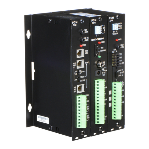
PCMCPU – Central processor
PCMTIM
–
Telephone interface
PCMZPM – Zone module (3 zones)
The PCMCPU module includes a set of DIP switches to set the
system ID, a Program/Run switch that allows system program-
ming, a Power jack for 12V DC power, and audio connections
for central amplifier, low-power BGM, high-power BGM, emer-
gency/shift change trigger, and auxiliary trigger.
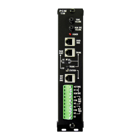
The PCMTIM telephone interface module incorporates a uni-
versal interface so that connection to any telephone system is
rapid and trouble-free.The module connects to the telephone
system via a standard RJ11 plug and is programmed simply by
using common DIP switches.All other connections are made to
built-in terminal blocks using only a small screwdriver.
Setup is also easy. Zone group programming, selection of all sig-
naling functions, and all other parameters are set by simply dial-
ing in with a touch-tone telephone.
The telephone interface module is equipped with three RJ11
jacks for Night Ring, Tel Line, and Override. The NIGHT
RINGER feature can be activated from 90V ring signal or con-
tact closure.The TEL LINE jack can be used to program the sys-
tem locally and provides 48V talk battery.The OVERRIDE fea-
ture permits all-zone override paging from a dedicated tele-
phone, trunk, or microphone (with suitable pre-amp).
The PCMZPM – zone paging module can operate high-power
or low-power paging systems (only one type per PCMZPM
module). For high-power paging, a single amplifier can be used
for paging and supplying background music (when not paging).
Background music can also be continuously supplied to all
zones not being paged with the addition of a second amplifier.
For low-power operation, background music is always supplied
to zones not being paged. Each module can also be discon-
nected from the background music bus and connected to a
local background music source.
Two additional zone modules can be added to the basic system
to increase capacity to 9 zones.When more than 9 zones are
required, a central processor module with power supply and up
to 3 zone modules can be assembled as a satellite system.Ten
additional 9-zone satellite systems can be installed to bring
total capacity to 99 zones.
A talkback module (PCMTBM) can also be added to the system
to provide hands-free talkback capability. Only one talkback
module is required regardless of the number of zones or satel-
lite systems on the PCM2000 system.
Relay driver outputs are provided for each zone. Two C-form
contact sets are also provided to control the activation of
accessory equipment.
Description

Architect & Engineer Specifications*
The zone paging system shall be the Bogen PCM2000 Zone
Paging System, designed for direct connection to loop start and
ground start trunks, to PBX or KEY paging ports which supply
DTMF capability, and to analog T/R lines. The unit shall allow
total system amplifier power of up to 250W.
The unit shall include flanges with keyhole slots for wall-mount-
ed installation. Operation shall require a 12V (1.5A) DC power
supply. A suitable power supply shall be provided (PCMPS2
power supply).
The system shall consist of the appropriate modules as speci-
fied and shall be registered under Part 68 of FCC rules.
Modules
All modules shall be designed for wall-mounted installation.All
modules shall be equipped with a ribbon cable and connector
and power cable with connector to permit them to be inter-
connected to each other.The face plates of each module shall
be finished in black, with each control/connector clearly labeled
in white. Each face plate shall have knockouts to facilitate cable
and wire dressing. All connections shall be made using a small
regular screwdriver or common jacks (RJ11 or RCA).
The following modules shall be available:
PCMTIM - Telephone Interface Module. One PCMTIM mod-
ule shall be provided per PCM2000 system. The module shall
provide for telephone interface selection via built-in DIP
switches. It shall include a volume control for tone and BGM
source, and RJ11 jacks for night ringer, telephone line, and over-
ride.A connector block, using screw terminal connections, shall
be provided for BGM source, and two (2) C-form relay contact
sets. A power-on LED indicator shall be provided to indicate
power-applied status.
PCMCPU - Central Processing Module. One PCMCPU mod-
ule shall be provided for the first nine (9) zones in the system.
One PCMCPU module shall be needed for each satellite sys-
tem.
The module shall provide for satellite system identification via
built-in DIP switches. It shall include a locking program/run
selector switch (with program LED), satellite data link RCA
jack, and 12V DC power source jack.A connector block, using
screw terminal connections, shall be provided for paging ampli-
fication connection, low-power and high-power BGM connec-
tions, emergency/shift change signal activation, AUX contact
closure, and 12V DC power source connection. A power-on
LED indicator shall be provided to indicate power-applied sta-
tus.
PCMZPM - Zone Paging Module. One PCMZPM module shall
be provided for each three (3) paging zones in the system. Up
to three (3) PCMZPM modules may be connected to the mas-
ter system, for a total zone capacity of 9 zones. Up to three (3)
additional PCMZPM modules may be connected with a PCM-
CPU module to form a satellite system to further increase
zone capacity.
The PCMZPM module shall provide built-in DIP switches to set
talkback on/off for each zone. It shall include a power-on LED,
low-power background music volume control, background
music out/in jumper field, local BGM selection jumpers, and
high-power/low-power operation selector switch.A connector
block, using screw terminal connections, shall be included to
connect local background music, zone wiring, and relay driver
outputs.
PCMTBM - Talkback Module. One PCMTBM talkback module
shall be provided per system (including any satellite systems).
The module shall provide for talkback operation in centrally-
amplified zones (only). The module shall provide a power-on
LED, talkback volume control, and talkback switching delay con-
trol.A connector block, using screw terminal connectors shall
be included for paging amplification wiring.
The PCM Zone Paging System shall supply the following fea-
tures and functions:
1. Simultaneous high-power and low-power paging.Total sys-
tem high-power audio capacity of 250W.
* Architect and Engineer Specifications are available on CD and online in
a Word document to assist you with preparing your bids.

2. A minimum of three paging zones and maximum zone capac-
ity of ninety-nine (99) paging zones. The system shall be
expandable in groups of three zones.
3. Up to 32 field-programmable paging zone groups, each con-
sisting of 1to 99 zones.
4. Field programmable Night Ringer Zone Group, consisting of
from 1to 99 zones.This feature shall be activated by high-
voltage ring signal or contact closure.
5. Field programmable Emergency/Shift change Zone Group,
consisting of from 1to 99 zones. This feature shall require
activation by a customer-supplied contact closure, and sound
a user-selected tone. The user shall have the choice of no
tone (allowing use of outside tone source), tone burst (1-7
sec. duration, user-selected), single chime, or quad beep.
6. Emergency All-Facility Page Override. This feature shall be
activated through a loop start trunk or through contact clo-
sure and dry audio input. It shall override the normal paging
features of the system, sound a user-defeatable alert tone in
all zones, and open an audio channel for a voice page.
7. Built-in, talkback amplification of central-amplified zones.
This feature shall require the addition of the PCMTBM mod-
ule.
8. Background music assigned per zone and local background
music sourcing capability.
9. Field programmable Code Call Zone Group, consisting of
from 1to 99 zones.The user shall have the choice of pattern
or echo code calls, and repeat functions.
10. Eight daily time-triggered signaling events. This feature
requires the use of the PCMTBM module.
11. Two (2) C-form relay contact sets for activating external
equipment.The contacts shall change state when the unit is
activated.
12. Capability of providing uninterrupted background music to
all zones not being paged.
13. Non-volatile RAM shall be included to allow for retention of
programming information during power interruptions
14. Screwdriver-adjustable volume control of confirmation, pre-
announce, error, and shift change/emergency-call tones.
50 Spring Street, Ramsey, NJ 07446
201-934-8500 FAX: 201-934-9832 www.bogen.com
Architect & Engineer Specifications, cont.
Other manuals for PCM2000
5
Table of contents
Other Bogen Microphone manuals