Operating Instructions
ON
Channel Selection – Handheld TChannel Selection – Handheld T
Channel Selection – Handheld TChannel Selection – Handheld T
Channel Selection – Handheld Transmitterransmitter
ransmitterransmitter
ransmitter
Once a channel has been selected on the receiver, you now need to select that same
channel on the handheld transmitter.
If you have a belt-pack transmitter, go to page 14 for
channel selection instructions.
ON
LCD
Display
LOCK SET
HM-900
SET
LOCK
UP
DOWN
Red
LED
ON/OFF
Switch
CH: 002
CH: 002
720.500M
LS
HM-900
SENS SET
LEVEL [2]
NiMH
AKLN
Setup Screens
selectable with
the UP and DOWN
Arrow Buttons
Wireless Transmitter
Handheld Microphone
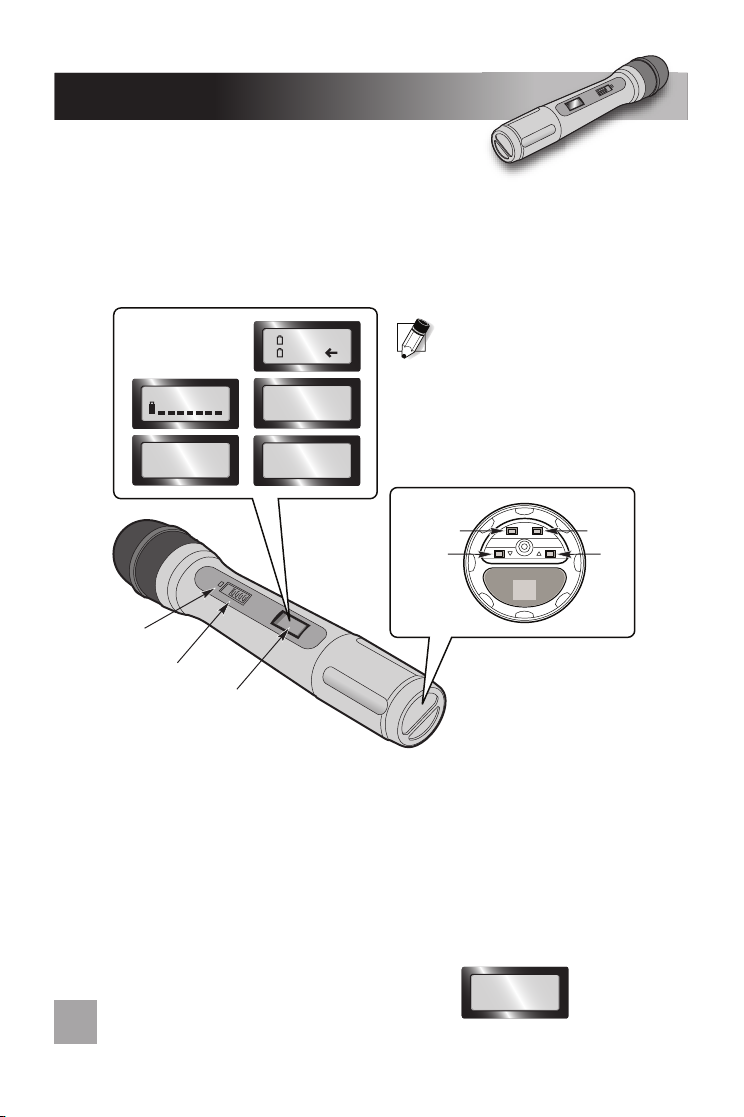
• Turn the microphone on by sliding
the switch on the barrel to the ON position. The red LED will flash once.
• To change the channel, press and hold the “SET” button on the bottom of the
microphone until there is a blinking cursor on the LCD display window
(approximately 3 seconds).
• Use the “UP” and “DOWN” Arrows to set the channel to match the receiver.
• Press and hold the “SET” button again until the blinking cursor disappears and the red
LED flashes
(approximately 3 seconds).
TT
TT
Transmission Frequency in MHz:ransmission Frequency in MHz:
ransmission Frequency in MHz:ransmission Frequency in MHz:
ransmission Frequency in MHz: Press the “UP”
button once to view the transmission frequency in
MHz of the currently selected channel.
9
NOTE: Transmitters and receivers
are available in 5 different frequency
groups. Verify that the letter code that
blinks on the receiver (when powered
ON) matches the letter code on the
frequency sticker in the battery
compartment of the transmitter.
Trouble Shooting Guide
No sound when someone speaks into the wireless microphone:
1.
7100DX system should be plugged into AC power and turned on.
The receiver module
should be set to the same channel as the transmitter.
2.
Microphone/transmitter power should be turned on.
If the LCD display does not
show, the batteries are most likely too weak. Replace with alkaline batteries.
• If NiMH rechargeable batteries are installed, plug in the charger. Otherwise,
replace with new alkaline batteries.
If you have gone through this trouble shooting guide and are still having problems, write
down the serial numbers of your system and call the LightSPEED Service Department at
1-800-732-8999
7:00 am - 5:00 pm PST
WARNING: Do not attempt to charge alkaline batteries. They can overheat
and expand, creating a significant hazard and damaging the transmitter.
(This is not covered by warranty.)
3. Verify the receiver and transmitter are in the same frequency group.
• Turn the receiver module off and on again. The letter code for the frequency group
will blink.
• Open the battery compartment on the transmitter to find the frequency group sticker.
4. Make sure the Mute light (on the belt-pack transmitter) is not flashing.
The wireless microphone is experiencing drop-out or interference:
1.
The wireless frequency being used may not be a clear channel:The wireless frequency being used may not be a clear channel:
The wireless frequency being used may not be a clear channel:The wireless frequency being used may not be a clear channel:
The wireless frequency being used may not be a clear channel:
Turn the transmit-
ter off and press the SCAN button on the receiver to find a clear frequency. Then
make sure to select the same channel on the transmitter.
2.
Squelch adjust on the receiver is set too high:Squelch adjust on the receiver is set too high:
Squelch adjust on the receiver is set too high:Squelch adjust on the receiver is set too high:
Squelch adjust on the receiver is set too high:
If this squelch is set too high (fully
clockwise), this can drastically reduce the range of the transmitter, resulting in more
frequent dropout.
3.
Squelch adjustment is set too low:Squelch adjustment is set too low:
Squelch adjustment is set too low:Squelch adjustment is set too low:
Squelch adjustment is set too low:
In areas of severe interference (large downtown
urban areas, airports, military bases, etc) it may be necessary to turn the squelch
up slightly to avoid outside interference.
4.
TT
TT
Transmitter is out of range of receiver:ransmitter is out of range of receiver:
ransmitter is out of range of receiver:ransmitter is out of range of receiver:
ransmitter is out of range of receiver:
The transmitters do have a maximum range
of about 300-350 feet in an open field environment. This range can be dramatically
reduced indoors and when large objects (such as a wall) may be obstructing the
path directly between transmitter and receiver. If this is the case, it may be
necessary to position the two closer together.
5.
Batteries are verBatteries are ver
Batteries are verBatteries are ver
Batteries are very weak:y weak:
y weak:y weak:
y weak:
Right before the batteries are about to die, it can
drastically affect the overall performance of the system. Make sure to check the
battery status of the transmitter (belt-pack or handheld).
18
• Use the “up” and “down” buttons to select a screen that shows the current channel.
CH: 002
720.500M