Bolens BL250 User manual

Today,homeownersaroundthecountryrely
onBolensfordurable,reliablepower
equipmentatanaffordableprice.
Operator’s
Manual
2-CycleGasTrimmer/Brushcutter
Model BL250
Sinceitbeganmakinggardentoolsin
1850,Bolenshasbeenknownforlong-
lasting,dependableproducts.Bolens
eventuallycarriedthathard-working
heritageintotheoutdoorpower
equipmentindustry,whenitdesigned
andbuiltthefirst-everpower-driven
gardentractor.

2
INTRODUCTION
THANKYOU
Thankyou for buying this quality product. This modern
outdoorpower tool will provide many hours of useful service.
Youwill find it to be a great labor-saving device. This
operator’smanual provides you with easy-to-understand
operatinginstructions. Read the whole manual and follow all
theinstructions to keep your new outdoor power tool in top
operatingcondition.
PRODUCT REFERENCES,ILLUSTRATIONS AND
SPECIFICATIONS
Allinformation, illustrations, and specifications in this manual
arebased on the latest product information available at the
timeof printing. We reserve the right to make changes at any
timewithout notice.
BumpHead™ is a trademark of MTD SOUTHWEST INC.
SplitLine™is a trademark of MTD SOUTHWEST INC.
Copyright©2004 MTD SOUTHWEST INC, All Rights Reserved.
SERVICE INFORMATION
Serviceon this unit both within and after the warranty period
shouldbe performed only by an authorized and approved
servicedealer.
For service call 1-800-520-5520 toobtain a list of authorized
servicedealers near you.
DONOT RETURN THE UNIT TO THE RETAILER. PROOF OF
PURCHASEWILL BE REQUIRED FOR WARRANTY SERVICE.
Beforebeginning, locate the unit’s model plate. It lists the
modeland serial numbers of your unit. Refer to the sample plate
belowand copy the information for future reference.
S/N : ITEM :
MODEL :
Copy the model / parent part
number here:
Copy the serial number here:
Makesureyoucarefullyreadandunderstandthismanualbefore
startingoroperatingthisequipment.
THISPRODUCT IS COVERED BY ONE OR MORE U.S. PATENTS.
OTHERPATENTS PENDING.
WARNING
TABLE OF CONTENTS
ServiceInformation . . . . . . . . . . . . . . . . . . . . . . . . . . . . . . .. . . .2
Rulesfor Safe Operation . . . . . . . . . . . . . . . . . . . . . . . . . . . . .. .3
KnowYour Unit . . . . . . . . . . . . . . . . . . . . . . . . . . . . . .. . . . . . . . .6
AssemblyInstructions . . . . . . . . . . . . . . . . . . . . . . . . . . . . . . .. .7
Oiland Fuel Information . . . . . . . . . . . . . . . . . . . . . . . . . . . . .10
Starting/StoppingInstructions . . . . . . . . . . . . . . . . . . . . . . .11
OperatingInstructions . . . . . . . . . . . . . . . . . . . . . . . . . . . . . . .12
Maintenanceand Repair Instructions . . . . . . . . . . . . . . . . .14
Cleaningand Storage . . . . . . . . . . . . . . . . . . . . . . . . . . . . . .. .19
TroubleshootingChart . . . . . . . . . . . . . . . . . . . . . . . . . . . . . . .20
Specifications .. . . . . . . . . . . . . . . . . . . . . . . . . . . . . . .. . . . . . . .21
WarrantyInformation . . . . . . . . . . . . . . . . . . . . . . . . . . . . . . ..26
PartsList . . . . . . . . . . . . . . . . . . . . . . . . . . . . .Inside Back Coverr
SPARK ARRESTOR NOTE
NOTE: For users on U.S. Forest Land and in the states of
California, Maine, Oregon, and Washington. All U.S. Forest
Land and the state of California (Public Resources Codes 4442
and 4443), Oregon, and Washington require by law that cer-
tain internal combustion engines operated on forest brush
and/or grass-covered areas be equipped with a spark
arrestor, maintained in effective working order, or the engine
be constructed, equipped, and maintained for the prevention
of fire. Check with your state or local authorities for regula-
tions pertaining to these requirements. Failure to follow
these requirements could subject you to liability or a fine.
This unit is factory equipped with a spark arrestor. If it
requires replacement, ask your LOCAL SERVICE DEALER to
install the Accessory Part #182747 Spark Arrestor.
THE ENGINE EXHAUST FROMTHIS PRODUCT
CONTAINS CHEMICALS KNOWNTOTHE STATE
OF CALIFORNIATO CAUSE CANCER,BIRTH
DEFECTS,OR OTHER REPRODUCTIVE HARM
.
CALIFORNIA PROPOSITION 65WARNING

3
RULESFORSAFEOPERATION
BEFORE OPERATING
•Read the instructions carefully. Be familiar with the controls
andproper use of the unit.
•Do not operate this unit when tired, ill or under the influ-
enceof alcohol, drugs or medication.
•Children under the age of 15 must not use the unit; teens
mayoperate the unit with adult guidance.
•Inspect the unit before use. Replace damaged parts. Check
for fuel leaks. Make sure all fasteners are in place and
secure. Replace cutting attachment parts that are cracked,
chipped or damaged in any way. Make sure the cutting
attachment is properly installed and securely fastened. Be
sure that the cutting attachment shield is properly
attached, and positioned as recommended. Failure to do so
can result in personal injury to the operator and
bystanders,as well as damage to the unit.
•Use only 0.095-inch (2.41 mm) diameter original equip-
ment manufacturer replacement line. Never use metal-rein-
forced line, wire, chain or rope. These can break off and
becomedangerous projectiles.
•Beaware of risk of injury to the head, hands and feet.
•Squeeze the throttle control and check that it returns auto-
matically to the idle position. Make all adjustments or
repairsbefore using the unit.
•Clear the area to be cut before each use. Remove rocks,
broken glass, nails, wire, string and other objects which
may be thrown or become entangled in the cutting attach-
ment. Clear the area of children, bystanders and pets; keep
them outside a 50-foot (15 m.) radius, at a minimum. Even
then, they are still at risk from thrown objects. Encourage
bystanders to wear eye protection. If you are approached,
stopthe unit immediately.
•Add fuel in a clean, well-ventilated outdoor area where
there are no sparks or flames. Remove the fuel cap slowly,
and only after the engine stops. Do not smoke while fuel-
ing or mixing fuel. Wipe up any spilled fuel from the unit
immediately.
SAFETYWARNINGS FOR GAS TRIMMERS
•Store fuel only in containers specifically designed and
approvedfor the storage of such materials.
•Always stop the engine and allow it to cool before filling
the fuel tank. Never remove the fuel tank cap or add fuel
when the engine is hot. Never operate the unit without the
fuel cap securely in place. Loosen the fuel tank cap slowly
torelieve any pressure in the tank.
Read the Operator’s Manual(s) and follow all warnings and safety instructions.
Failure to do so can result in serious injury to the operator and/or bystanders.
FOR QUESTIONS,CALL 1-800-520-5520
• SAFETY SYMBOLS •
• IMPORTANT SAFETY INFORMATION •
READ ALL INSTRUCTIONS
The purpose of safety symbols is to attract your attention to possible dangers. The safety symbols, and their explanations, deserve
your careful attention and understanding. The safety warnings do not by themselves eliminate any danger. The instructions or
warningsthey give are not substitutes for proper accident prevention measures.
SYMBOL MEANING SYMBOL MEANING
NOTE: Advises you of information or instructions vital to the operation or maintenance of the equipment.
Failure to obey a safety
warning can result in
injury to yourself and others. Always follow the
safety precautions to reduce the risk of fire, elec-
tricshock and personal injury.
WARNING:
Failure to obey a safety
warning will result in seri-
ous injury to yourself or to others. Always follow
the safety precautions to reduce the risk of fire,
electricshock andpersonal injury.
DANGER: Failure to obey a safety
warning may result in
property damage or personal injury to yourself
or to others. Always follow the safety precau-
tions to reduce the risk of fire, electric shock and
personalinjury.
CAUTION:
Indicates dan-
ger, warning
or caution. Attention is required in order to
avoid serious personal injury. May be used in
conjunctionwith other symbols or pictographs.
SAFETY ALERT:
Gasoline is highly flam-
mable and its vapors can
explodeifignited.Followtheensuingprecautions.
WARNING:
When using the unit, you
must follow the safety
rules. Please read these instructions before operat-
ing the unit in order to ensure the safety of the
operator and any bystanders. Please keep these
instructionsfor later use.
WARNING:

4
•Avoid creating a source of ignition for spilled fuel. Do not
startthe engine until fuel vapors dissipate.
•Move the unit at least 30 feet (9.1 m) from the fueling
source and site before starting the engine. Do not smoke.
Keep sparks and open flames away from the area while
addingfuel or operating the unit.
WHILE OPERATING
•Never start or run the unit inside a closed room or building.
Breathing exhaust fumes can be fatal. Operate this unit
onlyin a well-ventilated outdoor area.
•Wear safety glasses or goggles that meet ANSI Z87.1 stan-
dards and are marked as such. Wear ear/hearing protection
when operating this unit. Wear a face or dust mask if the
operationis dusty.
•Wear heavy long pants, boots, gloves and a long sleeve
shirt. Do not wear loose clothing, jewelry, short pants, san-
dalsor go barefoot. Secure hair above shoulder level.
•The cutting attachment shield must always be in place while
operating the unit. Do not operate unit without both trim-
ming lines extended, and the proper line installed. Do not
extendthe trimming line beyond the length of the shield.
•This unit has a clutch. The cutting attachment remains sta-
tionary when the engine is idling. If it does not, have the
unitadjusted by an authorized service technician.
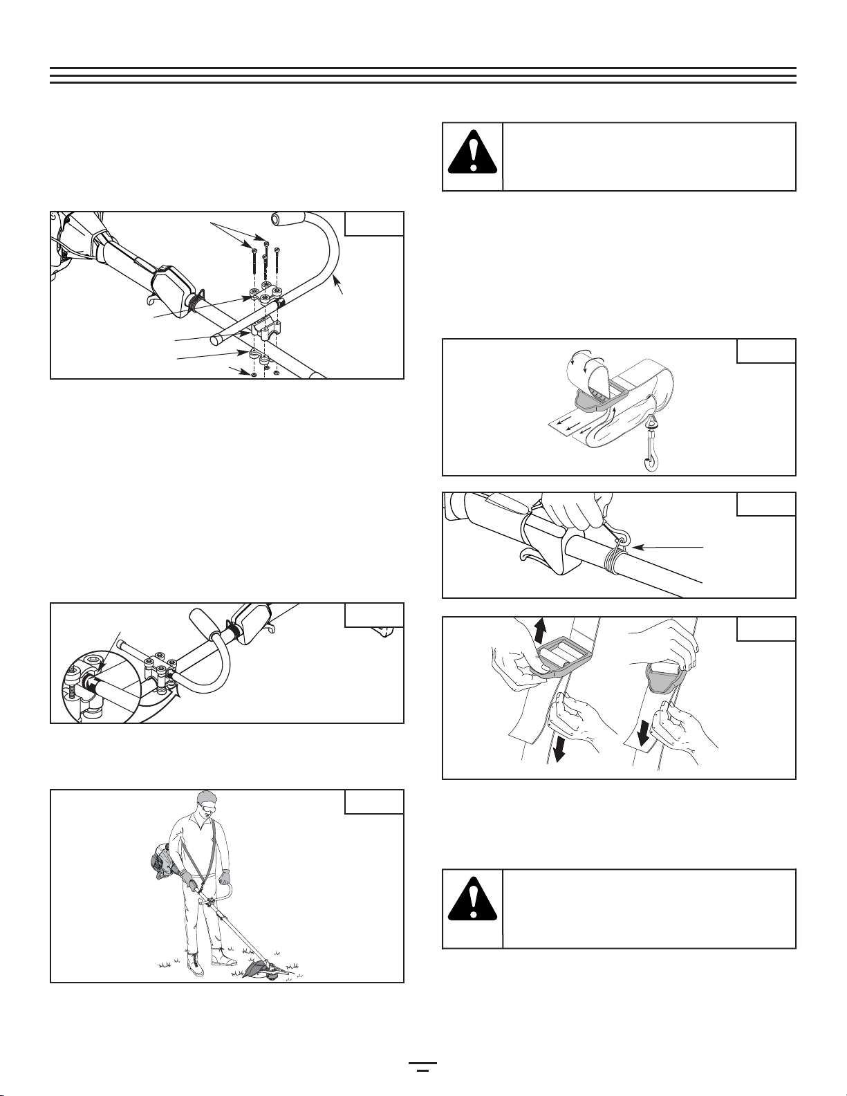
•Adjust the J-handle to your size in order to provide the best
grip.
•Be sure the cutting attachment is not in contact with any-
thingbefore starting the unit.
•Usethe unit only in daylight or good artificial light.
•Avoid accidental starting. Be in the starting position when-
ever pulling the starter rope. Both the operator and unit
must be in a stable position while starting. Refer to the
Starting/StoppingInstructions.
•Usethe right tool. Only use this tool for its intended purpose.
•Donot overreach. Always keep proper footing and balance.
•Always hold the unit with both hands when operating.
Keepa firm grip on both handles or grips.
•Keep hands, face, and feet at a distance from all moving
parts. Do not touch or try to stop the cutting attachment
whenit rotates.
•Do not touch the engine, gear housing or muffler. These
parts get extremely hot from operation, even after the unit
isturned off.
•Do not operate the engine faster than the speed needed to
cut, trim or edge. Do not run the engine at high speed
whennot cutting.
•Always stop the engine when cutting is delayed or when
walkingfrom one cutting location to another.
•If you strike or become entangled with a foreign object,
stop the engine immediately and check for damage. Do
not operate before repairing damage. Do not operate the
unitwith loose or damaged parts.
•Stop the unit, switch the engine to off, and disconnect the
sparkplug for maintenance or repair.
•Use only original equipment manufacturer replacement
parts and accessories for this unit. These are available from
your authorized service dealer. Use of any non-original fac-
tory parts or accessories could lead to serious injury to the
user,or damage to the unit, and void your warranty.
•Keep unit clean of vegetation and other materials. They may
becomelodged between the cutting attachment and shield
.
•To reduce fire hazard, replace a faulty muffler and spark
arrestor. Keep the engine and muffler free from grass,
leaves,excessive grease or carbon build up.
WHILE OPERATINGWITH CUTTING BLADE
•Read and understand all safety warnings before operating
thisunit.
•Always use the shoulder harness when using the brush
bladeaccessory.
•Keep the J-handle between the operator and cutting
attachmentor blade at all times.
•NEVER cut when the cutting blade is 30 inches (76 cm) or
moreabove the ground level.
•Blade thrust may occur when the spinning blade contacts
an object that it does not immediately cut. Blade thrust can
be violent enough to propel the unit and/or operator in
any direction, possibly causing a loss of control. Blade
thrust can occur without warning if the blade snags, stalls
or binds. This is more likely to occur in areas where it is dif-
ficultto see the material being cut.
•For operation with the brush blade, do not cut anything
thickerthan 1/2 inch or a violent kickback could occur.
•Donot attempt to touch or stop the blade when it is rotating.
•Acoasting blade can cause injury while it continues to spin
after the engine is stopped or the throttle trigger is
released. Maintain proper control until the blade has com-
pletelystopped rotating.
•Donot run the unit at high speed when not cutting.
•If you strike or become entangled with a foreign object, stop
the engine immediately and check for damage. Have any
damage repaired before attempting further operations. Do
not operate unit with a bent, cracked or dull blade. Discard
bladesthat are bent, warped, cracked or broken.
•Do not sharpen the cutting blade. Sharpening the blade
can cause the blade tip to break off while in use. This can
resultin severe personal injury. Replace the blade.
•Do not use the cutting blade for edging or as an edger; severe
personal injury to yourself or others may incur. Use the cutting
bladeonly for the purpose as described in this manual.
•Stop the engine IMMEDIATELY if you feel excessive vibra-
tion. Vibration is a sign of trouble. Inspect thoroughly for
loose nuts, bolts or damage before continuing. Repair or
replaceaffected parts as necessary.
After Use
•Clean cutting blades with a household cleaner to remove any
gumbuildup. Oil the blade with machine oil to prevent rust.
•Lock up and store the cutting blade in an appropriate area
toprotect the blade from unauthorized use or damage.
OTHER SAFETYWARNINGS
•Never store a fueled unit inside a building where fumes
mayreach an open flame or spark.
•Allow the engine to cool before storing or transporting. Be
sureto secure the unit while transporting.
•Store the unit in a dry area, locked up or up high to prevent
unauthorizeduse or damage, out of the reach of children.
•Never douse or squirt the unit with water or any other liq-
uid. Keep handles dry, clean and free from debris. Clean
after each use, see CleaningandStorage instructions.
•Keep these instructions. Refer to them often and use them
to instruct other users. If you loan someone this unit, also
loanthem these instructions.
SAVETHESE
INSTRUCTIONS
RULESFORSAFEOPERATION

5
SYMBOL MEANING
•THROWN OBJECTS AND ROTATING
CUTTER CAN CAUSE SEVERE
INJURY
WARNING: Donot operate without the
cuttingattachment shield in place.
Keepaway from the rotating cutting
attachment.
•HOT SURFACEWARNING
Donot touch a hot muffler, gear housing
orcylinder. You may get burned. These
partsget extremely hot from operation.
Theyremain hot for a short time after the
unitis turned off.
•SHARP BLADE
WARNING: Sharpblade on cutting
attachmentshield. To prevent serious
injury,do not touch line cutting blade.
•CHOKE CONTROL
1 • FULL chokeposition
2 • PARTIAL chokeposition
3 • RUN position
•BRUSHCUTTERS • REPLACE DULL
BLADES
Donot sharpen the cutting blade.
Sharpeningthe blade can cause the
bladetip to break off while in use. This
canresult in severe personal injury.
•TRIMMER/BRUSHCUTTER SAFETY
WARNING: Thrownobjects and rotating
cuttercan cause severe injury. Keep
bystanders,especially children and pets,
atleast 50 feet (15 m) away from the
cuttingarea. The cutting attachment
shieldmust be used when using the
trimmercutting attachment.
SYMBOL MEANING
•SAFETY ALERT SYMBOL
Indicatesdanger, warning or caution.
Maybe used in conjunction with other
symbolsor pictographs.
•WARNING - READ OPERATOR'S
MANUAL
Readthe operator’s manual(s) and follow
allwarnings and safety instructions.
Failureto do so can result in serious
injuryto the operator and/or bystanders.
•WEAR EYE AND HEARING
PROTECTION
WARNING: Thrownobjects and loud
noisecan cause severe eye injury and
hearingloss. Wear eye protection
meetingANSI Z87.1 standards and ear
protectionwhen operating this unit. Use
afull face shield when needed.
•KEEP BYSTANDERS AWAY
WARNING: Keepall bystanders,
especiallychildren and pets, at least 50
feet(15 m) from the operating area.
•UNLEADED FUEL
Alwaysuse clean, fresh unleaded fuel.
•OIL
Referto operator's manual for the proper
typeof oil.
•ON/OFF STOP CONTROL
ON/ START / RUN
•ON/OFF STOP CONTROL
OFFor STOP
SAFETY AND INTERNATIONAL SYMBOLS
Thisoperator's manual describes safety and international symbols and pictographs that may appear on this product.
Readthe operator's manual for complete safety, assembly, operating and maintenance and repair information.
123
RULESFORSAFEOPERATION

6
Applications
Asa trimmer:
•Cuttinggrass and light weeds
•Edging
•Decorativetrimming around trees, fences, etc.
Asa brushcutter:
•Cuttingweeds and light bush of up to 1/2 inch in
diameter
Cutting Attachment Shield
Fuel Cap
Throttle
Control J-Handle
Cutting Attachment
Gear Housing
Shaft Grip
Primer Bulb
Blue Lever
Air Filter/Muffler
Cover
Spark Plug
On/Off Stop Control
Shaft
Housing
Starter Rope Grip
KNOWYOUR UNIT
Blade Shield /
Shield Mount
Cutting Blade
Line Cutting Blade
Muffler
Support Fitting
Throttle Lock-Out
Throttle Control
RULESFORSAFEOPERATION

7
Onsome units, the J-handle may be pre-installed. In this case
youmust loosen screws and adjust the handle to fit the
operator.Go to step 5 if the J-handle is pre-installed.
INSTALL AND ADJUSTTHE J-HANDLE
1. Placethe J-handle between the top and middle clamp
pieces(Fig. 1).
(4) Screws
Top Clamp J-Handle
Middle Clamp
Bottom Clamp Nuts
2. Whileholdingthethreepiecestogether,installthefour(4)
screwsthroughthetopclampandintomiddleclamp.
NOTE: The holes in the top and middle clamp will line
uponly when assembled correctly.
3. Placethe clamps and the J-handle over the shaft housing
andonto the bottom clamp.
4. Holdeach hex nut in the bottom clamp recess with a
finger.Start screws with a large Phillips screwdriver. Do
nottighten until you make the handle adjustment.
5. Slidethe J-handle in or out until the arrow/white line on
thedecal touches the clamp assembly (Fig. 2). You must
firstloosen the screws if the handle is pre-installed
.
6. Whileholdingthe unitinthe operatingposition(Fig. 3),
movetheJ-handle tothelocation thatprovidesyou the
bestgrip.
7. Tightenthe clamp screws evenly, until the J-handle is
secure.
Decal
INSTALLTHE HARNESS
1. Pushthe strap through the center of the buckle.
2. Pullthe strap over the cross bar and down through the
slotin the buckle (Fig. 4).
3. Putthe harness on over your head and onto your
shoulder.Snap it on to the support fitting (Fig. 5).
4. Adjustthe length to fit the operator’s size. Pull the tab to
lengthen,pull the strap to shorten (Fig 6).
Support Fitting
REMOVE AND INSTALL THE CUTTING ATTACHMENT
SHIELD
Remove the cutting attachment shield when using the
unit as a brushcutter
Removethe cutting attachment shield from the shield
mountby removing the three (3) screws with a flat blade
screwdriver(Fig. 7). Store parts for future use.
ASSEMBLYINSTRUCTIONS
Fig.1
Fig.6
Fig.5
Fig.4
Fig.3
Fig.2
The cutting attach-
ment shield should
NOT be installed when operating the unit with a
blade. Remove the cutting attachment shield
beforeremoving or installing the blade.
WARNING:
Always use the shoul-
der harness when
using the cutting blade to avoid serious person-
alinjury.
WARNING:

8
Install the cutting attachment shield when using the unit
as a grass trimmer
Installthe cutting attachment shield on the shield mount by
insertingthe three (3) screws into the shield mount. Tighten
securelywith a flat blade screwdriver (Fig. 7).
REMOVETHE CUTTING ATTACHMENT AND INSTALL
THE CUTTING BLADE
NOTE:
To make cutting blade removal and installation easi-
er,placetheunitonthe ground or onaworkbench
.
Remove the Cutting Attachment Shield
See RemoveandInstalltheCuttingAttachmentShield.
Remove the Cutting Attachment
1.
Aligntheshaft bushingholewith thelockingrod slotand
insertthelocking rodintothe shaftbushinghole (Fig.8).
(3) Screws
Cutting
Attachment
Shield
Shield Mount
Gear Housing
Cutting Attachment
Locking Rod
Slot
Locking Rod
Shaft Bushing Hole
Locking Rod Slot
Output Shaft
Bushing
Locking Rod
Output
Shaft
2. Holdthe locking rod in place by grasping it next to the
boomof the unit (Fig. 9).
3. Whileholding thelocking rod,remove the cutting
attachmentby turningit clockwiseoff of the output shaft
(Fig.10). Storethe cuttingattachment for future use.
NOTE: The blade retainer under the cutting attachment
willbe used when installing the cutting blade.
Install the Cutting Blade
4
.Placethe cutting blade on the output shaft bushing (Fig. 11).
Shield
Mount
Locking Rod
Cutting
Blade
Blade Retainer Nut
Output Shaft
Bushing
Pilot Hole
ASSEMBLYINSTRUCTIONS
Fig.11
Fig.10
Fig.9
Fig.8
Fig.7
The gear housing gets
hot with use. It can
result in injury to the operator. The housing
remains hot for a short time even after the unit
is turned off. Do not touch the gear housing
untilit has cooled.
WARNING:
To avoid serious per-
sonal injury, the cutting
attachment shield MUST be in place at all times
whileoperatingthe unitasa grasstrimmer.
WARNING:
To avoid serious person-
al injury, always wear
gloveswhilehandlingorinstallingthe blade.
WARNING:

9
Pilot Step
REMOVETHE CUTTING BLADE AND INSTALLTHE
CUTTING ATTACHMENT
Remove the Cutting Blade
1. Aligntheshaft bushingholewith thelockingrod slotand
insertthelocking rodintothe bushinghole(Fig. 8).
2. Holdthe locking rod in place by grasping it next to the
boomof the unit (Fig. 14).
3. Whileholding the locking rod, loosen the nut on the
bladeby turning it clockwise with a 5/8 inch closed-end
orsocket wrench (Fig. 14).
9. Removethe locking rod from the locking rod slot.
1/4-1/2 turn
Counterclockwise
6. Alignthe shaft bushing hole with the locking rod slot and
insertthe locking rod into the bushing hole (Fig. 8).
7. Putthe blade retainer and nut on the output shaft. Make
surethat the blade is installed correctly.
8. Tightennut counterclockwise against the blade while
holdingthe locking rod:
•
Ifusing a torque wrench and an 5/8 inch socket, tighten to:
325 - 335 in•lb, 27 - 28 ft.•lb, 37 - 38 N•m.
•Withouta torque wrench, use a 5/8 inch closed-end or
socketwrench, turning the nut until the blade retainer is
snugagainst the shaft bushing. Make sure that the blade
isinstalled correctly, then rotate the nut an additional 1/4
to1/2 turn counterclockwise (Fig. 13).
Cutting Attachment
Locking Rod
Clockwise
6. Removethe locking rod.
7. Installthe cutting attachment shield. Refer to Removeand
InstalltheCuttingAttachmentShield.
Blade Retainer
Output Shaft
Bushing
5. Makesure that the cutting blade is centered on the pilot
stepand sitting flat against the output shaft bushing
(Fig.12).
4. Removethe nut, blade retainer and blade. Store the nut
andblade together for future use in a secure place. Store
outof children’s reach.
Install the Cutting Attachment
5.
Alignthe shaftbushing holewith the locking rod slot and
insertthe lockingrod intothe shaft bushing hole (Fig. 8).
Placethe bladeretainer onthe output shaft with the flat
surfaceagainst theoutput shaftbushing as shown in Fig. 15.
Screwthe cuttingattachment counterclockwiseonto the
outputshaft. Tightensecurely.
NOTE: The blade retainer must be installed on the out-
put shaft in the position shown for the cutting
attachmentto work correctly.
ASSEMBLYINSTRUCTIONS
Fig.15
Fig.14
Fig.13
Fig.12
If the cutting blade is
off-center, the unit will
vibrate and the blade may fly off, causing possi-
bleserious personal injury.
WARNING: To avoid serious person-
al injury, always wear
gloveswhilehandlingorinstallingthe blade.
WARNING:
Do not sharpen the cut-
ting blade. Sharpening
the blade can cause the blade tip to break off while
in use. This can result in severe personal injury.
Replacethe blade.
WARNING:
To avoid serious personal
injury or damage to the
unit, do not start or operate this unit with the lock-
ingrodinthelockingrodslot.
WARNING:
To avoid serious per-
sonal injury, the cut-
ting attachment shield MUST be in place at all
timeswhile operating the unit as a trimmer.
WARNING:

10
OIL&FUELINFORMATION
NOTE: Dispose of the old fuel/oil mix in accordance to
Federal,State and Local regulations.
OIL AND FUEL MIXING INSTRUCTIONS
Oldand/or improperly mixed fuel are the main reasons for
improperunit performance. Be sure to use fresh, clean
unleadedfuel. Follow the instructions carefully for the proper
fuel/oilmixture.
Definition of Blended Fuels
Today'sfuels are often a blend of gasoline and oxygenates
suchas ethanol, methanol, or MTBE (ether). Alcohol-blended
fuelabsorbs water. As little as 1% water in the fuel can make
fueland oil separate. It forms acids when stored. When using
alcohol-blendedfuel, use fresh fuel (less than 60 days old).
Using Blended Fuels
Ifyou choose to use a blended fuel, or its use is unavoidable,
followrecommended precautions:
•Alwaysuse the fresh fuel mix explained in your opera-
tor'smanual
•Alwaysagitate the fuel mix before fueling the unit
•Drainthe tank and run the engine dry before storing the
unit
Using Fuel Additives
Thebottle of 2-cycle oil that came with your unit contains a
fueladditive which will help inhibit corrosion and minimize
theformation of gum deposits. It is recommended that you
useour 2-cycle oil with this unit.
Ifunavailable, use a good 2-cycle oil designed for air-cooled
enginesalong with a fuel additive, such as STA-BIL® Gas
Stabilizeror an equivalent. Add 0.8 oz. (23 ml.) of fuel
additiveper gallon of fuel according to the instructions on
thecontainer. NEVER add fuel additives directly to the unit's
fueltank.
Thoroughlymix the proper ratio of 2-cycle engine oil with
unleadedgasoline in a separate fuel can. Use a 40:1 fuel/oil
ratio.Do not mix them directly in the engine fuel tank. See
thetable below for specific gas and oil mixing ratios.
NOTE: One gallon (3.8 liters) of unleaded gasoline
mixed with one 3.2 oz. (95 ml.) bottle of
2-cycleoil makes a 40:1 fuel/oil ratio.
UNLEADED GAS 2 CYCLE OIL
1 US. GALLON
(3.8 LITERS) 3.2 FL OZs.
(95 ml)
1 LITER 25 ml
+
MIXING RATIO = 40 : 1
Gasoline is extremely
flammable. Ignited Vapors
may explode. Always stop the engine and allow it
to cool before filling the fuel tank. Do not smoke
while filling the tank. Keep sparks and open flames
ata distance from the area.
WARNING:
Add fuel in a clean, well
ventilated area outdoors.
Wipe up any spilled fuel immediately. Avoid cre-
ating a source of ignition for spilt fuel. Do not
starttheengine untilfuelvapors dissipate.
WARNING:
Remove fuel cap slowly
to avoid injury from fuel
spray. Never operate the unit without the fuel cap
securelyin place
.
WARNING:
For proper engine opera-
tion and maximum relia-
bility, pay strict attention to the oil and fuel mix-
inginstructions on the2-cycle oil container. Using
improperly mixed fuel can severely damage the
engine.
CAUTION:

11
On/Off Stop Control
Start/On (I)
Stop/Off (O)
Throttle
Lock-Out
Throttle Control
Blue Lever
Position 1 Position 3
Position 2
Starter
Rope
Throttle Control
Primer Bulb
STARTING/STOPPINGINSTRUCTIONS
Fig.18
Fig.17
Fig.16
STARTING INSTRUCTIONS
Avoid accidental starting.
Make sure you are in the
starting position when pulling the starter rope (Fig. 18).
To avoid serious injury, both the operator and unit must
be in a stable position while starting.
WARNING:
Operate this unit only in a well-
ventilated outdoor area. Carbon
monoxideexhaustfumes can belethalinaconfinedarea.
WARNING:
STOPPING INSTRUCTIONS
1. Releaseyour hand from the throttle control. Allow the engine to
cooldown by idling.
2. Put the On/Off Stop Control in the OFF (O) position.
1. Mix gas with oil. Fill fuel tank with fuel/oil mixture. See Oil
andFuelMixing Instructions.
2. Make sure the On/Off Stop Control in the ON (I) position
(Fig. 16).
3. Fully press and release the primer bulb 10 times, slowly.
Some amount of fuel should be visible in the primer
bulb and fuel lines (Fig. 17). If you can’t see fuel in the bulb,
press and release the bulb as many times as it takes before
you can see fuel in it.
4. Place the blue lever in Position 1(Fig. 17).
5. Crouch in the starting position (Fig. 18) and squeeze the
throttle control. Pull the starter rope briskly 5 times (with
the blue lever still in Position 1).
6. Place the blue lever in Position 2.
7. While squeezing the throttle lock-out and throttle control,
pull the starter rope briskly 1 to 3 times to start the engine.
8. Keep the throttle squeezed and allow the engine to warm
up for 15 to 30 seconds.
9. Place the blue lever in Position 3. The unit is ready for use.
IF... The engine does not start, go back to step 3.
IF... The engine fails to start after a few attempts, place the
blue lever in Position 3and squeeze the throttle control.
Pull the starter rope briskly 3 to 8 times. The engine
should start. If not, repeat.
IFWARM... If the engine is already warm, make sure the
On/Off Stop control is in the ON position and start the
unit with the blue lever in Position 2. After the unit starts,
move the blue lever to Position 3.

12
HOLDINGTHETRIMMER
Beforeoperating the unit, stand in the operating position
(Fig.19). Check for the following:
•Theoperator is wearing eye protection and proper
clothing
•Witha slightly-bent right arm, the operator’s right hand
isholding the shaft grip
•Theoperator’s left arm is straight, the left hand holding
theJ-handle
•Theunit is at waist level
•Thecutting attachment is parallel to the ground and
easilycontacts the grass without the need to bend over
Onceyou are in the operating position, hook the shoulder
strapto the unit.
ADJUSTINGTRIMMING LINE LENGTH
TheBumpHead™ cuttingattachmentallows youtorelease
trimminglinewithout stoppingtheengine. Toreleasemore
line,lightlytap thecuttingattachment ontheground (Fig.20)
whileoperatingthe trimmerathigh speed.
NOTE:Always keep the trimming line fully extended.
Line release becomes more difficult as the cut-
tingline becomes shorter.
Eachtime the head is bumped, about 1 inch (25.4 mm) of
trimmingline is released. A blade in the cutting attachment
shieldwill cut the line to the proper length if excess line is
released.
Forbest results, tap the Bump Head™ on bare ground or hard
soil.If line release is attempted in tall grass, the engine may
stall.Always keep the trimming line fully extended. Line
releasebecomes more difficult as the cutting line becomes
shorter.
NOTE: Do not rest the Bump Head™ on the ground
whilethe unit is running.
Someline breakage will occur from:
•Entanglementwith foreign matter
•Normalline fatigue
•Attemptingto cut thick, stalky weeds
•Forcingtheline intoobjectssuch aswallsor fenceposts
TIPS FOR BESTTRIMMING RESULTS
•Forbest trimming results, operate unit at full throttle.
•Keepthe cutting attachment parallel to the ground.
•Donot force the cutting attachment. Allow the tip of the
lineto do the cutting, especially along walls. Cutting with
morethan the tip will reduce cutting efficiency and may
overloadthe engine.
•Cutgrass over 8 inches (200 mm) by working from top to
bottomin small increments to avoid premature line wear
orengine drag.
•Cutfrom left to right whenever possible. Cutting to the
rightimproves the unit's cutting efficiency. Clippings are
thrownaway from the operator.
•Slowlymove the trimmer into and out of the cutting area
atthe desired height. Move either in a forward-backward
orside-to-side motion. Cutting shorter lengths produces
thebest results.
•Trimonly when grass and weeds are dry.
•Thelife of your cutting line is dependent upon:
• Properadherence of trimming techniques (explained
above)
• Whatvegetation is cut
• Wherevegetation is cut
Forexample,thelinewillwearfasterwhentrimmingagainsta
foundationwallasopposedtotrimmingaroundatree.
OPERATINGINSTRUCTIONS
Fig.20
Fig.19
Always wear eye, hear-
ing, foot and body pro-
tection to reduce the risk of injury when operat-
ingthis unit.
WARNING:
Do not remove or alter the
line cutting blade assembly.
Excessive line length will make the clutch overheat.
This may lead to serious personal injury or damage
totheunit.
CAUTION:

13
DECORATIVETRIMMING
Decorativetrimming is accomplished by removing all
vegetationaround trees, posts, fences and more.
Rotatethe whole unit so that the cutting attachment is at a
30°angle to the ground (Fig. 21).
USINGTHE CUTTING BLADE
Beforeoperating the unit with the cutting blade, stand in the
operatingposition (Fig. 22). Refer to HoldingtheTrimmer.
Cutting Blade Operating Tips
Toestablish a rhythmic cutting procedure:
•Plantfeet firmly, comfortably apart.
•Bringthe engine to full throttle before entering the
materialto be cut. At full throttle the blade has maximum
cuttingpower and is less likely to bind, stall or cause
bladethrust (which can result in serious personal injury
tothe operator or others).
•Cutwhile swinging the upper part of your body from left
toright
•Alwaysrelease the throttle trigger and allow the engine
toreturn to idle speed when not cutting.
•Whenyou are finished, always unsnap the unit from the
harnessbefore taking off the harness.
•Swingthe unit in the opposite direction as the blade
spins,which increases the cutting action.
•Afterthe return swing, move forward to the next area to
becut plant your feet again.
•Thecutting blade is designed with a second cutting
edge.You can use it by removing the blade, turning it
upsidedown, and reinstalling it.
Toreduce the chance of material wrapping around the blade,
followthese steps:
•Cutat full throttle
•Swingthe unit into material to be cut from your left to
yourright (Fig. 23)
•Avoidthe materialjustcut asyou make thereturn swing
OPERATINGINSTRUCTIONS
Fig.23
Fig.22
Fig.21
Always wear eye, hear-
ing, foot, body protec-
tion and the shoulder strap to reduce the risk of
injurywhen operating this unit.
WARNING:
Do not use the cutting
blade for edging or as
an edger. Severe personal injury to yourself or
otherscan result.
WARNING:
The blade continues to
spin after the engine is
turned off. The coasting blade can seriously cut
youif accidentally touched.
WARNING:
Do not sharpen the cut-
ting blade. Sharpening
the blade can cause the blade tip to break off
while in use. This can result in severe personal
injuryto yourself or others. Replace the blade.
WARNING:
Bl
ade thrust may occur
when the spinning
blade contacts an object that it does not immedi-
ately cut. Blade thrust can be violent enough to
cause the unit and/or operator to be propelled in
any direction, and possibly lose control of the
unit. Blade thrust can occur without warning if the
blade snags, stalls or binds. This is more likely to
occur inareas where it is difficult to see the materi-
albeing cut.
WARNING:
Do not clear away any
cut material with the
engine running or blade turning. To avoid seri-
ous personal injury, turn off the engine. Allow
the blade to stop before removing materials
wrappedaround the blade shaft.
WARNING:

14
MAINTENANCE SCHEDULE
Performthese requiredmaintenance proceduresat the
frequencystated inthe table.These procedures should also
bea partof anyseasonal tune-up.
NOTE: Some maintenance procedures may require
special tools or skills. If you are unsure about
these procedures take your unit to any non-
road engine repair establishment, individual or
authorizedservice dealer.
NOTE: Maintenance, replacement, or repair of the emis-
sion control devices and system may be per-
formed by any non-road engine repair establish-
ment,individual or authorized service dealer.
Inorder to assure peak performance of your engine,
inspectionof the engine exhaust port may be necessary after
50hours of operation. If you notice lost RPM, poor
performanceor general lack of acceleration, this service may
berequired. If you feel your engine is in need of this
inspection,refer service to any non-road engine repair
establishment,individual or authorized service dealer for
repair.DO NOT attempt to perform this process yourself as
enginedamage may result from contaminants involved in
thecleaning process for the port.
FREQUENCY MAINTENANCE REQUIRED REFER TO
Beforestarting engine Fill fuel tank with fresh fuel Page10
Every10 hours Clean and re-oil air filter Page16
Every25 hours Check and clean spark arrestor
Checkspark plug condition and gap Page 17
Page18
Every50 hours Inspect exhaust port and spark arrestor screen for clogging or
obstructionto assure maximum performance levels Page 17
Indexing Teeth
LINE INSTALLATION
Thissection covers both SplitLine™ and standard single line
installation.
Alwaysuse original equipment manufacturer 0.095 in. (2.41
mm)replacement line. Line other than the specified may
makethe engine overheat or fail.
Thereare two methods to replace the trimming line:
•Wind the inner reel with new line
•Install a prewound inner reel
Winding the Existing Inner Reel
1. HoldtheouterspoolwithonehandandunscrewtheBump
Knobclockwise(Fig.24).Inspecttheboltinsidethebump
knobtomakesureitmovesfreely.Replacethebumpknobif
damaged.
2. Removethe inner reel from the outer spool (Fig. 24).
3. Removespring from the inner reel (Fig. 24).
4. Usea clean cloth to clean the the inner reel, spring, shaft
andinner surface of the outer spool (Fig. 25).
5. Checkthe indexing teeth on the inner reel and outer
spoolfor wear (Fig. 26). If necessary, remove burrs or
replacethe reel and spool.
Inner Reel
Spring
Outer Spool
Bump Knob
Bolt
MAINTENANCE& REPAIRINSTRUCTIONS
Fig.26
Fig.25
Fig.24
To prevent serious injury,
never perform mainte-
nance or repairs with unit running. Always ser-
vice and repair a cool unit. Disconnect the spark
plugwire to ensure that the unit cannot start.
WARNING:
Never use metal-rein-
forced line, wire, chain
or rope. These can break off and become dan-
gerousprojectiles.
WARNING:

15
NOTE: SplitLine™ can only be used with the inner reel
with the slotted holes. Single line can be used
on either type of inner reel. Use Figure 27 to
identifythe inner reel you have.
NOTE: Always use the correct line length when installing
trimming line on the unit. The line may not
releaseproperlyif thelineis toolong.
Single Line Installation
GoToStep8forSplitLine™Installation
6. Takeapproximately 16 feet (5 m) of new trimming line,
loopit into two equal lengths. Insert each end of the line
through one of the two holes in the inner reel (Fig. 28).
Pullthe line through the inner reel so that the loop is as
smallas possible.
7. Windthe lines in tight even layers, onto the reel (Fig. 29).
Windthe line in the direction indicated on the inner reel.
Placeyour index finger between the two lines to stop the
linesfrom overlapping. Do not overlap the ends of the
line.Proceed to step 11.
Spring
SplitLine™ Installation
8. Takeapproximately 8 feet (2.5 m) of new trimming line.
Insertone end of the line through one of the two holes in
theinner reel (Fig. 30). Pull the line through the inner reel
untilonly about 4 inches is left out.
9. Insertthe end of the line into the open hole in the inner
reeland pull the line tight to make the loop as small as
possible(Fig. 30).
10. Beforewinding, split the line back about 6 inches.
11. Windthe line in tight even layers in the direction
indicatedon the inner reel.
NOTE:
Failure to wind the line in the direction indicated will
causethecutting attachment tooperateincorrectly.
Loop
Slotted Holes
For Use with SplitLine™ or
Single Line
For Use with Single
Line ONLY
Loop
Holding Slots
NOTE: The spring must be assembled on the inner reel
beforereassembling the cutting attachment.
14. Holdthe inner reel in place and install the bump knob by
turningcounterclockwise. Tighten securely.
1
2. Insertthe ends of the line into the two holding slots (Fig. 31).
13. Insertthe ends of the line through the eyelets in the
outerspool and place inner reel with spring inside the
outerspool (Fig. 32). Push the inner reel and outer spool
together.While holding the inner reel and outer spool,
graspthe ends and pull firmly to release the line from the
holdingslots in the reel.
MAINTENANCE& REPAIRINSTRUCTIONS
Fig.32
Fig.31
Fig.30
Fig.29
Fig.28
Fig.27

16
AIR FILTER MAINTENANCE
Removing the Air Filter/Muffler Cover
1. Placethe blue lever in Position 2.
NOTE: The blue lever must be in Position 2 (Fig. 33) to
removethe air filter/ muffler cover.
2. Removethe four (4) screws securing the air filter/muffler
cover(Fig. 3). Use a flat blade or T20 Torx bit screwdriver.
3. Pullthe cover from the engine. Do not force.
Blue Lever
Screws Screws
Position 2
INSTALLING A PREWOUND REEL
1. Holdtheouter spool withonehandandunscrewthebump
knobclockwise(Fig. 24). Inspecttheboltinsidethebump
knobtomake sure itmovesfreely.Replacethebumpknobif
damaged.
2. Removethe old inner reel from the outer spool (Fig. 24).
3. Removethe spring from the old inner reel (Fig. 24).
4. Placethe spring in the new inner reel.
NOTE: The spring must be assembled on the inner reel
beforereassembling the cutting attachment.
5. Insertthe ends of the line through the eyelets in the
outerspool (Fig. 32).
6. Placethenew inner reelinsidetheouterspool.Pushthe
innerreeland outer spooltogether.Whileholdingtheinner
reelandouter spool, grasptheendsandpullfirmlyto
releasetheline from theholdingslotsinthespool.
7. Holdthe inner reel in place and install the bump knob by
turningcounterclockwise. Tighten securely.
Replacement Parts
See Accessories/ReplacementParts.
Cleaning the Air Filter
Cleanand re-oil the air filter every 10 hours of operation. It is
animportant item to maintain. Failure to maintain the air
filterwill VOID the warranty.
1. Remove air filter/muffler cover. Refer to RemovingtheAir
Filter/MufflerCover.
2. Turncover over and look inside to locate the air filter.
Removethe air filter from inside the air filter/muffler
cover(Fig. 34).
3. Washthe filter in detergent and water (Fig. 34). Rinse the
filterthoroughly. Squeeze out excess water. Allow it to
drycompletely.
4. Applyenough clean SAE 30 oil to lightly coat the filter
(Fig.35).
5. Squeezethe filter to spread and remove excess oil (Fig. 35).
6. Replacethe air filter inside the air filter/muffler cover
(Fig.34).
NOTE: Operating the unit without the air filter and air fil-
ter/mufflercoverassembly will VOIDthewarranty.
Reinstalling the Air Filter/Muffler Cover
1. Placethe air filter/muffler cover over the back of the
carburetorand muffler. Align the screw holes.
2. Insertthe four (4) screws into the holes in the air
filter/mufflercover (Fig. 33) and tighten.
Do not over tighten.
MAINTENANCE& REPAIRINSTRUCTIONS
Fig.33
Air Filter
Inside Muffler
Cover
Fig.35
Fig.34
To avoid serious personal
injury, always turn your
trimmeroff and allow it to cool before youclean or
serviceit.
WARNING:

17
SPARK ARRESTOR MAINTENANCE
1. Remove air filter/muffler cover. Refer to RemovingtheAir
Filter/MufflerCover.
2. Locatemuffler front and the two (2) bolts securing it to
theengine (Fig. 36). Remove the two (2) bolts using a
flatbladescrewdriver or 5/16-inch socket or nut driver.
Pullmuffler off of the engine.
3. Turnmuffler over to the back side and locate the exhaust
gasket.Remove the muffler gasket from the muffler (Fig. 36).
NOTE: If the exhaust gasket is torn or damaged, replace
itwitha newgasketbefore reassemblingmuffler.
4. Usinga small flatblade screwdriver, carefully pry up the
sparkarrestor from the recessed hole (Fig. 37). Remove
thespark arrestor from the muffler.
5. Cleanthe spark arrestor with a wire brush. Replace it if it is
damaged or if it is impossible to clean thoroughly (Fig. 37).
6. Reinstallthe spark arrestor by pressing it into the
recessedhole on the muffler's back side. Make sure it fits
tightlyagainst the muffler and is not raised up.
7. Placethe exhaust gasket against muffler's back side.
Alignthe gasket bolt holes with the bolt holes in the
muffler.While holding exhaust gasket in place, insert the
boltsinto the muffler's front side (Fig. 36).
8. Placethe muffler (with the exhaust gasket in place and
boltsinserted), against the engine, aligning the bolt
holes.Tighten the bolts to secure the muffler to the
engine.
Ifusing a torque wrench, torque to:
80-90 in.•lb. (9-10.2 N•m)
9. Reinstallthe air filter/muffler cover.
Muffler - Front Side Muffler - Back Side
Bolts Exhaust
Gasket
Spark
Arrestor
Muffler - Back Side
Spark
Arrestor Flatblade
Screwdriver
Spark Arrestor
MAINTENANCE& REPAIRINSTRUCTIONS
Fig.37
Fig.36
If the muffler is not tight-
ened securely, it could fall
off causing damage to the unit and possible seri-
ouspersonal injury
WARNING:

18
Check Fuel Mixture
Oldand/or improperly mixed fuel is usually the reason for
improperunit performance. Drain and refill the tank with
fresh,properly-mixed fuel prior to making any adjustments.
Refer to OilandFuelInformation.
Clean Air Filter
Thecondition of the air filter is important to the operation of
theunit. A dirty air filter will restrict air flow and change the
air/fuelmixture. This is often mistaken for an out of
adjustmentcarburetor. Check the condition of the air filter
before adjusting the idle speed screw. Refer to AirFilter
Maintenance.
Adjust Idle Speed Screw
If,after checking the fuel mixture and cleaning the air filter,
theengine still will not idle, adjust the idle speed screw as
follows:
1. Startthe engine and let it run at a high idle for a minute
towarm up. Refer to Starting/StoppingInstructions.
2. Releasethe throttle trigger and let the engine idle. If the
enginestops, insert a small phillips or flat blade
screwdriverinto the hole in the air filter/muffler cover
(Fig. 38). Turn the idle speed screw in, clockwise,1/8 of a
turnat a time (as needed) until the engine idles
smoothly.
CARBURETOR ADJUSTMENT
Theidle speed of the engine is adjustable through the air
filter/mufflercover (Fig. 38).
NOTE:
Careless adjustments can seriously damage
your
unit. An authorized service dealer should make
carburetoradjustments.
Idle Speed Screw
NOTE: The cutting attachment should not rotate when
theengine idles.
3. Ifthe cutting attachment rotates when the engine idles,
turn the idle speed screw counterclockwise 1/8of a turn
ata time (as needed), to reduce idle speed.
Checkingthe fuel mixture, cleaning the air filter, and
adjustingthe idle speed should solve most engine problems.
Ifnot and all of the following are true:
•theengine will not idle
•theengine hesitates or stalls on acceleration
•thereis a loss of engine power
Havethe carburetor adjusted by an authorized service
dealer.
REPLACINGTHE SPARK PLUG
Usea Champion RDJ7Y spark plug, or equivalent. The correct
air gap is 0.020 inch (0.5 mm).Remove the plug after every
25hours of operation and check its condition.
1. Stopthe engine and allow it to cool. Grasp the plug wire
firmlyand pull it from the spark plug.
2. Cleanaround the spark plug. Remove the spark plug
fromthe cylinder head by turning a 5/8-inch socket
counterclockwise.
3. Replacea cracked, fouled or dirty spark plug. Set the air
gapat 0.020 in. (0.5 mm) using a feeler gauge (Fig. 39).
4. Installa correctly-gapped spark plug in the cylinder
head.Tighten by turning the 5/8-inch socket clockwise
untilsnug.
Ifusing a torque wrench torque to:
110-120 in.•lb. (12.3-13.5 N•m)
Do not over tighten.
0.020 in.
(0.5 mm)
MAINTENANCE& REPAIRINSTRUCTIONS
Fig.39
Fig.38
The cutting attachment
will spin during idle
speed adjustments. Wear protective clothing
and observe all safety instructions to prevent
seriouspersonal injury.
WARNING:
To prevent serious per-
sonal injury, turn off the
unit and make sure the cutting attachment has
stoppedrotating before you set it down.
WARNING:
Do not sand blast, scrape
or clean electrodes. Grit
inthe engine could damage the cylinder.
CAUTION:

19
CLEANING
Use a small brush to clean off the outside of the unit. Do not
usestrong detergents. Household cleaners that contain
aromaticoils such as pine and lemon, and solvents such as
kerosene,can damage plastic housing or handle. Wipe off
anymoisture with a soft cloth.
STORAGE
•Neverstore a fueled unit where fumes may reach an
openflame or spark.
•Allowthe engine to cool before storing.
•Storethe unit locked up to prevent unauthorized use or
damage.
•Storethe unit in a dry, well-ventilated area.
•Storethe unit out of the reach of children.
LONGTERM STORAGE
Ifyou plan on storing the unit for an extended time, use the
followingstorage procedure:
1. Drainall fuel from the fuel tank into a container with the
same2-cycle fuel mixture. Do not use fuel that has been
storedfor more than 60 days. Dispose of the old fuel/oil
mixin accordance to Federal, State and Local
regulations.
2. Startthe engine and allow it to run until it stalls. This
ensuresthat all fuel has been drained from the
carburetor.
3. Allowthe engine to cool. Remove the spark plug and put
1oz. (30 ml) of any high quality motor oil or 2-cycle oil
intothe cylinder. Pull the starter rope slowly to distribute
theoil. Reinstall the spark plug.
NOTE: Remove the spark plug and drain all of the oil
from the cylinder before attempting to start the
trimmerafter storage.
4. Thoroughlyclean the unit and inspect it for any loose or
damagedparts. Repair or replace damaged parts and
tightenloose screws, nuts or bolts. The unit is ready for
storage.
TRANSPORTING
•Allowthe engine to cool before transporting.
•Drainfuel from unit.
•Tightenfuel cap before transporting.
•Securethe unit while transporting.
MAINTENANCE& REPAIRINSTRUCTIONS
To avoid serious personal
injury, always turn your
trimmeroff and allow it to cool before youclean or
serviceit.
WARNING:

20
If further assistance is required,contact your authorized service dealer.
CAUSE ACTION
Cuttingattachment bound with grass Stop the engine and clean cutting attachment
Cuttingattachment out of line Refill with new line
Innerreel bound up Replace the inner reel
Cuttinghead dirty Clean inner reel and outer spool
Linewelded Disassemble, remove the welded section and rewind
Linetwisted when refilled Disassemble and rewind the line
Notenough line is exposed Push the bump knob and pull out line until 4 inches
(102mm) of line is outside of the cutting attachment
CAUSE ACTION
Oldor improperly mixed fuel Drain fuel tank and add fresh fuel mixture
Impropercarburetor adjustment Take to an authorized service dealer for an adjustment
Fouledspark plug Replace or clean the spark plug
Pluggedspark arrestor Clean or replace spark arrestor
CAUSE ACTION
On/OffStop Control is in OFF position Turn On/Off Stop Control to ON
Emptyfuel tank Fill fuel tank with properly mixed fuel
Primerbulb wasn't pressed enough Press primer bulb fully and slowly 10 times
Engineis flooded Use starting procedure with blue lever in Position 2
Oldor improperly mixed fuel Drain gas tank and add fresh fuel mixture
Fouledspark plug Replace or clean the spark plug
Pluggedspark arrestor Clean or replace spark arrestor
ENGINE WILL NOT START
ENGINE WILL NOT IDLE
ENGINE WILL NOT ACCELERATE
ENGINE LACKS POWER OR STALLS WHEN CUTTING
CAUSE ACTION
Airfilter is plugged Replace or clean the air filter
Oldor improperly mixed fuel Drain fuel tank and add fresh fuel mixture
Impropercarburetor adjustment Adjust according to the CarburetorAdjustmentssection
CAUSE ACTION
Oldor improperly mixed fuel Drain fuel tank and add fresh fuel mixture
Impropercarburetor adjustment Take to an authorized service dealer for an adjustment
Cuttingattachment bound with grass Stop the engine and clean the cutting attachment
Dirtyair filter Clean or replace the air filter
Pluggedspark arrestor Clean or replace spark arrestor
CUTTING ATTACHMENT WILL NOT ADVANCE LINE
CAUSE ACTION
Oil,cleaner or lubricant in cutting head Clean and thoroughly dry the cutting head
CUTTING LINE ADVANCES UNCONTROLLABLY
TROUBLESHOOTING
Other manuals for BL250
2
Table of contents
Languages:
Popular Brush Cutter manuals by other brands

Milwaukee
Milwaukee M18 Operator's manual

Scheppach
Scheppach BCH5200PB Translation from the original instruction manual

Brush Wolf
Brush Wolf Open Front Series Operator's manual

Stihl
Stihl HLE 71 Instruction manuals

Echo
Echo SRM-210 - 11-03 SERIAL NUMBER... Operator's manual

Premier
Premier Ammbusher AD720 Operator's manual