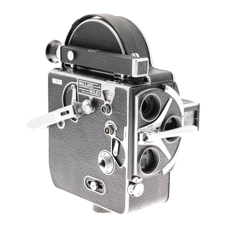
BOLEX H16EBM User manual

ElOL..E>C
IN. T ERN A T ION A L
S.
A.
CH-1450 STE - CROIX / SUISSE
SERVICE APRES-VENTE BOLEX
AFTER-SALES SERVICE
KUNO·ENOIENST
PIECES DE RECHANGE ET INSTRUCTIONS TECHNIQUES
ERSATZTEILE UNO TECHNISCHE ANLEITUNGEN
SPARE PARTS AND SERVICE INSTRUCTIONS
CAMERAS
KAMERAS
H16EBM 300401~
CAMERAS
EDITION
1971

INTRODUCTION Keeping the catalog up- to-date
-
,...,
BOL-EX.
You are requested to file in this service manual all the correspon-
ding printed matters which you wi 11 receive henceforward and to check
the informa
t
i
on contained therein wh('never you wish to compile a spa-
re parts order.
All technical documen Lnt
i
on is [,upplir"" to your service de pa r tmen
t
on
a loan basis
:Hld
mils ;
by
no rne:lll~;
{w
handed over' to third parties.
BOU~XIN'rERNA'rIONALS, A.
Arter-Sales Service
CH-liILjr)
SI,p-Cr'o.i.x / Swi.bprlnnd
Every document of this car..'l.101 ,110
i
n
compcso.l
0['
numbe
re.l "boxes" respectively
"columns"
con
tni.n
i
ng the following information:
Box No.1: The type of
documcn
t ,
i.e.
Box No.
2
:
Box No.
3
:
Box No.
1
:
Box No.
')
:
Box No.
(,
:
Box No.
1
:
TM index: white paper
IN'l'RODUCTION:
wh
i
te paper
PD
IT
FM
spare parts sheet : whi te paper
technical ins
t
ruc
t
i.ons : salmon-pink paper
modification sheet : blue paper.
~
-
~
,
•
9
i
7
11
'"
•
.~
H3 1
~
01.71
E
.s
cl:
I~
Filing order :
IT are filed after the corresponding spare parts sheets. If there
are several versions of the same subject, additional PD may be is-
sued. If no special IT are elaborated, the technical instructions
belonging to the original PD are also valid for the additional PD.
FM are filed so as to face the corresponding PD or IT, according
to the indication in box
9.
**
The
name
of the sub;jec t treated.
The product to which the treated subject belongs.
The serial number indica ti
ng
the introrluc
t
i
on of the subject trea-
ted. (Approx.)
The trade mark of the manufacturer.
The name of the catalogue (see also label on back of folder).
The issuing date of the document.
Filing order :
- INTRODUCTIONsIJeets : Of all the INTRODUCTIONsheets bearing the
same indications in boxes
L -
(i -
11, only the sheet with the la-
test issuing date must be kept.

~
~
j
•
7
•
•
'"
11
·s.
H3
2
~
01.71
E
.s
ct
Keeping the catalog up-to-date
INTRODUCTION
E30LE:X::
12
"---------------------------------------------------------------------------
- TM, PD and I'r : Of
,'1.11 U]p aho o
t.:
be.i r
i
ng the same
.ind.i
ca-
t
i
onr:
ill
b
o
x
on
I - (, - 10 -
11
(J -
6
for TM), only the sbeet
with the latt~st i::;::;uing date must be kept.
ATTENTION': When d
i
scn rd
i
ng a super-seded sheet, be sure that
the
c or-renpond
ing FM are
o
lim
i
na te d :It the same time
- F'M : Of
J
ll
l,h(~
F'j'Ij
be.iri ng
the same indications in boxes
1 -
6 - 9 - 11,
only the sheet with LtJe latest issuing date must
be kepI..
Box No.8: The 1:uw;uag0 in which the documen
I;
iu printed :
*
trilingual
F
D
E
French
Germlln
Enp;ii.f1Ii,
Box No.9: Space I'P '>erved
I'o
r
Spf'C
i
a I indica tions.
Box No.
10 :
On the FM,
tb
i
s space con
ta
ins the speci fica tions in box
1 -
10 - 11 - 7
of the PD or IT for which the FM is valid.
Letter of tab under which the PD and IT are filed.
Box No.
11 :
On the IT this section is devided into two parts, the lower
showing the page number of the PD whereafter the IT are filed.
The page number.
Filing order :
- TM, INTRODUCTIONsheets, PD and FM : Arabic numerals in nume-
rical order.
- IT : Roman numerals in numerical order.
Box No. 12 : - On INTRODUCTIONsheets : miscellaneous
- On PD : "exploded view" drawings with part numbers
- On IT : text.
Box No.
13
:
Sketches illustrating the technical instructions.
Column No.
15
:
The number of the respective modification.
Column No.
16
:
The old parts, valid before the in troduc tion of the modifica-
tion.
Column No.
n
:
The new parts, valid after the introduction of the modifica-
tion.
Column No.
18
:
Explanatory notes.
**)
On receipt of a FM, you should rec
t.i
I'y
Lrnmediu Le
Ly
the corresponding docu-
ment.

Conventional signs
INTRODUCTION
SOL-EX.
Sign
Signification
As a rule, compound
rl.~J
r
t.~
wh
i
ch have only one or
no svmb oI
"t
,,11. cunno \: bR d ism.m
t
l nd .
Their
componnn tr. are , conr.eq uontly , uo l. available sepa-
rately.
Design ava
i
Lab Le .
( )
Part not available.
( +:
Superseded design. Available as stock lasts.
Faulty parts. to be returned for exchange. Cheap
parts may
be
des troyed .
Moreover, this sign constrains the repairman to
fi
t
the ne'" version on any apparatus equipped wi th
the old one. no matter for which reason the appara-
tus is submitted to him.
( ) *
Available for fully equipped
service
stations.
Parts appearing in the dotted field are available
as an assembly.
The respective reference is to be found in a corner
of the field .
...xc.=]
Quantity of identical parts going wi th the assembly.
01 1
0=
numbe r
i
ng
of thp.
dp.ni'~llfj
(to
dp[jipnFl~,(>
int,PJ'-
ch.mgeab
i
Li
\:y).
0c:=J
I 2/1 &"3
Part interchangeable.
Design ~ may be fitted instead of
CI>
and (}).
0c:=J
NIl/2
Part not interchangeable.
Design
CI>
cannot be mounted instead of ~.
Design ~ is not interchangeable with
CI>
but
with
G).
0c=:J
NI
2/1;
I
2/3
c:=J
d= •••
e=...
Mechanical characteristics (thickness, diameter,
size, length, appearance, colour, etc ...) enabling
you to distinguish the old version from the new
one.
~
~
,
•
•
i
"
'"
•
sH3
3
"b
01.71
E
.
E
4.
12

Conventional signs
INTRODUCTION
E30L-EX:
-[
]'I'he
bracke ted parts make the
oe,/
version
interchangeable with the former one.
Cd
Z= •••
Numbe r of tee th of
11
gea
r .
Parts to be moun ted
accord
i
ng to need (for
ad
jus tmerrt ) .
_No . Design valid up to serial numbpr.
No __ DRsign vali.d from serial numb"r.
@
I
@
I
(1)
1
@
I
~ I
®
I
(j)
1
Symbol of grease to be applif'd.
Symbol of oil to be applied.
Symbol of glu" to be used.
Symbol of paint to be applied.
Symbol of mastic to be applied.
Symbol of thinner to be applied.
Symbol of solid Lub r
i
cnn
t
to be appl i.ed,
Part shown on another page or in another catalogue.
Part not available.
If shown in a screened area it will be included in
the corresponding assembly.
The above mentioned signs do not belong to the spare parts number and may, therefore,
be omitted when placing an order.
-e
~
'\;
~
i
•
7
•
,
'"
"
sH3
4
1:
01.71
E
1
12

INTRODUCTION
EINFUHRUNG
Signes conventionnels
Gebrauchliche
Zeichen
Conventional signs
E30LE::X:
F) Code de couleurs des fils electriQues et gaines Isolantes.
D) Farbcode fUr elektrische Drilliteund IsolierhUllen.
E) Colour code for electric wires and insulating tubing.
Couleur / Farbe / Colour
Jaune / Gelb / Yellow
Noir / Schwarz / Black
Rouge / Rot / Red
Vert / Grlin / Green
Blanc / Weiss / White
Bleu / Blau / Blue
Orange / Orang~ / Oranl';e
Beige / Beige / Beige
Rose / Rosa / Pink
Violet / Violett / Purple
Brun / Braun / Brown
Gris / Grau / Grey
Non isole
Nicht isoliert
Not insula tp.d
Aluminium (gainage transparent)
Aluminium (durchsichtige Isolation)
Alumi.nium (transparent insulation)
Cuivre (gainage transparent)
Kupfer (durchsichtige Isolation)
Copper (transparent insulation)
F) Afin d'en faciliter la lecture, nous vous recommandons de retracer
sur les plans de cab Lage les fils avec leur couleur correspondante.
D) Wir empfehlen Ihnen, zwecks besserer Lesbarkeit die Drahte auf den
Verdrahtungsschema mit den entsprechenden Farben nachzuziehen.
E) For better intelligibility it is recommended to trace the wires on
the wiring diagrams with their respective colours.
*
5
I~""""....
r---------~--------•.r-----------------------------------------~,,,"""~,',
·5
'i
1
®
®
CD
@
o
CD
@
®
GD
®
CD
@
®
H3
01.71

)
Table des
rnatieres 2
s·
TM
Inhaltsverz eichnis
E:JC>LE::X:
Index
1~
A
Porte-objectit Objektivhalter Lens Holder
8
Viseur reflexe Reflex Sucher Reflex Viewfinder
C
80itier ~ gal'nage Kameragehause -Bele derung Camera body-Leathering
0
Couvercle-galnage Deckel- Belederung Li d- Leathering
Manivelle Autzugskurbel Rewinding handel
EPlatine superieure Obere Werkplatte Upper base plate
F
Griffe -volet presseur Greifer-F'ilmandruckplatte Claw-Pressure pad
Obturateur Sektorenblende Rotary shutter
G
Mec.anisme-m cteur Mechanismus- Motor Mechanism - Motor
H
Circuits electroniques Elektronische Schaltungen - Electronic circuits
J
Poignee Handgriff Grip
K
Schema elect rique Elektrisches-Schema Electric diagram
L
Plan de c.ablage Verdrahtungsschema Wiring diagram
M
Accessoi res 2ubehor Accessories
N
Cotes Masse Dimensions
.;-;
7
8
9
I
1
H
J
06.71
*
1
-s
J
EBM
-,
)
-------- --- -----

PO
Porte- objectif
Objektivhalter
Lens Holder
H16EBM
SOLE=><
~~------------------~
.;.::::::::::::;:;:::::;:::::::::;:::::::~:i};~:~..;;:;:;
:.:
::.::.
"::;:
.:::::
::{
.:.:.'
.:;:;:
r:=::-::c::c:-:-1::':"
,)-==-==.J ::::;~
)
300 401
-=-C:>
~XlllO.40.31 KPI
)
,::r
2X 1183.22.131
NNI
:,:,::Be
2907
Ax1
(N)
e=O,
30
Bx1 e=O,32
Cx1 e=O,34
Dx1 e=O,36
:.:.'_~;=;=====E~X=l~'"
:::~:::
::~;~::
:~:1:~:
:,=;::=--:;-:;7,;::-;;"\
;::;::L-----"'''--IA
)
.
I
~
IllO. 20.
131
KPI
i\
::.'
BCM
2514 M2
06.71
*
A

H 16 SB{SBM
mounting proceedings of the lens
583
--------------------'

. ':;. ~,. . . (.( i'
Holder
SBM
State of the lens holder as per fig. 5 with gate (a), a
shim'plate
(b)
of medium thickri~~~ (for instance e
=
, d,30~m),
a
spacer (~) of medium thickness and the reflex
pris~ (c) mounted.
Preparatio~ as per fic.
6
Fit the lens holder onto supportBJ
811w
ith the 2
~screws and nuts 8J 811
E.
Place 'mirror 8J 1597
oppositi the gate window and retain it with spring
(d). SwItch on the autocolllmalor to position 1 (min.
l,ight Inten~ity). Cent~r the gate window with respect
to theatit6eollimator axis. Siide the autocollimator
,.enst~'about·25 em from' the'lens,holder, adjusting
the Yerhier scale
to O.
Horizontal ad iust~ent:Adjust the angular position'
of support 'BJ811 so' that the
I
urninous
I
in~ appears
'diamyJricallyin the eyepiece} fig. 7.1, position
A.
':V~~t~cal jdju~tmenl : Loosen screw (f) and'turn screw
"" (e) )Hh~ vieW to bringing the lens
ho
lder
into
its
~'erfj'~al
'pI
ane
• \". "~:;: ." 0"",' 0'
'Z,}P'aralle1ad"iustlllent of the prism
p~ttp
ther·eflex prism
and
remove mirr~r' 8J1597 •
toose'o si;r~w
(h) and .set
the-prism parallel with "
resp~et' toth~ gate by
ad
i ngon screw
In"
and on' "the
2·scre~s·(J).)he 'riosition
~f
the peism, is corr~et '
once the luminous') ine is visible
in
the eyepiece as
~~r pos jtjon-~,butpositions 8 arid c,fig• 7.2, are
'slin 'acceptable.' ,
adjustments precede the adjustment of the flang~
focal dist~nCeand may
be
rectified while adjusting
'the flange
fecal
djstanc'e.,
of
Hie ground glass screen
, ofth~pri~m.' , ,
2·
H 16 SB
300'001
W
I'
a
J--------"~
Fig.
5
\"
Fig. 7.1

H
16 SB
SBM
~~r
SOLE~
300 '001
flange fot~j Histance
hep~ratiori as per
.f
i
q,
8.
F
i(the cali brat i on
'I
ens
BJ
151 and the bayonet support
SJ1310
to the lens holder. Switch on the autocollimator
"fo position1(min.light intensity). Slide the auto-
ccll
imator tube so that the
I
ine seen
i
n
the eyepiece
hasthemaximilrii of contrast, i 1iustration D. Note the
difference with respect to the zero of the vernier.
Thts
figure, read in mmon the vernier , indicates the
\ value in 0.01 mmby which the thickness of the shims
,previously used inu'stbe varied, 'so as toobtain the
following readings
on
the ~ernierscale:
ro:;2'
divlsions
I
=
+
0.02
mm
----::--=--_,
---------I ,-
2.4
Adj~~tingihe flancie focal distance
bf
the qround glass
"pr,ism
~Removemjrror
BJ15,97
and switch
on
the
autoco
l l imator
topoiition2 (max.1 ight intensity).
'Acti
n
~everse order on screw (j) and on screws
(1)
so
asf
o maintain the oaral le l isn
of
the prfsm and to bring
,thef)arigefocaldi~hnc,e of the ground glass to
"<t-,·_· -,,"~
,,<'
I
+2dfv.isibns
I
=
;,: :..
0.02
mm
of the read rig noted under paragraph
2.3.
,",' Screws
-p )
eto
be screeed and (jib
1ocked
through
'tightenjngof scr,ew (h).
Z8Hamihd" "
,'~Pre~'il;~U~n
as
per ,fi
g.9
,li gh~ source at (m).
Fhcl.Isthe magriifyi ng glass
BJ
810 0[1 the edge? of the
?p~ismaperture. ,"', ,,' '", '
c§~ter th~white rectangie in the red,one.
Tq,c.arry ouLthe horlzontal adiustmenr, slightly loosen
s~relVSJnland act with the eccentri c screwdriver
'BJ1594
i
n
(0) •
To~ufthe vert i ca
I
ad
i
ustment, s light
I
y loosen
an{a'ct
with
~J
1~911,in
(r ),
Afterwards
af)d.(p). ,
parali e
I
defed appear between the 2
ightly loos~n sc~iw (s) ~nd al1gn the
aask )
u. , ,
ih~.Hslideinthe film guide,but
pressure exerted byspr
i
nq leaf (u)
,>,.' ',-, ,"' .',
.,
BJ151(F25)
BJ
(.',
\ \--,'BJ
1310
\\
-\~BJ
811E
- BJ
811
Fig. 8
BJ
810'-, -'"
BJ
1310 --" '"
\
1-

..;
-;
(a) on the lens
.'0.
all ov
a
sl ightplayin
by
frame in· posi
Lon
on.P~-the
shutt~r.m~st
-- ,
- , .
.
---
,-:.
-
_
.

H16EBM
300 401
==C=>
Viseur reflexe
Reflex- Sucher
Reflex - Viewfinder
PO
~./~ ••_.I~.r••
':.<.' '-.
~1710916
c~,
.~>. . -'- __~ /. ~~
_f----------.4XI13:-20-160xl
BCE2699 K
....
.....
~-
.
I •••• .."
,
)
'" '
..
·
·
·
·
,
·
•••••• I
......•
.....•
".
...
~/-----:--2XlllO.35.161 NIl
:' l
3XILC10271
,
)
....····l ,
~,tt--...-,. :
(~;~~£~~)~i)
LCE1024 A
~---------5X~~
,;
~
~
.~
'"
-e
')
1i
,
~
~
H
3
06.71
*
.S
]
EBM
·s
<t
-/
2xILC 10141
B

:).,
View:find~r
.
,
While adjusting the reflex viewfihder onto the camera
hous
i
nq , pin (b)miJst engage in the slot (a) of the
. eyepiece. Introduce the beak of screw (c) in the
he)icoidal slot of fhe eyepiece (a) and screw without
,tightening. .
Ceoter the ~askinside eyepiece
(a)
with tool
BJ 1043.
Al ign front prism
(d)
(fig.
2)
by acting on the
3
sc~ew~
(c) until the' image reflectsd
by
the prism
coincides with the mask of the eyepiece, still by
maintaining a dist~nce of 9mm.
Mount the lid.
1.2
Adjustinq
tn~
eyepiece (fig.
1)
Equip the
Camera with a standard lens and project a
beamoi' parallel
I
ight 'rays through the lens (e.g. via
aprojedo'rLSight'the eyepiece with a dioptric tube
8Ji016
which ~~st be adequately aligned and set to
infi~ity: Subsequent
I
yturn ad just i ng ri ng
(h)
unt
i
I
.the
graln
of
'lohe ground glass screen appears perfectly
sharp.
Turnlh~'graduat~d collar (g) until· the line +1
ccii~c'ides with the mark of adjusting ring (h).
"Ti~h ~n sctews' (j).
\
I
1-------------------
H 16
251'501
Fig •. 1

)
PO
Boitier
Karnerapehause
Camera
body
H16EBM
)
300401
==C>
ta
.c-
?::~-------
~;I~;::::~~..
)
I
.,;
~
~
~
'"
-e
)
.,;
~
j
'"
·s
1:
~
<l:
4X~f---~
HJ
EBM 06 71
*
1Ib.~\F)
Gainages
~ (D) Belederung
(E) Leathering c

")
300 401
-===C>
H16EBM
Couvercle - Manivelle
Deckel -Aufzugskurbel
Lid -Rewinding handle
PO
(.;~; ::;:;:; •.:::.;;:;;~:~::.~:~:~:~:~:~:~.;:~:::~:~:~:~:~:~:::~:~:~: ~:~{:~:~:~::::::::::::::::::::. .:.::::::::::~:~:~.::~:~:::::::::::::::::::::~:~;::::::::::::::':':':':' :.:.:.:.;.:. ;':';':';':;.;.;.;.;.;:;.::;:; .• ::;;":::::::":::::::;:;:;:::::::::::; ::: ;:;:;: .•~:{;~:~:::::::~: ':;. ;:;:;:;:;:;:::;:;:::;:;:; :;:; ::: ::"::~::;;;:::~:;:~:;:~{:}~:~:~::::::; ',' ••••• ,;.,,;.;.:.:.:.;.,.;:;.:. :::;:::::::::=: .:::.:.:.: •••••:.•••••••,',', .~.:.:.:
.:.;.:.:.:.:.:.:-:.:.:.:.:.;.:.;.:.;.;.;.::;::.::::::::::;:;:;1 ti
:::::::
)
c....
'.:.;.
~:t
)
BeE
1130xl
~
E
.:
~
~
)
,;
./
~H3
~
06.71
*
e-{(F)
Gainages
0
1
(D)
Belederung
.~
(E)
Leathe ring
~EBM
:s
Q:

PO Platine superieure
Obere Werkplatte
Upper base plate
H16EBM
E30LE:X:
300401
===Co>
2XI312'82'121~
2X 339.87 .1001
2X IBCM2358~ '. ' .
\j ..'
.. __ I
BeE 1186 P
3
X
I129.35.1OO1OX~.,. __ •••
'>. =:o--.L:~="--'=.J
2xI3
6
2.5o.nl
)
,
,
"
.,;
~
~
~
)
,;
~
t
j
'S
'l:
~
Q:
,
IBeM21961,,' • ~, '-:::' •
2X~~:"""
2xI150.26.16 ox~'
H3
EBM
06.71
*
E

1.1
Sprockets(fig.n -
" Place sprockets (a) in raised position by means of ,
tool BJ 1503
and
s
l ightly tighten one screw
(b)
in
vie.lv-of the adjustment of the automatic loading.
Loop'formers' (fig. 1)
loosen the 2 screws 1dJ
ahd
bring lever (c) in open
, position of
the 1
oop formers. ,
'Position and let the lower loop former
(e)
rest
. aqainst'the film gate and place the up~er loop former
(g) afshortdistance of the
incl
ined plane of the
film gak T\ghten
sc"r~ws
(d).
1.3
Automa*ic loadinq (fig.
2)
Pr~p?ration'as Qer fi g.2, camera mounted.
,Dis,~ng6get~e motor clutch, set the
lateral
release
buHon,
.d.h
M.
Operate the mechan1.sm with the hand crank •
Gad on?
length of film previously cut with the
bui
1
t-
in cutter ,
• > -
>
The fi
I
In
must be
.qu
ided by the loop former into a
Iud'i na
I
.pos
ili on, so
that
th~ claw e;s i ly enters
'f
il m ,~djust if necessary by nod i fy i ng
~ion of the'up~er sprocket.
the lower loop former, the film must
enq.aqe'.Tree
y
with
the sprocket teeth without dis-
'sprocket
gUidEr.
Ad
just if necessary by
, 'pas it ion of the lower sprocket.
,c:,·,Cal~ry,.o1tt-several oadings at aspeed of18f./s. "
thec~m~rp freely without
H 16 RX4 - M4
I-------~, SOL-EX
..'
.
~;':"
--.,:-'t
251 '501
...•
'
Fig. 1

..,
}
300401
==C>
Griffe Valet presseur
Greifer Filmandruckplatte
Claw Pressure pad
H16EBM
PO
)
(N) e~0.4
e:0.6
e:0.5
IBe
2488xl MIJ
BeM
2491 Hxl a:21.5
.Ix1 a~21.4
Kxl
a:21 , 3
Lxi a:21. 2
Mxl a:21 , 1
Nxl a=21
'-- __ --"T'---'. a=20.9
-----;-.--~Be
27911
"';".;'.;";';".;',;"~~~~"""'"'''' ••••• J
.
';':':':':'::: ::::::::::-:.:.:-:.:.:.:.:
".
~-----JiiC11~
r~~~
r.:o;;:;--:c::-:-~-'.C..-,
BC
1196xl
1362.32.11 ,
)
1
BCD
655x1
2X
11<'9.2;;.1002 ,OX
06.71
*F

H 16
Claw ,,-Pressure Pad
SOLE:><
251 '501
->
1.1
Adiustinq the framina (fig.
1)
Inaert the test pressure pad BJ
1514x1
in place of the
norma 1 pad.
Load th? camera with a length o~ test film.
Light up the taking aperture from the
outs
ide ,
Seen fr~m the inside, the edges of the aperture must
lie at equal distance from the middle of the
perforation when the claw retracts.
In case of need, select the corrett cl~. in order to
achieve the adjustme~t.
1.2
Friction torgue of the claws on the film (fig.
2)
While refitting the claw assembly onto the eccentric
axJe,adjust the friction tbrque oh the film by means
of the spring washers and run'in the ~ssembly by
ope~ating the cam~ra for about
10
times of the spring
notor
capac ity.
prace the claw assembly on platform
H15
of tool
13J
1572 M1.
Rotjte)he disk in,the direction of the red or white
arrqw ,'dependi ng on whi
ch
of the forward or backward
motion ~I~w js checked, on which occasion these must
rest against the feeler of the dynaeone+er ,
The friction io~que shown by the dynamometer must be
of
111 ::.
2
g
I'
~ for:f~e,for.ard motibn cla~, and
1
7::.1
gl
~forthe backward motion one.
this ~hecking may also be carried out when the camera
i~ mounted. For this purpose, rem6vb the tlaw
protection.
Diiengage the mechahism so as to operate the camera
,IIiYth thaharidcrank for reverse motion.
Place toolBJ
1572 M1
onto the camera as per fig.
3,
so that the fee
1
er of the dynamometer
1
ies
,~ 6pp~sitg the lorward mot'ion claw (a)
~ opp6sjt~
ihe
backw~rd motion claw
(b)~
Thl; c~ecklng may be effected by simply rotating the
dynainometer, so
that
the claw moves free
I
y in front
of
the ti
1m'
gate.
1 '
/
/
BJ 1572 M1
~----------------------------------------
,
'
.~----.--'.'
-~---'--
.
..
,.
.
---"-
Other BOLEX Digital Camera manuals
Popular Digital Camera manuals by other brands
Schäfter+Kirchhoff
Schäfter+Kirchhoff SK8160GKO-4LB instruction manual
Sony
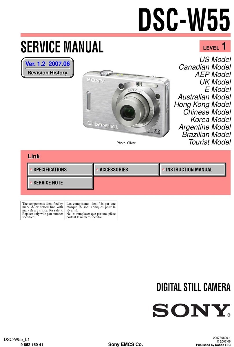
Sony CYBER-SHOT DSC-W55 Service manual
Olympus
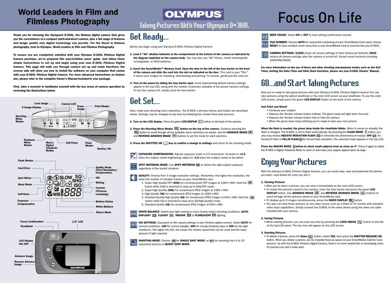
Olympus D-360L - 1.2MP Digital Camera quick start guide

Olympus
Olympus E420 - Evolt 10MP Digital SLR Camera instruction manual
SVP
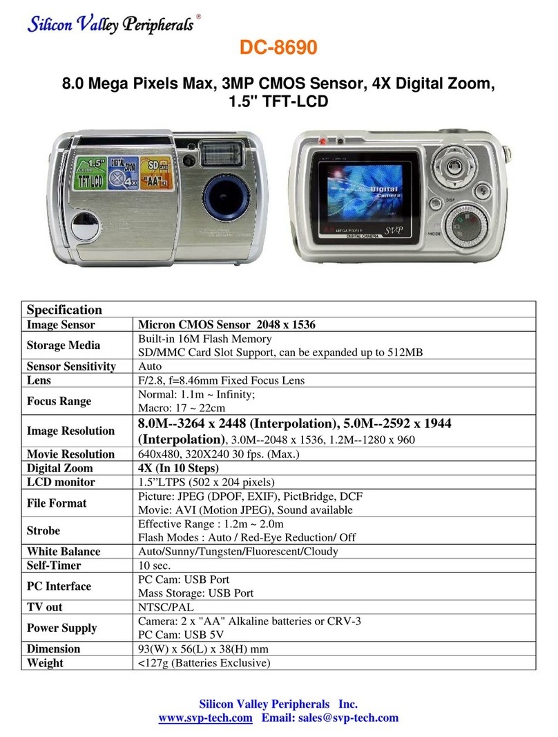
SVP DC-8690 Specifications

FujiFilm
FujiFilm X-T200 New features guide
