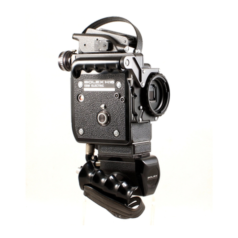
BOLEX H16 REFLEX User manual

H 18
Reflex,
1

We strongly recommend that a test
roll of film is exposed in the camera
when first purchased. This will help
you to get to know it and will ensure
that the instructions given in this
manual have been carried out cor-
rectly.
The camera is supplied with:
1 auxiliary multifocal viewfinder
1 filter holder on the camera
1 set of five filter holders
4 gelatine filters
1 rewind crank
1 folding rubber eyepiece
2 turret plugs
1 empty spool (100 ft.)
Accelerated motion 16
Accessories 44
Additional lenses 9
Animation. 37
Audible signal 30
Auxiliary viewfinder 9
Cable releases 45
Carryi ng case. 47
Cartoons 38
Closing the viewfinder 9Hand cr
Cold 43
Control lever for instantaneous or time Heat
exposures 17 Humidity
Control lever for loop formers 27 Lens cap
Control lever for variable shutter 20 Lenses
Lens sea
Depth-of-field 12 Lid.
Diaphragm. 13 Lighting
Disengaging motor. 19 Lightmot
Distances 12 Loading
Double exposures 23 Locking
Editing films 36 Loop forr
Exposure table . 13 Macro-
Extension tubes. 45 Mainten
Motor di
Fades. 21 Motor re
Faults (on film) 40 Motors
Field adapter 9
Film knife 27 Optical a
Film leaders 7
Film plane. 12 Pan-Cin
Film retaining arm 5Panning
Films. 7Parallax
Film sensitivities. 13 finder.

-321 sound projector.
This projector is
ed with the same high precision as your
It makes the perfect partner for the H 16 Reflex
s full justice to your sound and silent films.
ore, it ensures complete film protection and
recording of sound on films with magnetic
cy range:
c sound: 50 to 10,000 cycles/sec.
±
3 decibels
ound: 50 to 7,000 cycles/sec.
±
3 decibels
-311 sound projector.
Has the same features
-321, but is designed uniquely for projecting
ound films.
er:
cy range: 30 to 16,000 cycles/sec. ±3 decibels
utput: 15 W
eaker:
o the projector lid, power output: 6 W
(available as accessory), power output: 20 W
, lens:
lengths available: 35 mm f/1.3 - 50 mm f/1.3
m f/1.6
Throughout the world, Bolex cameras have acquired
a reputation for unrivalled quality. The H 16 Reflex is
the most advanced and comprehensive model in the
Bolex range. It is appreciated not only by discerning
amateurs and explorers but also by many professionals,
scientists and those in the fields of industry and edu-
cation. Its robust construction ensures excellent per-
formance under all conditions.
With a world-wide network of agents, Bolex offers
impeccable after-sales service in practically every part
of the world. If service is required, return your camera
to the Bolex distributor in the country concerned.
He is authorized to carry out repairs, adjustments
and maintenance work. By so doing, you will benefit
from the guarantee. In any correspondence, please
remember to quote the serial number engraved on the
base of your camera.

camera is strong, very easily adjusted and
fitted up.
The Bolex swivel-joint complements the tri
enabling rapid camera levelling, a great ad
when filming on uneven ground.
Underwater housing.
Enablesthe diver to fili
to a depth of 300 ft. Absolutely watertight
stable and very simple to handle under wa
camera is quickly removed and fitted into the
without tools.
I
Bolex super titler.
A high-precision ins1
light yet robust, enabling you to produce
variety of titles, as well as special and trick
with excellent results.
Carrying cases.
Several models available
quality leather and in aluminium.
In preparation.
A special electric motor is no
designed for single frame filming, for use with
I
out an automatic timing device.

ontents
Get to know your camera
7 16 mm films
8 The reflex viewfinder
9 The auxiliary multifocal viewfinder
11 Optical equipment
11 The turret
11 The lenses
12 Distance setting
13 Diaphragm adjustment
14 The filters
Camera operation
16 Winding
16 Filming speeds
17 The releaseselector
18 Electric motor drive
19 Hand cranking
20 The variable shutter
21 Lap dissolves
23 Double exposures
Camera loading
27 lnsertinq the film
29 The footage counter
29 The frame counter
30 The udible signal
Unloading the camera
31 When the film is fully exposed
32 When the film is only partly exposed
Practical advice
33 Camerastability
34 Film composition
35 Panning shots
35 Lighting
36 Editing and titling films
36 Adding sound to films
37 Animation technique
38 Cartoons
39 Macro- and microcinematography
40 Faulty films and their causes
42 How to look after your camera
44 To complete your equipment

Get to know your camera
1234567
15 14
4
1 Reflex viewfinder (page 8)
2 Footage counter (page 29)
3 Lever for disengaging spring motor (page 16)
4 Spring motor winding handle-spring run: 28 sec.
at 24 f.p.s. (page 16)
5 Reflex viewfinder closing lever (page 9)
6 Frame counter (page 29)
7 Coupling spindle for electric motor MCE 17 Band
film rewind handle (pages 18 and 19)
8 Variable shutter dial and control lever (page 20)
9 Film plane guide mark
10 Coupling spindle for electric motor MST (page 18)
11 Exposure control knob for instantaneous (I) or
time exposures (T)
(single frame filming) (page 17)
12 Film speed selection knob (page 16)
13 Front release for normal running (page 17)
14 Side release for normal running, continuous film-
ing (M) and single frame exposures (P). Can be
operated by cable (page 17)
15 Threaded holes for various accessories and motors
Electric motors.
See page 18.
Extension tubes.
Used in macrocinematog
achieve magnification of minute subjects,
insects, filmed at very short range. The reflex
system of the H 16 Reflex camera permit
accurate framing and distance setting. The t
supplied with a calculator table.
REX-Fader.
Automatically and smoothly op
closes the variable shutter, thus permitting pro
quality fades and lap dissolves.
Automatic
self timer.
This accessory ena
operator to get into the picture himself by sta
camera running six seconds after the timing me
has been set and allowing for a predetermined
time of between 5 and 20 seconds.
Cable releases.
Recommended for normal c
frame filming when absolute steadiness is r
Two lengths available: 21 and 40 .
Bolex lightmeter.
It is always advisable tc
exposure meter, particularly when filming in
The Bolex lightmeter is designed for motion
and especially calibrated for use with the H 1
camera.

16 Leverfor suppressing audible signal (page 30)
17 Upper spool shaft for feed spool
18 Upper loop former
19 Upper sprocket
20 Pressurepad locking pin (page 27)
21 Loop former locking lever and opening knob
(page 28)
22 Pressurepad (page 27)
23 Lower sprocket
24 Lower loop former
25 Lower spool shaft for take-up spool
26 Film knife
27 Spool ejector (page 31)
28 Retaining arm
29 Feetsetting on footage counter (page 29)
201918
16 .
5
17
27 2829

6
30
I
31
30. Turret lever (page 11)
31 Threaded hole for turret locking screw
32 Front release for normal running (page 17)
33 Filter holder (page 14)
34 Turret locking clamp (page 11)
35 Shoe for attaching exposure meter (page 13)
36 Auxiliary multifocal viewfinder (page 9)
37 Lid opening ring
38 Three threaded holes (2-
3/8
dia and 1-'
/4
dia)
for tripod or hand grip
39 Serial number of the camera (page 1)
Special care of the camera in tropical reg
be taken to protect both camera and film agains
Airtight boxes are available to store films in th
camera longer than the time necessary to expos
The camera and all accessories should be cI
Leather and the carrying cases should be treated
leather merchants.
To prevent hot, moist air from condensing and
growths, do not place your equipment in its c
freely exposed to the air.
However, for storing your equipment, especially
airtight tin boxes with a silica gel or calcium c
using these chemicals too liberally, however, t
might damage leather and film. A relative humi
Care should be taken to prevent any of the ch
your equipment.
Precautions against cold and sand.
If you
or in very cold climates, send your camera
greasing and winterizing.
Guard against getting sand or dust in your camer
its mechanism. Where necessary, put the came
and, for extra protection, put the case in a plasti

16 mm films
. The H 16 Reflex camera takes 100 or 50 ft. spools of
single or double perforated 16 mm film. Films with a
single row of perforations are used when a magnetic
track is to be added to the original film.
At each extremity of the film there is a leader-approx-
imately 6 ft. at the beginning and 3 ft. at the end-to
prevent the sensitive film being exposed to light dur-
ing loading or unloading. These leaders are usually
removed by the processing laboratories.
Film running times at the following filming speeds
Black-and-white and colour films come in various
sensitivities, which are expressed in ASA or DIN
degrees and indicated on the instructions leaflet
accompanying each film. The date before which the
film should be exposed is normally stamped on the
film pack. 16 mm film is available in the unprocessed
condition with a magnetic stripe for sound recording.
We would advise you against using this film: the mag-
netic layer can cause premature wear on the parts
which come into contact with it, particularly the pres-
sure pad, and metal particles may find their way into
the camera mechanism.
f.p.s. 12 18 24 32 48 64
~
1 rn (, 3 ft) 10.9 sec. 7.3 sec. 5.5 sec. 4.1 sec. 2.7 sec. 2 sec.
15m(,,-, 50 ft) 2 min. 44 sec. 1 min. 49 sec. 1 min. 22 sec. 1 min. 1 sec. 41 sec. 30 sec.
I
30 m (,-,100ft) 5 min. 28 sec. 3 min. 38 sec. 2 min. 44 sec. 2 min. 3 sec. 1 min. 22 sec. 1 min. 1 sec.
7

The reflex viewfinder
The optical system of the H 16 Reflex camera allows
for through-the-Iens viewing during filming as well as
when the camera is not running. The picture formed
ori the ground glass of the. reflex prism is absolutely
free from flicker.
The reflex viewfinder enables framing and accurate
8
focusing of the subject to be achieved. In addition, it
enables you to estimate the depth-of-field, to deter-
mine the correct focal length, to check on the filter
being used and to evaluate the illumination of the
scene.
The reflex prism deflects, into the viewfinder, an
average of 20-25
%
of the light passing through the
lens. This factor has been taken into account in the
table of exposure times on page 13.
Adjusting the viewfinder eyepiece to the opera-
tor's eyesight.
This adjustment adapts the viewfinder
to the operator's eyesight. whether or not he wears
spectacles, and remains the same for all lenses used
on the camera. It is advisable to check this adjustment
from time to time.
1. Turn the turret to expose the reflex prism.
2. View a well-lighted subject.
3. Loosenthe milled ring (b) and turn lever (c) until the
grain of the ground
glass is perfectly
sharp. Then tighten
the ring (b) which
acts as a lock-nut.
If your eyesight is nor-
mal, the line engraved
on the lever (c) will be
opposite the longest
line on the fixed ring.

Closing the viewfinder.
If the reflex viewfinder is not used during filming,
close it by moving the small lever (a) into a vertical position. If
.it
is left open,
there is a risk of sunlight or artificial light from behind the camera entering the
viewfinder eyepiece and fogging the film.
Focusing.
Open the diaphragm wide, then turn the distance setting ring until
the picture is in sharp focus on the ground glass. Then close the diaphragm to
the correct setting.
The auxiliary multifocal viewfinder
The H 16 Reflex camera is equipped with a detachable multifocal viewfinder,
provided with parallax correction from 20" to infinity. Its field can be instantly
and continuously adapted for lenses with focal lengths of 16, 25, 35, 50, 63,
75, 100 or 150 mm. The viewfinder also incorporates an extra lens, mounted on
a sliding bracket. Quickly put into place, this lens immediately adapts the view-
finder to the field of a wide-angle lens (10 mm). When this lens is in use, the
multifocal viewfinder should be set for the shortest focal length (16 mm).
The auxiliary viewfinder can be mounted or removed from the camera in seconds
by means of a lever. It is extremely useful for previewing the subject, and there-
fore picture composition and focal length can be determined without having to
move the camera.
.
-
-
...........
~.
. _1
9

10
Adjustment of the viewfinder field.
The viewfinder field is adjusted by
rotating the disc (a). The focal lengths are visible in the upper window and
also appear in luminous figures in the viewfinder itself, thus permitting a perma-
nent check on the focal length in use.The indicators in the finder window facilitate
horizontal and vertical centering of the subject.
Parallax correction.
The viewfinder is so positioned on the camera as to
eliminate any vertical parallax. To correct lateral parallax, turn the scaled knob (b)
until the number corresponding to the filming distance faces the guide mark.
This distance is calculated from the film plane. Set the sign
00
opposite the guide
mark at the end of filming. To accurately frame subjects at less than 1
Y,
ft.,
the
reflex viewfinder should be used.
Adjusting the viewfinder to the operator's sight.
Corrective lenses of
different dioptric power are available, on request, to adapt the viewfinder to the
eyesight of spectacle wearers. The Bolex distributor for your country will fit
a corrective lens to the viewfinder if you let him know the lens power required.
- - - --- --=---

Optical equipment
The turret.
Simply by turning the turret, you can change rapidly from one focal
length to another, from a medium long view to a long view or a close-up. To
turn the turret, use its fold-away lever. In this way, there is no risk of accidentally
moving the diaphragm and focusing rings. Three click stops ensure that the
lenses are correctly positioned in front of the filming aperture. When using heavy
lenses, such as zooms or telephotos with very long focal lengths, the turret
should be locked (Pos. 2) with a special clamp.
Correct position of the lenses on the turret.
Keep the
lenses positioned as shown opposite, so that there is a
reasonable distance between the wide-angle lens (1) and the
long focal length lens (3). It is as well to remove 100 and
150 mm lenses from the turret before using a shorter focal
length lens, in order to keep its field clear. When using a
heavy lens, such as a zoom, the turret should be locked with
a plug.
~
.'
30
o
The lenses.
The H 16 Reflexcamera takes "C" mount lenses (seeimportant note
below) which have the following characteristics:
Thread diameter: 25.4 mm (1")
Maximum thread length: 4.06 mm (.160")
Film plane / lens seat distance: 17.52 mm (.690")
Lensesshould be held by their rear rings (a) when being screwed into the turret.
Standard lenses
(25 and 26 mm) are suitable for most shots.
Wide-angle lenses
(10 and 16 mm) are used for general views or when it is
difficult to move back from the subject (buildings, interiors, etc.). They give
heightened perspective. 11

Telephoto lenses
(50-150 mm) are used for long
distance shots and are ideal for filming sports scenes,
children, animals, etc.
To protect lensesfrom dust and impurities, it is advisable
to replace the lens caps between takes.
Important. Special 10, 16, 25 and 50 mm lenses
have.been designed exclusively for use on the
H 16 Reflex camera. Lenses with focal lengths
over 50mm can generally be used equally well
on the H 16 Reflex as on cameras without reflex
viewfinder.
12
Focusing
The reflex viewfinder of the H 16 Reflex camera shows you the picture as it
will appear on the film, with its sharp and blurred areas faithfully reproduced.
It is thus simple to focus accurately and, at the same time, to estimate the depth-
of-field.
The depth-of-field
is the area"within which the picture is in focus. It varies
according to the focal length of the lens, the diaphragm opening and the filming
distance. The longer the focal length, the wider the diaphragm opening or the
shorter the filming distance, the shallower the depth-of-field will be. Focusing
must therefore be especially accurate.
Conversely, the shorter the focal length, the smaller the diaphragm opening or
the longer the filming distance, the wider the depth-of-field will be-and the
greater the margin for focusing inaccuracy.
On most lenses, a depth-of-field scale indicates the distances within which the
picture will be in focus. Lenses are also supplied with a' depth-of-field chart.
Distances are calculated from the film plane, marked
¢.

Diaphragm setting
The lens diaphragm controls the amount of light
reaching the film and is adjusted according to the
lighting conditions, the film sensitivity, the filming
speed and the position of the variable shutter. The
amount of light admitted by the diaphragm is doubled
at each successive setting, starting from the highest
fiqure. For instance, moving the diaphragm setting
from
f 11
to
f S
doubles the amount of light passing
through the lens.
The Bolex exposure meter
was designed and cali-
brated especially for the H 16 Reflex camera and
allows for the fact that 20-25
%
of the light is deflected
into the viewfinder by the reflex prism. The exposure
meter fits on to a special shoe (see page 6).
The use of the exposure meter
safeguards against
exposure errors. In the chart opposite, the figures listed
in the column under "adapted exposure times" take
into account the light deflected by the reflex prism.
Exposure times (in fractions of a second)
I
Shutter open
I
Shutter
Yo
closed Shutter
%
closed
I
Filming speed Lever up Lever on
%
Lever on 1
. I
Real Adapted
I
Real Adapted Real Adapted
12 f.p.s. 11/33 1/40 11/45 1/55 /1/75 1/94
16 f.p.s. 1/45 1/55 1/60 1/75 1/100 1/125
18 f.p.s.
I
1/50 1/60
I
1/70 1/87
I
1/HO 1/137
24 f.p.s.
1
1/65 1/80
I
1/90 1/11 2
I
1/1 50 1/188
32 f.p.s.
I
1/90 1/110 11/120 1/150 /1/200 1/225
48 f.p.s. 11/130 1/160 1/180 1/225 1/300 1/375
64 f.p.s. 1/180 1/220
I
1/240 1/300
I
1/400 1/500
Speed
I
Single-frame
I
(selector in position T
I
~~ntrol knob
I
exposure
18-64 f.p.s. 1/30 1/40

----------- ----
,-
Filters
The 1A Skylight filter
for colour films, tones down
excessive blue and improves colour reproduction (in the
shade -or overcast weather, for distant shots, when
filming in snow or at high altitudes). This filter requires
no diaphragm correction.
The 85 Daylight filter
for colour films is a conversion
filter. It is usedfor filming in daylight with Kodachrome II
Type A artificial light film. When setting the diaphragm,
remember that colour film for artificial light, used
with
the 85 Daylight filter, hasthe same sensitivity as a day-
light colour film used without filter.
The Yellow 8 filter
is used for increasing contrast in
black-and-white films.
The H 16 Reflex camera has a filter-slot between the taking lens and the reflex
prism. The filters therefore remain in place whichever lens is being used.
When
filming without a filter, an empty filter holder should be left in the slot
to prevent light infiltration which would fog the film. Seethat the filter
mount is firmly located in the slot.
The set of filters for the H 16 Reflex camera comprises four- filter holders, a filter
cutting frame and four envelopes, each containing one of the following 2" square
gelatine filters.
The effect of a filter varies according to the type of film; its sensitivity and the
lighting conditions. The diaphragm corrections below should be considered as
only approximate.
or
Type Open divide
diaphragm ASA
rating by
Kodak Wratten 1A Skylight
--
Kodak Wratten 85 Daylight
2/3
stop 1.6
Kodak Wratten 8 Yellow 1 stop 2
Kodak Wratten ND 06 Neutral density 2 stops
4
14

The neutral density filter
can be used with both black-and-white and colour
films and in no way affects colour reproduction. As the ASA sensitivity is reduced
four times, the diaphragm can be opened two stops. This filter is used:
1. When the lighting conditions and the film sensitivity require an aperture
lower than the smallest stop on the lens.
2. When it is desired to reduce the depth-of-field in order to achieve special
effects (sharp foreground against blurred background).
Mounting gelatine filters.
Filters are mounted as follows:
1. Hold the filter cutting frame horizontally (g).
2. Insert gelatine filter, with its protective covers, as far as it will go into the
frame.
3. Hold the frame firmly and cut around it with sharp scissors. •
4. Remove the filter by its edges. Fingerprints cannot be removed.
5. Remove the fastening clamp (a) from the filter mount.
6. Open the spring blades (b) and (c).
7. Insert the cut-out-filter (d) between the blades.
8. Press the spring blades (b) and (c) together between thumb and index finger.
9. Replace the fastening clamp (a).
When you have finished, put the filter-mounts in their case to protect them from
dust.
Focusing adjustment.
Placing a filter behind the lens slightly alters the lens
focusing. However, the necessary correction is automatically made when the
reflex viewfinder is used.
Important.
Because of its distance from the film plane, the filter mount cannot
be used as a mask holder for trick effects, such as keyhole and binocular cut-outs.
The shape of the mask will not appear on the film and it will only darken the
scene.
r-
15

Camera operation
ab
16
Winding the motor
Move the side release to STOP and the motor dis-
engaging lever to MOT. Lift the motor winding handle,
which automatically engages with the spindle, and
turn anti-clockwise. Wind the spring motor fully but
without forcing it, then lower the handle and secure
it on catch (a). Otherwise, there is a risk of it turning
with the motor during filming.
Fully wound, the motor drives nearly 18 ft. of film, i.e.
28 seconds' filming time at the speed of 24 f.p.s.
Make a habit of rewinding the motor after each take,
regardlessof how much power isstill in reserve.
Film speeds
The camera has seven filming speeds: 12, 16, 18, 24,
32, 48 and 64 frames per second.
To select the desired speed, turn the control knob (b)
until the corresponding figure is opposite the red dot.
When the film is projected at normal speed (18 or
24 f.p.s.). a lower filming speed will produce an accel-
erated motion effect while a higher filming speed will
give a slow motion effect. When changing film speed,
do not forget to alter the diaphragm setting. When
changing from 24 to 32 f.p.s., the diaphragm should
be opened half a stop, from 24 to 48 f.p.s. by a whole
stop and from 24 to 64 f.p.s. by 1
stops (seepage 13).
-.
~--------------------------------------------------~---------------------------------------=------

Important.
When the camera is not loaded, it should not be run at speeds over
32 f.p.s. as this could damage the mechanism.
The release selector
The H 16 Reflex camera can be used for normal, continuous or single-frame
filming. These different operations are controlled by the
side release.
Normal filming.
This filming method is suitable for most general shots. The
camera runs as long as the operator
depresses-
the front release or pushes the
side release towards M (generally by using a cable).
Cable release.
For maximum stability, when the camera is mounted on atripod,
it is advisable to use a cable releasewhich fixes, by means of an adapter, on to the
side release knob.
Single frame filming.
Push the side releaseto P.
Instantaneous:
turn the knob until the guide mark is in position I.
Time
exposures:
guide mark in position T (for use in poor lighting conditions, such
as indoors).
When making time exposures, open the variable shutter fully or one of its blades
may mask part of the picture.
You can also use an electric motor which ensures absolutely constant exposure
time for every frame at the selected speed. This prevents the slight flicker which
inevitably results from using a spring motor (see page 47).
Single frame filming is used for titles, cartoons, scientific films and various trick
effects, particularly accelerated motion (clouds, sunsets, comic effects, etc.).
Use a cable releaseto prevent any risk of camera movement.
17

18
Continuous filming.
Push the side releaseto M.
The camerawill continue running as long as the motor is wound. To stop the
camera, move the side releas.eback to STOP.
Continuous filming with an electric motor.
Long sequences can be filmed
without interruption by using one of the following electric motors, which are
easily fitted on to the camera.
The MCE 17 B motor
drives the film at the chosen speed, from 12 to 32 f.p.s.,
by the couplinq=spindle (8 frames per revolution), battery driven.
The MST motor
is a constant-speed motor which drives the film, at a specific
rate, by the coupling spindle (1 frame per revolution). For filming with synchro-
nized sound as well as for industrial and scientific work. Various models are
available asfollows:
- 24 f.p.s.: films for commercial use and American TV stations.
Pilot generator, 50 or 60 ~ incorporated; automatic or remote-controlled
clapstick.
- 25 f.p.s.: films for European TV stations. Pilot generator, 50 or 100 ~ incorpo-
rated; automatic or remote-controlled clapstick.
The MST motor is powered by a portable cadmium-nickel battery with an in-
corporated rectifier which can be recharged from the mains, or powered from a
12 V accumulator, such as a car battery.
Other manuals for H16 REFLEX
2
Table of contents
Other BOLEX Film Camera manuals
Popular Film Camera manuals by other brands
Nikon
Nikon D850 Settings guide

Moskinap
Moskinap KINOR-35N Technical specification and operating instruction
Zeiss
Zeiss Ikon Rangefinder instruction manual
Blackmagicdesign
Blackmagicdesign BLACKMAGIC CAMERAS Installation and operation manual
Polaroid
Polaroid NOW user manual
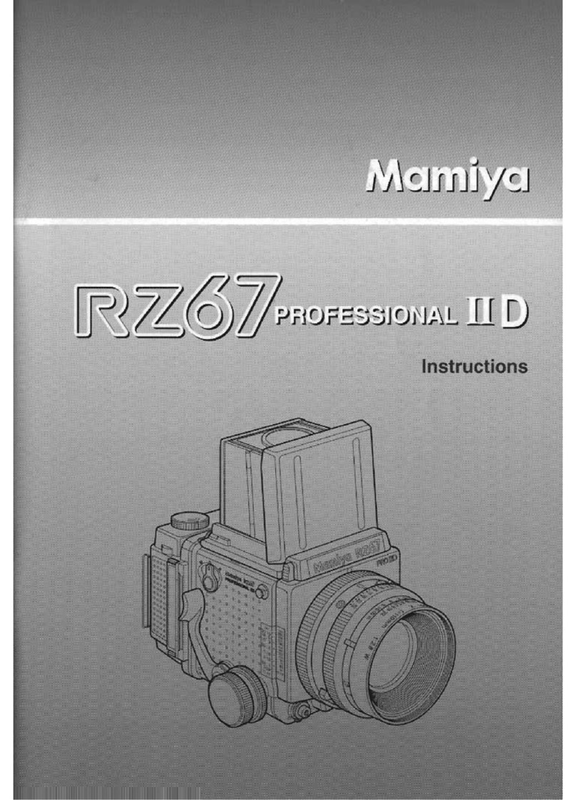
Mamiya
Mamiya RZ67 PROFESSIONAL II D instructions
