BOLEX S-221 User manual

Film-Tech
The information contained in this Adobe Acrobat pdf
file is provided at your own risk and good judgment.
These manuals are designed to facilitate the
exchange of information related to cinema
projection and film handling, with no warranties nor
obligations from the authors, for qualified field
service engineers.
If you are not a qualified technician, please make no
adjustments to anything you may read about in these
Adobe manual downloads.
www.film-tech.com

BOLEX S-Z?LSOUND
PROJECTOR
16mm
Instructions for use
www.cineinfo.co.uk
www.cinephoto.co.uk
I
I
I
I
I
I
I
I
I
I
I,
l,
I
I
r
l.
I
t,
I
I
t,
INSTRUCTIONS I'OR USE PROJECTOR PAII,I,ARD.BOIEX S-22A
]NDEX
D^ ^^^
.ff
2 GETTING TI{E MOSTOUT OF YOLN.
4 SETTINGIJT TIM PROJECTOR
IO IOADING TiiE PROJECTOR
L3 O?ER.ATING
TIIE PROJECTOR
- Projection - Reverse motion - Unloading - Rewinding -
L5 MINORREPAIRS OF PROJECTOR
16 PROJECTIONOI' OPTICAI, SOUN! PRINTS
18 PTJEIICADDRESSSYSTE]VI
- Jse oi microphone - Us*. of record-player or tape recorder -
20 MAGNETICSOUND
PROJECTION
2L MAGMTIC SOiIND
RNCORDING
- Renoriino z mrrqie:l h:cksrorrnd - Reoordinp: snokon nnmmontprtr
vvvavrr
- llhankino fhe ppannA ira Qn..rn m'
,___-*__-o corur-rrg
- DUufIu
maxlng -
ACJESSORY
FOR
THE
SUPERIMPOSITION
OI'SOUND
BOI,NX S-22I
24a
25 MINORREPAIRS OF SOUNDSYSTEM
27 MAINTENtu'{CE
- Lubrication * Cleaning - Replacing projection lamp -
- Replacing other parts -
32 AUXIIIARY f2'I IOUDSPEAIGR
33 I'C-IIDSPEAI(ERJI;-I{CTIONBOX
34 SO}IEHTNTSBY A SOUND
ENGINEER
I. SOLAID
PROJECTION
II. HO}ITO ADD SOUNDTO A FIIM WITH MAGNETIC
TRACK
EQUI?}MNT
The 5-221 projector is supplied with :
- one -Iooo w. tamp (75o w. lamp supplied on request)
- one lens x
- one 2ooo ft reel
* one power cord, ren$trr \3 ft, with J leads
as wefl as with the following accessories which wil1- be fouad inside
the lld of the case :
- one oilcan - one screwdriver - one brush - two spare fuses,
The 3-221 nro'ieetor is fitted with a standarddocus lens of focal
length 5O mn. Two other focal length lenses afe availabJ-e :
- e 35 mm
lensr inteno.ed.
for short projection distancesl
- a 70 mmlens, intended for long projection distances.
PAIIIARD-BOLEX lenses are specially designed to produce pictures
of maximumbrilliance, sharpness and contrast.
The microphone, type D l1-Hi (Coae : SOMIC), which can be supplied on
request with lJ ft of cable, may al.so be stowed away inside the lid.
Use of the special earrying bag (Code : S0H0U), supplied. on request,
is strongly recommended, as this bag effectively protects the lined pro-
ieetor n:sp- Tt nlso has roOm fOr two 2ooo ft reels and thej_r cartOns.
Jvvvvr
- Before using the projector, rmscrew the back panel of the case in order
to remove blocks and cushions from i-nsi-de housing.
II4PORTAN'T

I
I
I
I
I
I
I
I
l_
I
l_
I
HOW
TO GETTIfi MOST
OUTO} YOUR
BOIXXS-22L
- Arransement of Projector and Screen
The distance from the screen depends
on the size of the screen and on the
focal length of the lens used. The
diagram opposite shows the size of the
picture produced on the screen when
using projection lenses of focal length
35, 50 and 70 mm
at various projection
dlstances.
5678
lldtb of acreeh
For example : For a 50 nn lens and a 6 ft
scy.etrn the annrnnriqte nroiention rlistance
rvill1 tre 30 ft.
Set the
beam i-s nrn io oJ-nr nn q
nrn'i onl-ad nrrar
yr vJvv
stand. or table faclng the screen,
the heads of the audience. high enoush so that the
Try to ensllre that the screen i-s al-
ways set squarely in line with the
projector, but if this j-s not possible
the screen should be inclined sli-ghtly
i-n the appropriate d.irectj-on so that
the beam strikes it perpendicularly.
By doing this, picture distortion is
avoided.
2

Fl
>t
c\t
Sc: t i no A
r-rlp.ottot'ta "
Pnn-ion*inn nnnditinnq:ro qnnd if +l^^
r L u!l cu urvfr uvuv
viewins a.nsle is with-Ln :
-^o
,u^ - marT screen
20" - beaded screen.
Tlra min'im,rm cnoonNSflg diStanCe be-
tween the first row of spectators
and the screen may be esbimated by
mrltinlrrins the width of the screen
vy L2.
The distance between the screen and
the row of seats furthest from it
shou-Ldnot be eieater than 6 times
the wid"th of the screen.
0ther Points
In order to obtain good pictur" "oo-
trast, particularly when showing
colour films, it is advisable that
€i r-^ ^L^..f r ^-r-- ttp nroicntod in 3
r afuo orrvuau ullrJ v9 yr uJsu u9u rrr
ful1y darkened room. Flickers falling
on the screen from an open fire in
ncn-t-i nrrt an cl.rnrr'ln he rrl:rded aspi nSt.
r\*!v+vq4urvvb4gf
'l'htr
l'Jolev S-22| nroieelnr wi l'l take
either e 750-wqtt or a 1000-watt
projection Ianp. If the room used for
nroiectinn iq nnmnaratiwelv smnll- a
qvrvur./ vllur:t
750-watt lamp wilt generally give
suff icient ilfumination.
To change the projection lamp, see
page 2J.
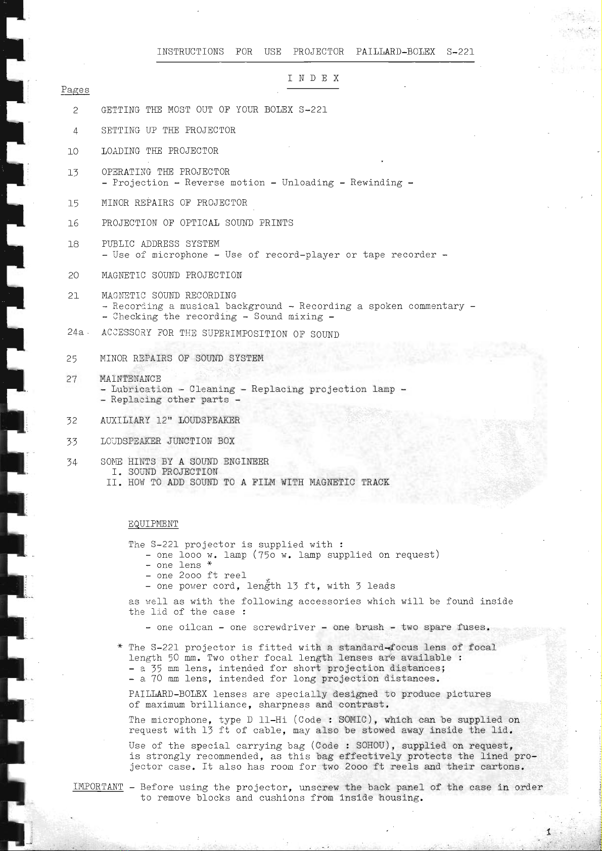
SETTINGUP TIS PROJECTOR
- Openthe case fulfy and lifb the cover off its
hinges.
- Rai-se the upper reel arm.
-'Push down the handle.
- Make sure that the knob at the end of the take-up
spindle is fully pushed in. Then fit the empty reel
on the take-up spindJ e until it is behind the bafl
spring. Pu1l the knob toward.s you in order to fock
the balf spring and to prevenb the reef from fllfing
nf f drrri no lho nrn io n l-i nn
Notice : Reels with standard hub
/ofl f* ra^r -inimum diameter
Tvv r
800 ft reel,
2000 ft reel,
Tmnnrtqnl - Tho
the developing
reels. Reverse
ra'.'i nd'i n -\
f v yY
4fru !116 / .
lt n
n
- Insert the lens into the lens-holder.
tr'or Sound Pro.iection with built-in T,oudspeaker
- Remove the cable winder from the cover (bv simnl
\ vJ -.-y'y
pulling it towards you).
- Unwind the toudspeaker eable and set the speaker
beneath or beside the screen.
- Insert the jack of the }oudspeaker cable fully into
the jack markecl {| and situated on the side oi the
contiol panel. '\
@
locked
unlocked
should be used :
of the hub: 65 mrn
rr rr tt: lomm
il n n ,-iltr mm
. LL) t''
{!..
G'::
itl
::",
;.:"
1,6
,::,
.:1
I
k
:'t
ffii
!0 or 1OOft reels coming back from
laboratory can be used only as feed
notj-on nust be avoided (except for
$
I
lr
'F
tI
i
t
t
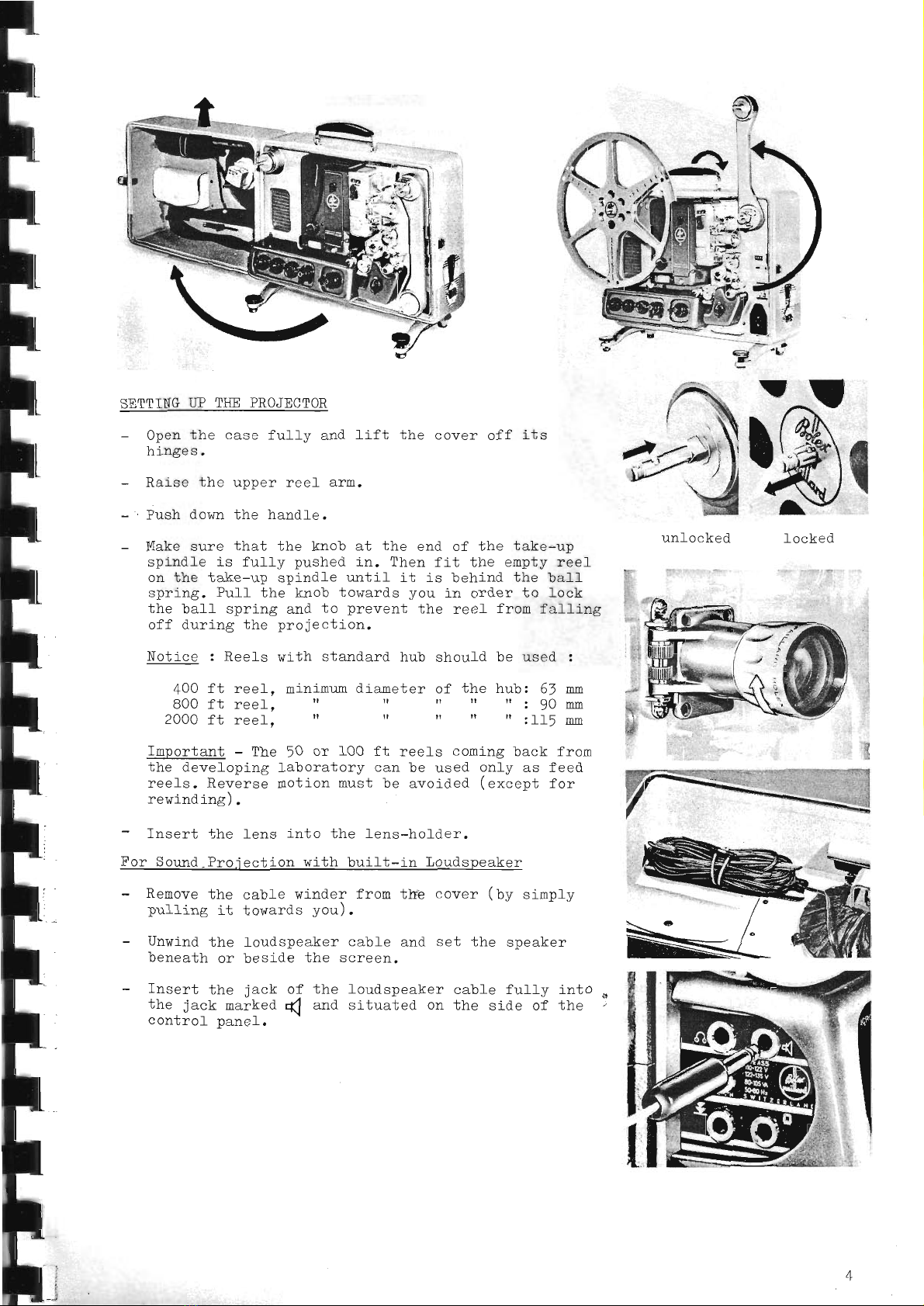
- Connection 'rio
the Electric Power Supnlv
The voltage supplied to the projector musL
be
rrA ra r?tr -.art^ If the nominal voftaee of
the focai main supply is either lower or
higher than these values (between 90 and,295
vofts, taking into consideration the over-
voftage and rmdervollage of the grid), iL
is necessary to use the Paillard-Bofex trans-
former T ff (or another auxir j-ary transformer
I <A{ I \/ n l
ua vr{urv4rsrru yuwvr f durlrt3, L.y. L,))w vA.l .
The S-22f projector rurrs on AC current. 50
or 6O c.rcles/sec. rf necessary,-Ed'j.rsT-TE6
position of the cover of ihe stroboscope ac_
cording to the figure shownopposite. To clo
thls, foosen the screw situated above the
stroboscope aperture (one turn at the utmost).
move
the cover (e.g. ffi
downwards
for 50 cvctes/sec. or upwards for
60 cyctes/sec.; Lhen r,ighben
Lhe screr,r
Lgarn,
Be careful not to press on the perforated
disk of the stroboscope. 50
^-
T F nnl rr D(l arrnnarf i c orrn i T ol-.-l ^ +-
rr vrrrJ uv uurrv[r, rs 3va-L]ao.re,
trhe projector can be used sole]y for silent proiection
unless a converter is added in order to provlde the essential AC =uppt]-fffif[-frE
amplifier (Power about lo watts, voltage z rro-r35 votts, 50 or 60 ;;;i";i;";:t-;;""'
infornation about conneeting the converter, contact your Bofex dealer.
WarninE - ff the
6Se" pase 9)
1n\
- -Buses
Check your house fuses to see if they are strong enough to stand the curent taken by
the projector. The maximrm total power consi:med-
by the prol;ector can be 11OO
watts
when equipped with a 75O watt lampl it c]inbs to about 1750 watts when a IOOO
watt
lamp is used.
The rating of the fuse must be at feast equal to the figure obtained if the total
power indicated above is divided by the supply voltage,
If other lamps or efectric appliances are l-eft switched
running, then the power they use must be added to that
calcufating the fuse rati-ng required.
60'\-
on whi I p fhc nnnionj-nr i a
vJewvvL rD
eonqtrmcd hrr *ho nrn i on*nr i n
vJvvuvL r11
s-22L projector is used with DC current, do not switch on the anpli-
in order to ar-oid blowing the fuse. (ro replace the fuse, "uu pig"

,;?Si:rlt
,i:t::r:1.
,.
- Con:feqtine up the Projec
l. Make sure that the nain switch is set to
STOP.
2, Turn the knob of the rheostat (which
regulates the amount of current fed to
the lamp) as far as it will go in the
direction shown bv the arrow.
A. Main Voltage between llO and ll5 Vofts
Withdrar,.l the power cord (
a) f itted under
the lid:nd conn-cb lhe projector direct-
ly to the power supply.
B. Main Voltase higher than ll5 Vofts or
lower than lfO Volts
Use the Paillard-Bole:', transformer T lf.
Connect cable (b) of the transformer to
the por^rer supply ancl insert the plug (c)
in the projector socket.
C. If it is desired to use the por,rier
cord
(a) :s an 6xtension cab-Le, Lhe bent plug
on it must be removed and the cord con-
nected to cable (U) on the transformer
wi Lh an appropri:te p1ug.
To Set the Voltage Selector on the Bolex
T ll Tra.nsformer
Snrew the nl rr,q
i nto 1;ho hol e nnnnsite the
wol tar"o r.ay\rte r:oweri nrr lhe I oea'l main vOl-
+^ -^ mL^ -^--; -.,* ^,.--r ,, .-^r +^ -^ ^f either
ua6s. rrrs ua^fu(,u DqyyLJ vvlua6s v.
range of the transformer is marked in r-.d
and the minimrm voltaEe in blue.
.i
fower Suppfv to Amplifier
The amplifier has a voltage selector, bhe
setting of whj-chis necessary in order to
obtain the maximum output and at the same
tlme avoid possible overv'oftages which cause
the tubes to burn out prernaturely.
ft is advisabfe to measure the voltage
supplied to the amplifier by means of a
voltmeter. Preferably use the Paillard-
Bolex voltneter (supplied on request) by
nnnnaa*-ina j.r- +^ the room'lioht.i no outtet
U VV vrrv
on the projector. In order to read the
volta.ge - nnoioct'i on I rmn mrrqt he =witched
,y-vJ!(J,4yuur
B

rr:---r:-^- rt^r.^-^ selecl,or on Amnlifier
AU tUbULtlX VUf Ud*U -------- --- -*-..
Set the selector :
- to the rrblue" position if the vol-taqe
(main or transfornoer) i-s between 110
-nA 1t) rrn-l*:
+^ rL^ rr..^irr "^SitiOn if the voftaqe
- uu uttg rEu vv
is sub.iect to frequent chanees or if
the votlage (main or tran:former) is
betsce4 -1?2 sqd 1j5 volts.
If there is no voltneier: :,,-ril-i],:tbf
e to nea-:ure
pro je ctor bf iire transfcl-::,-:.r T 11, chec:k ";he the exact volbage supplied to ihe
nominal nain voltage (shown on the
elecl,r Lci by :r+
.er o.r e b ;-c )
.
Ascertain l,rheitrer tle noruinal vol tagr:
blue ) or the na:<imr'u: vol tage (red ) of cones nearer to the mlnim:m voltage (shotntn
in
thc roltage range chosen by means of the
+rqncfrrmor nl-rc
vr 1=.
Set the selector oi -'hi..
anr,.llfier to bhe clr::responding colour.
To aL'J
jrist bhe -.'cltaEe seiector', Lrnscrer.,'
the knob, putl it forward and slide it side-
r.ra]':
'.r,til -h 1..;l:ed ccl oLlr i-c rrrgtbl:"
Then screr,r the knob -:c.,-ll :,,,-;:iin.
fn case the supcly -ilii:g: i.s not knolr,n prer:i.s:.1.;'i (no voltmeter available), it is
bos*, -':r:rl-:-.t. .1.
, - 'j, . :'.',.. :-' ',h.ttredttpositj_on.
(lonnaa* i no rrn Q nnm T rmn
LfrrF up lLvvd luuv
A room lamp can be plugged into the r.mi-
versal-type socket of the projector.
This lamp is switched off automatically
when the projection lamp is switched on
and vice versa. The room lamp outlet has
a socket for both E'aropean
and American
t;rpe plugs. Use a bul-b of I10 to l}0
volts, which is the voltage available
with the .:niversal-type socket. If the
bulb is destined for a higher vol_tage,
it will only supply a percentage of its
rnl-^*ti ^l ^..+*.-+
yuu9rrur4r wuulJuu.
The power taken by the room lamp must
not be more than :
200 r.^/s{1g
if a 1000 i*att projection
lamp is used;
f5O wa.tts if a 75O
watt pz'o.iection
lamp is used.

t
t
t
I
t
I
I
I
I
I
I
I
l
I
I
I
I
I
I
I
I
I
Pre-l-oadinE 0perat lons
- Turn the roain switch to 'IMOT".
Turn the speed selector knob
order to obtain the desired (with an arrow) in
nrnion*i nn cnoarf
- Choolr ihe r,no-io nl.i nn qnood urith thp stnntrncnnna:
vrru yf vJ!rurvrr uyvuu vrr v,L
lrho nrnionfnr nrnq qt r cnood n? 2A f n q r^r]eon
vJvvvv!vuvyvvu"'!-jf---j-j-X-3-Y..
the l-uminous dots on the inler circle of the
stroboscope appear motionl-ess.
Tho nroiontnr nrnq 2t: <nopd
vrl!uvvr v lr uyuvv
the lr.minous dots on the outer
stroboscope appear rnotionless.
nf lR f n s. when
rr D D.. -^^*- ^f the sneed solenter it is aJ"so
I3 - !v uralr- u,
nnqqilrl e tn qol oot enrr nno iont i nn qnood hoir^roan
vJvvv!vra uyuvu
16 a-,,1 2E f"r:r-s re- qecnnd hrrt 'i
n this case it
is not nnesi h lo to eheol< l.ho cnoad lrrr i:ha
stroboscope.
Switch to the position marked Q(
Warning - If, in spite of Lhe resLstance of the
r^-- -L -L. Dointer ol thol :mmeter qnes
IaUV tIIVVD Ud U
t UIIL yv---
hcwnnd tho rod or ve'l low dot nr hor16nfl that of
vr J
a different cofour corresponding to the parti-
cu-Lar nominal .rol tage of the l*p (
see f ol lowi ng
page) - 75A w or 1OO0w according Lo the type
of I a.nn psed - nrtrqs i nnad i c'f al rr ^n the knO b at
the centre of the switch in order to stop the
nraraa*^r rn-.-1-iS indiCates that the srrnnlrr
uvr r fvf urls Du},ylJ
volta.oe fed fn the nrnien'f.nr iq hiohor fhqn
lJl volts, and the lamp would be overloaded.
Tn +hic naca r!6a r l-rancfry-or nr, if One iS
alreadrr in rner:':inr ahaoL +ho n^SitiOn Of
the voltase sel-ector.
circle of the
@

I
II
l
t
I
t
I
I
I
i
l
I
I
I
I
I
!
I
Turn the knob cf the rheostat slow-
ly in the direction shown by the
arrow untlr the pointer of the
ammeter
rs facrng the red dot (f000
u or 7t. w, accord'ng ro the type
of lamp r ::-e
yellow one
when
a
ff5 V lanp Js reing used instead of
the commc-lry
used 110 V lamp.
lf nrcq ; o e .Ot altOW the
ni fLAr' av.ald rho annronrielo
rarl rr rro' r rr^r rl o-l-
y Li:! Yr uv v Pcsitlon, or
otherwise rhe lroiectlon lamp will
be over: caded and its life correspon-
diner y sh,r-,ereC.
T.i-, .:n -). n-'i6-Lor unLil Lht
pro.y-ct^,, b- r:. of f-ighL eovorl tho
screen.
To aiijust ceight, turn milfed
knob (ct),
Thc im>r, i lorro ll od rrn rn,l f ho
sy |r'rv
nnnionl nn nr':. ,*orrrrr hrr Frrnn irc
' ". 'J
/ \ /^\
Knoo.'(
I .1: (1/.
Turn the s',..'itchback to the position
STOP,
by sirnp11,.
pressing on the
centre of the s'riitch.
If you
r.ri.-h'.o:lop
the pro.iector
quickly, rr'ou
can use the motor as a
hr:ke hv qottinq l:ho cr,ritnh tomnn-
ra1115 lo Lhe oosltion "R" (reverse
motion),
If a Sound Film is to be shown
- Turn the control marked VOLIIME
to
posltion "1'r in order to swi-tch on
the emplifier. The control- panel
larnp will then light up.
The amplifier shoufd not be n.ur for
more than one hcur r,rithout switch-
ing on bhe molor, which provides
the necessary ventilation.
i:::1,
'..
,:.
,a:,,,a
).1
t.')::::.
:i
.'.::t:
f-€m
::ll,"rlirill,

F
h
I
h
I
I
I
F
I
I
I
I
I
I
F
I
It
:I
I
t
I
F
],OADING
THE PROJECTOR
The film threading diagrams on the
front of the apparatus show the paths
through which the film must be threaded
for sound proiectlon wi-th optieal trer:k
(diagram roarkedOPT) or with magnetic
track (diagram marked MAGN).
The path picked out in dots on the OPT
diagran is used to thread silent fllm.
(See illustrations, page 11 and 12).
- Place the ful1 reel on the upper
spool arm. Do not forget to l-ock it
(see page
4).
The fifm nust unwind in the direction
shown by the arrow.
When a fi1ro nith a single row of per-
forations is used, the perforations
must be on the side nearest the
operator.
- Unwind about ! feet of film (teader).
Svring the fens-hold.er out in orcler to
open Lhe
gate entirely.
Open the fi1ro guides on the three
sprockets by pressing on their
respectlve buttons (see arrows).
Draw the fi]:n onto the
and insert it between
sprocket and lts film
sure that the sprocket
the perforations.
Then simply press the
onto the fi-le.
'{
ontrrr rnl I on
tlro rrnnan
guide. Make
teeth enter
gui-de down
t
'a
10
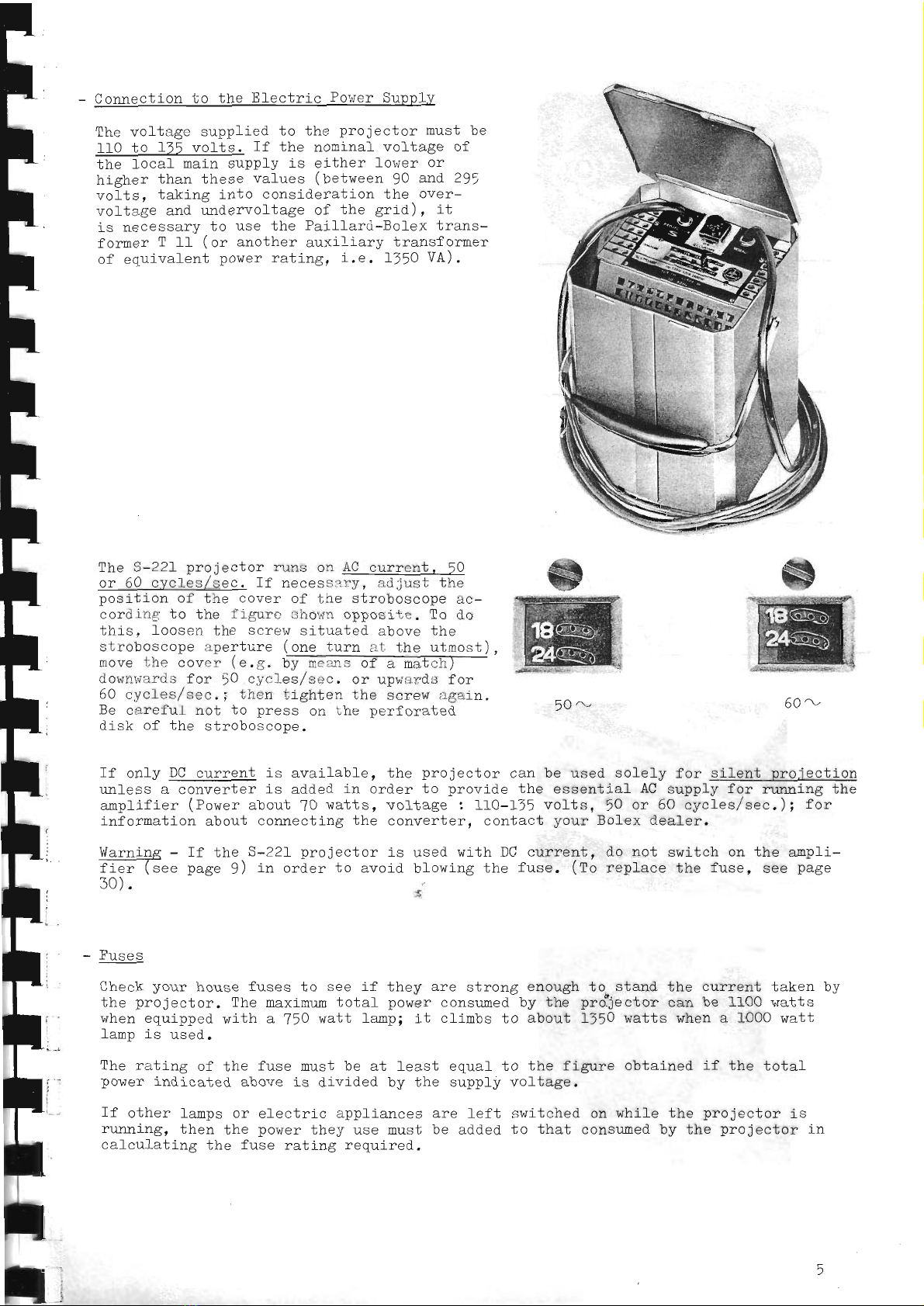
IOADINGTHE
PROJECTOR
(cont.)
- Forn the upper loop to coincicle
rvith Lhe height of the crrgrovrru
curve on the housing of the pro-
jector.
- Insert the film into the gate
betireen the film grides.
Form the lo;'.er loop to coincide
'ri I.r hh- :.
or vo'l curve on Lhe
housing oi'ir- projecLor.
Tnsert the film on the mlddle
sprockeb, :naking certain thaL the
Leeth engage gfta
perIoralLons.
Press th- l iln-guid- oown against
the film.
Close the lens-holder r,iith no re-
gard to the position of the claw.
The Fath of the film between the middle and lower sprockeL is dilferent for g silenl
Ii-Lm and for a soprr4 jilg with opbicaf or mas-netic track.
Carefully expmine the following illustrations 2
a) Fifn path for silent
nFAia^+i ^-
Irv,tvvvrvrf.
i1
t
F
l
t
F
F
l.
F
I
F
tI
I
II
T
I
tI
lI
I
II
I
I
I
I
t
l|
IOADING
TiS PROJECTOR
(cont.)
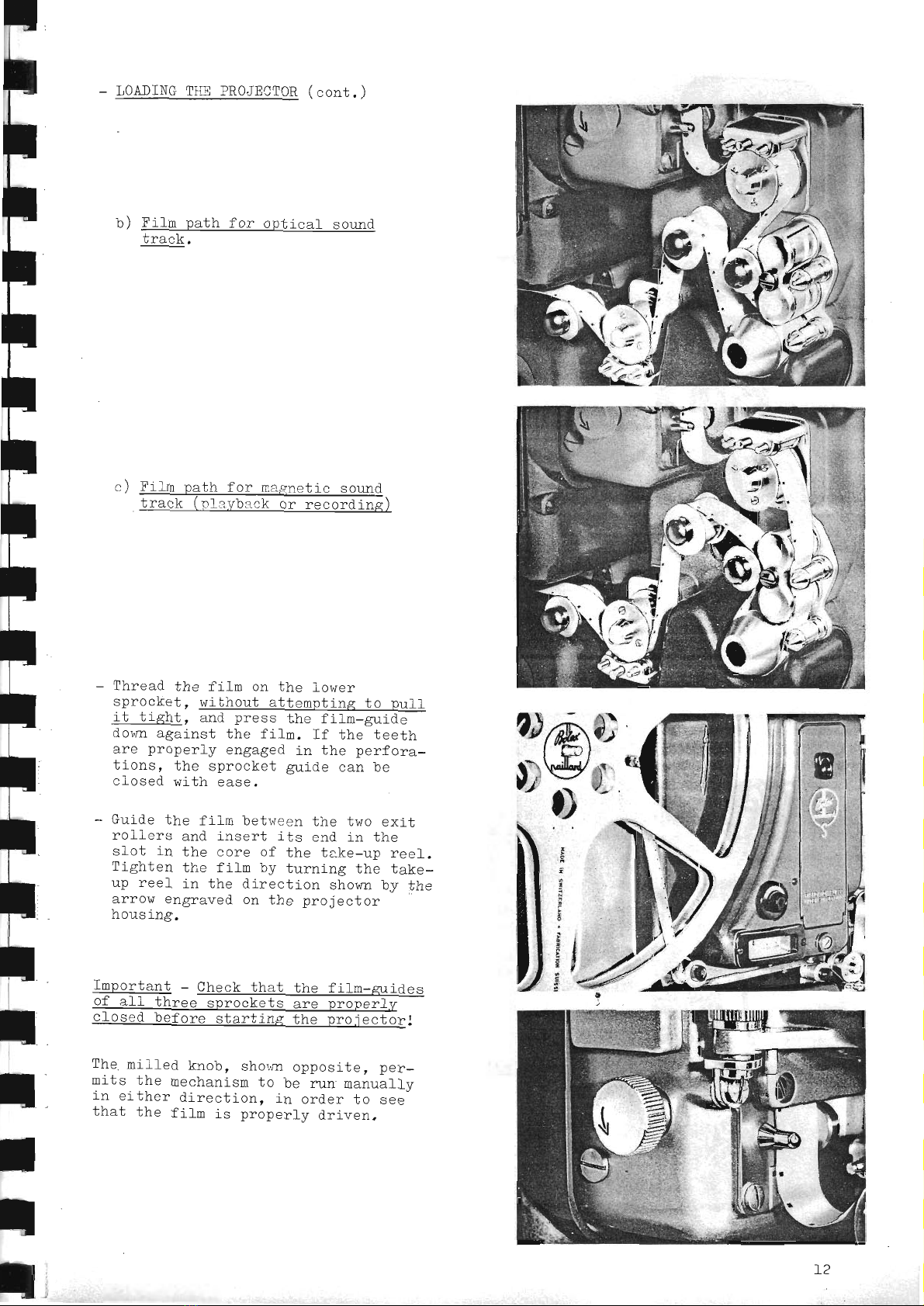
hl I'ilm n:th for nnJ-in:l qorrnd
track.
n ) tr'iI m nr f h loe m>onal in qnrrnd
track (nl avbr^k or recording)
Thread the film on the lower
sprockeb, wibhout attempting bo pull
; {- l-i tul^+ ^-i ^-^^^ LL^ fi l- -.ii^
IU UI<IiU- aM Uat-5 Ulti L Iilt-AIl |(tfi
down against the fi}n. If the teeth
arp nronerlv enrrased in lhp nerfor2-
*i nnq thp qnroolrot or-i do nqn ho
closed with ease.
Guide the film betr,ieen the two exit
roliers and insert its end in the
sfot in the core of the take-up ree1.
Tiohion l-]^o f i lm h.- !,rnrinc Fh6 +-l
- -** u./ J u t.rr r ilF, Ltle Lil.Ke-
rrn rool ir J-l.ro diron-l-inn chnr.rn lrrr'{-1-^
uy ! ut? u !L su u lurf Dllvwlr uJ lllg
anmn-ran ^- iho nnn'ionl nn
aL rvw slI6IAVgu Ul1 J-19 ],!vJsUUvr
housing.
Important - Check that the fifro-zuides
of alf three snrockets are oronerfv
cfosed before starting the proiectorl
The roill-ed knob, sho,.,rnopposite, p€r-
mits the mechanism to be rr:.n manually
in either direetion, i_norder to see
that the fitm is properly driven.
o;^e)
u'$e:
E
,
:
t;
:*
a
tl
L2
F
F
F
F
F
I
F
I
I
I
F
I'
lF
t
r
t|
I
t
T
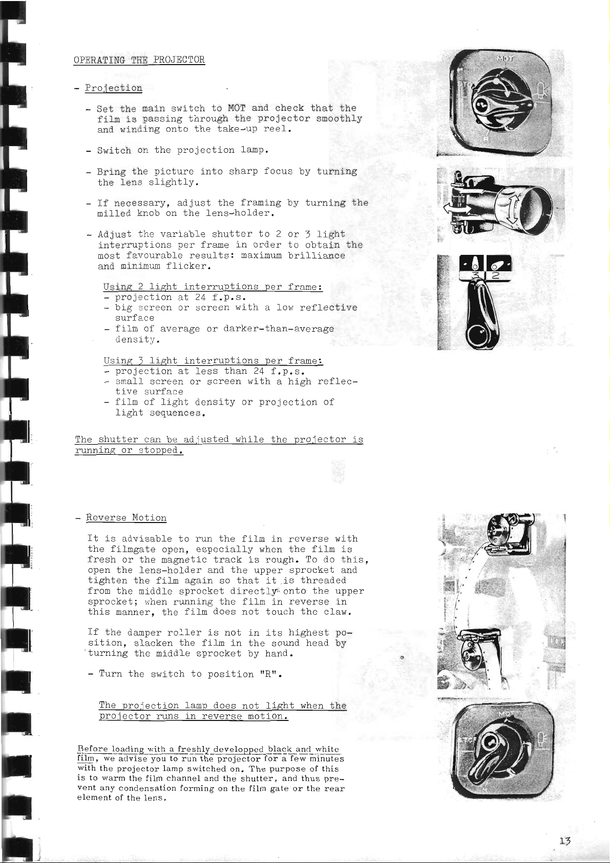
OPERATING
THE PROJECTOR
Drni onl-i nr
rrv.lvvurv4
- Set the main switch to MOTand- check that the
f i lm iq n2qqino thrnrrsh i.hc nrnicctnn qmnnfhlrr
:svv+4r5'vuvvura!.y
and lvinding onto tho tsko-rrn rtraf.
q'..if ^I.. ^n tl^a nrnianf inr-lqmn
- uwruurL u:r ulrs Pr vJsuururr raulr.
- Fr-ino lho ninf.rrno irtn qhqnn fnorrq hrr irrnrinc
, vvsv vJ
f.ho len: rliqhtlu-
Tl nocoqqcr'. pdjrtst the Fr:mino
milled knob on the ]ens-holder.
Ad
just rh-. variabl e shutter to 2
interruptrons per frame in order
nost f a.rcurabf e results: maximrm
and mininum flicker.
l.rr ]]_'.r--ir+-{-L^
u q! rf !!6 u lrs
or J light
to obtain the
brifliance
Using 2 light interruptions per framei
- projecilon at 24 f.p.s.
- big screen or screen with a low reffectlve
surface
- fiha of average or darker-than-average
ioncrtr.
Using I light interruptlons per frame:
- projection at less tlnan 24 f.p.s.
- small screen or screen with a high reflec-
tive surface
- fiho of light densi-ty or projection of
light sequences,
The shutter can be ad.iusted while the proiector is
nmning or stopped.
- Reverse Motiorr
It i-s advisable to run the film in reverse wi-th
the fihogale open, especially when the film is
fresh or thp m:qeii o trrnlr i q nn.'-]" 4rn n n *Li ^
+u rv46ft. rv uv ulrlD,
onen th p I on s-h ol d er :rd th o rrnner qnrnolroi qrrl
uyf vvau v 6rru
tighten the filn again so that it is Lhreaded
from the middle sprocket directly onto the upper
sprocket I i.rhen
running the f ifn in reverse in
this manner, the filro does not touch the c1aw,
If thq n,rnnpr
ro-rler is not in its highesh no-
sition, slacken the fil-n in the sound head by
'turning the middle sprocket by hand.
- Turn the switch to position "Rtr.
The proiection tamp does not light when the
nrniaa*nr -.-s in reverse motion.
vtv,tvvuv! rlAr
Before loacling sith a freshly developped black ancl white
Illm, we advrse you to run the projector for a few minutes
with the projector lamp switched on, The purpose of this
is to u'arm the film channel and the shutter, and thus pre-
vent any condensation forming on the fi.lm gate or the rear
element of the 1ens.
i+;.!
=dht'it,
rin:r*
':ti,gt&
i::&i;
il
&sb-
ti
F
F
F
F
F
F
F
II
t
I
I
I
rt
t
r
t
t
t
I
I
t
I
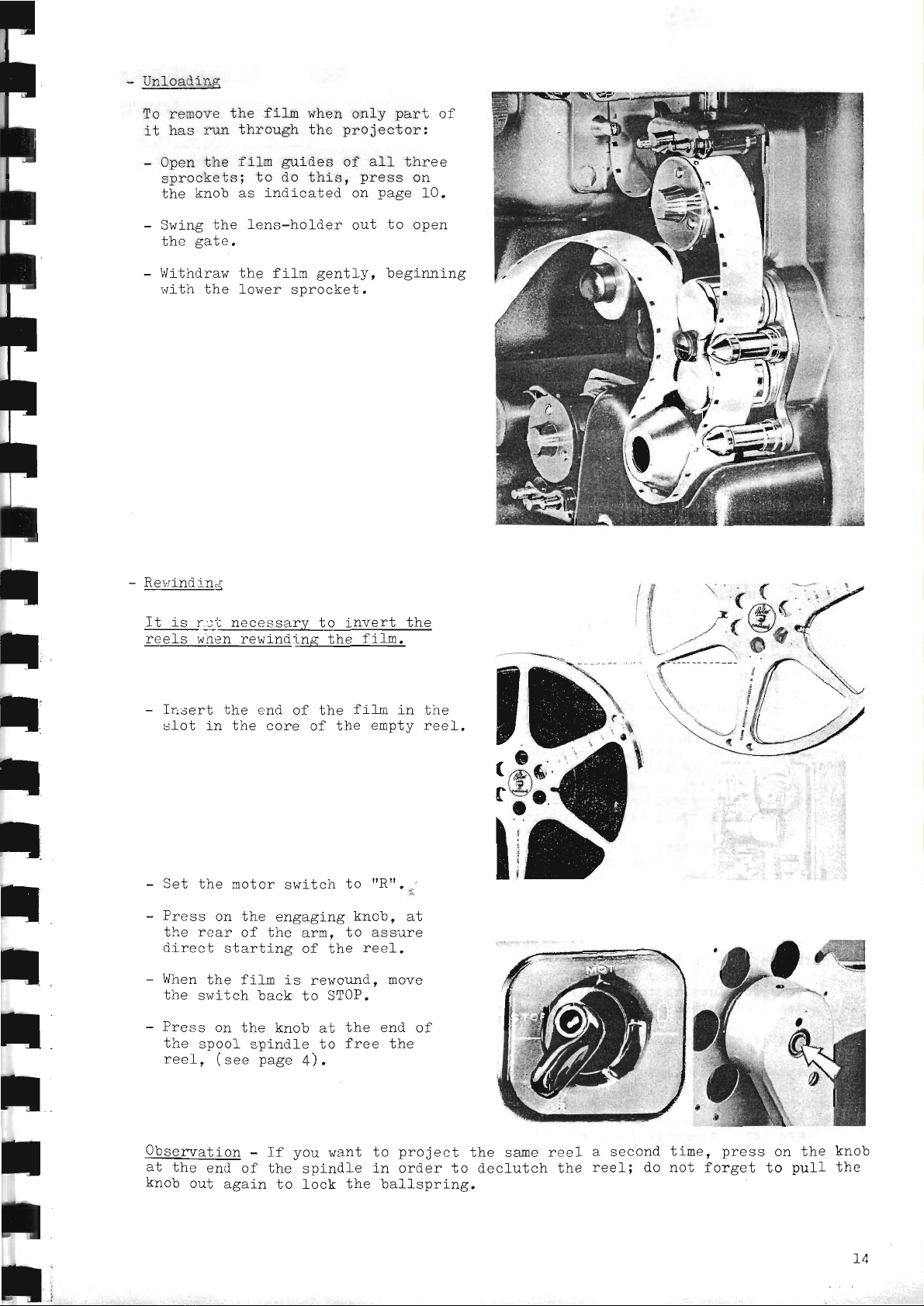
TTn-lnod i ns
To remove the filn when only part of
it has n-m through thc projector:
- Open the fifn guides of all three
sprockets; to do this, press on
the knob as indicated on page 10.
- Swing the fens-holder out to open
the gate,
- \{ithdraw the filn gently, beginning
rsith the lower sprocket.
Revindln;t
It is r:lli: necessary to invert the
reels r.rnenrewindi--qg_lhe__€.ific.
- Insert the end of the fil,n in the
slot in the core of the empty reel.
Set the motor switch to ttRt'
. .,.
Press on the engaging knob, at
the rear of the arm, to asstre
Cirect starting of the ree_1.
V/hen
the fifm is rewor-lnd, move
the switch back to STOP.
Press on the knob at the end of
ihe spool spindle to free the
ree1, (see page 4).
Obserwation - If you want
at the end of the spindle
knob out again to lock the
to nrnion-i tho qer^ F^^-l
vv }Jr
vJuw u urru rdv I YgI
in order to decl-uteh the
ballspring.
a second ti-me, press on the knob
reell do not forget to pull the
I ,.f
t,l
;,1
i
'1
\
i:r
I
h1
nt
'ir6o
,AYf
,ill
\----idl
'\- c'-\--"
(
r
14

F
F
l
I
I
I
l
I
F
I
I
I
:I
I
l
I
t
t
MINOR
REPAIRS
OF PROJECTOR
TROU-Bln
The rootor w111 not rurt,
f l,ro clrnhnoann6 dnac nn+ l i ml"t
Lttu -utvuu-uuvg uvgD tfvu 1I<i] u.
no current is reaching the projector.
The motor stops as soon as the switch
i s set to rr
I anntr q11
.
Tha I qmn dnoq nn* 'l-i
ohi rrn
v 416rr u uP.
The motor nlr1s, but the lamp 6e"" rtoa
-1 i -1.r* rrn
-+=69_9__-t4.H.l-
The mninr :ni nrnioniinn lqmn lrnfh
",, oDe-
rate, but the control panel does not
I iqht rrn r"rhon the VQLLTlvlE
control iS
sr^ritched on.
The control panel- d.oes
not tisht uo.
afthough the anpLifier works,
The screen is r.msufficientfv lighted.
The pointer of the ammeter does not reach
the red dot (1000 or IJA .,r
depending on
the type of lamp), when the rheostat
knob is tr.rned fullv in a clockwise
direction.
The screen is ulevenlv itluminated.
PROBABIE CAUSES
- The house fuses have burnt out.
- The connection cord is faulty.
- fhe transformer cord ls faulty.
- The transformer fuse has burnt out. o:r.
the sefector plug is r_utscrewed.
The horrse fuses have burnt out, they are
not strong enough to take the current drawn
by the projector (see page 5).
Faulty projection lamp (filament burnt out).
To change the -Lamp,
see page 2!.
The amplifier fuse has burnt out. Check the
voltage with a voltmeter (see page 29) and
change the fuse.
The control panel light is faulty. To change
it, see page 30.
- The projection is din (glass bulo
blackened). Change the lamp.
- The supply voltage is too lorr. Check it
with a voltmeter.
- The projection lamp filament is not
centered (see page 2g).
- The lamp is not turned in the proper
dj-rection on its stand (see page 29).
- There is ilirt on the projection lens, the
conclenser
or the reffector (see p. 27-28),
- The screen is of poor quality,
- The room is not dark enough.
- Th^ rear len: element of the projection
lens is moist from condensation. Keep the
n rn i 6af nr nrnn-i no f nn qnmo mi nrrf
pr \/JUUUUj tWulr-^b ,-- ---- .-r,,*-es,
rrrhi_ler
the lanp is lit. If necessary,
clean the lens gently with a cfean cl-oth
or the special paper sold in the photo
st ores
.
- The film is of poor quality.
- ?he film is d.irty. Clean il with a
special cleanser, obtainable in photo
stores.
- Ihe film ls damaged
or its quality is
poor.
- The gate is gu,mmed
up with emu1sion
deposits (see page 2J).
- Tho film ic noJ- dnirran nrnnor'lrr
f v vrf yr vyvL LJ ,
owing to;faulty loadi-ng (see page 10).
- One of the film sprockets is not properly
cfosed.
- The film perforations are danoaged,
- The film has been badly spliced.
- The fl1m has been tightenecl too much
during load ing between the sormd drum
and the fower sprocket, (see page 12).
The pictures on the screen lack
f,
The nicfrrros tro nnnqcinnqllrr
rr-n:,* -^n--
lA1u usau y .
The ttnnon nr fha lnr^ror lnnn
-4!v 4Vpv! vt urlg rvwgf lvuu
di-sappears.
tq
PROJECTION OF OPTICAI SOUND
PRINTS
- General
Th6 q-.tl nnnia^167 'i
s desi rrned to take al I trrneq nf f6
vJ! v uvr
:) Orisina-l rewers:l nrints and nntinql annioc
gl4la9vUJvgrvvyfva.
During ]oading. the emulsion faces the screen.
b) Contact prints.
T)rtrinp logdin- +L^ ^-..r^r^- 4^.oq iho lomny4r rfr< fvqu!r-F. utfg guuf,atvII f avco ullc t-.ilru-
The emulsion can easily be distinguished fron the base,
The optical track can be either of variable densitv or
(pusn/puLI,)
tracK/.
mm
filn with optical sormd track :
as its surface appears dulfer.
rrarirhl ^ ^?6t lcim-ra nr a.-l+i-l^
ar ea \ oruPrs vf uuf urp Le
The varlations in light intensity transmitted by the sound head to the photoelectrlc cell are
converted into sound waves after amplificatlon.
;
t
t
t
t
t
l
t
t
t
;
;
;
Variabfe densiLy
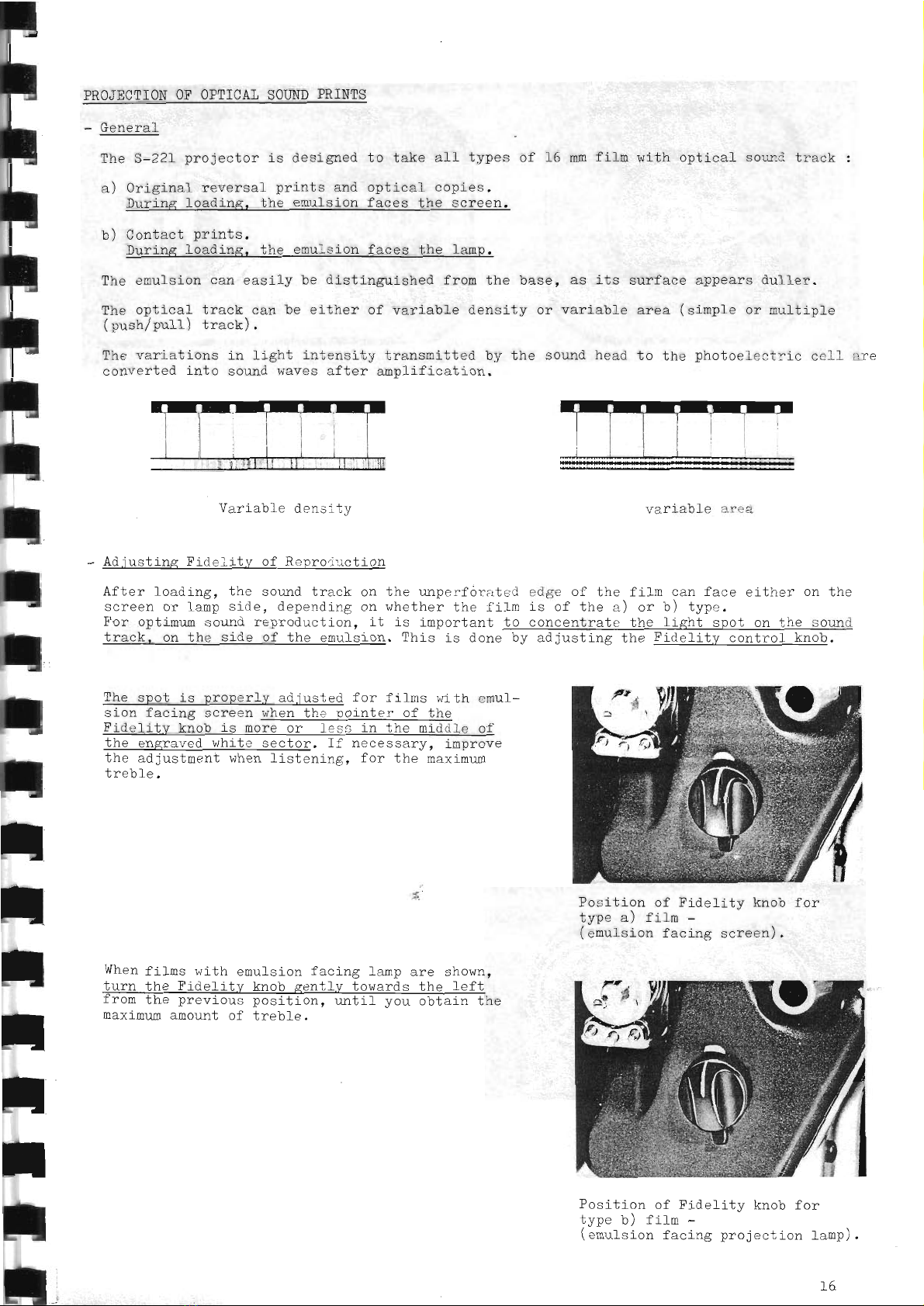
Adjustjns Fidelitv of Reproducti
on
Af her 'l
nad
i ng. tho g6111d
Lrack On
qaroon nr _lqmn cida donorr'lirc nr
trtnr on I i mrrm qorrnrJ ronnndrrn I i nn i t
Lrr vv4u !tv!!,
l-fASF, on the s ide ol' tl"e etrulsion.
variable area
the unper-[orabed edge o-[ t]re litm can face e-Lther on the
whether the flfrn is of the a) or b) type.
-is imporLant to concentraLe bhe light spol on jhe sor.urd
This is done by adjusting bhe Fidelit.v control knob.
The spot is properlv ad
jusled for f i Lmsr,ri
Lh emul-
sion facing screen q[q4 the poinler of Lhe
Fide-Lity knob is roffire of
bhe engraved wh-Lte
sector. lf necessary, improve
the adjustment when listening, for the maximum
When fifns r,vith emulsion facing famp are shown,
lurn the Fidel.itv knob eentfy towards the feft
rrom the previous position, unLif you obtain the
maximrm amount of treble.
Position of Fldelitv knnh fnr
typ" ' j--rit'- -- -
(emulsion facing screen).
Position of Fidelitv knob for
type bi larm -
(emulsion facing projection lanp).
16

E
F
F
I
F
F
F
F
l
I
F
I
I
;I
t
I
t
t
.-',
lt,.-,;i,,*..:-r'o;.,,;tlt *;*;**4i-li;;..r,;;jt
- Projection
For o'ptical sound reproducbLon. the proieclion rate must be set to 2-l frames per second
- Sel lhe fidelily cor-tro-Lknob according to the Lype ot' f
i'lm to be scre-ned (see
preceding page),
- Set the selecter srritnh to OpT Ffl
,.""
"..
\
light up.
c^r +h- 5':F ^neraijng:..1 ..,.:h l,o IvlOT
' 'r uy-
^ij..-r +L- .^,-d frnt :r., h,l na:rS gf- nuJuJU rllc Jw4lu u,/ rLdr-r
Remarks :
Thc o":itor lamn nf hho onl'col sn91ll63d vrLLl
qrd I hon fn flt f nrnionl i nr I r-n n.l
\rrvJr tLUP vL!/.
the VOIUIW control.
is run on its rated
mrvimttm n6lrar nf 6 -''oi-{
^
u wd u uJ,
thi. l6ll,fcponlapn iS USed
P!ul}vr
in ilro cnoairor
The amplifier can supply an output power of f5 watts (if it
+i-* r-^tr- -.)
uyqL aurrr€i vv r
uaais/ .
Slnoo Lhe Inrllsno3ftgr bui]t intO the nroiechor lakes onlv a
ihe sound rrolume shouid not be set beyond a certain ]evef if
:lone. in nrdor to avoid disborlion:nd erren nossihr- r-r--^
aivfrst rlr vrusr uv avvlu uL-uvf uf,vrf Gfru uvrrr [/voJruLc udud€3s
AAi,.^+-^-+ ^€ m.
- ALr,
j
us LnenL oI fone
- knob a (bass)
- knob b (treble)
Al a rrerer"l n:l e. +,1^e nnr-p^t. hql an-
ce between bass and treble is obtain-
ed when the red markings on the tone
controf knobs are set about mid-way.
Soroe
adjustraent of tone is sometirnes
necessary, however, depending on the
acoustics of the room, the quality of
the recording and the characterisLics
of the loudspeaker used.
The bass and treble registers can be
relnforced or reduced in strength by
ntr7"pl rr t'r nni r c f lec nnrroqnnnd i no
r r JPwIurrL6
tone control knob in the appropriate
direction. Number
"fO" corresponds to
the maximr:m
amount of treble or bass
avaifable.
L7
E
F
;
F
F
F
F
F
F
I
I
I
II
r|
t
I
t
t
PIJBIIC
_ADDRESS
SYSTEM
It is sometimes effectlve to use
hpck.oroundwhen the sound track
vuvr+b!
when showing a silent fi1m.
- TIco n{- Mi^r.nhnne
- t,Ds vr rrrvr vPrrv
Insert the microPhone jack in
phone input @ on the rear of
tor. This is a high imPedanr:e
live narration i+hile a
nqrr-i oq qnoonh nnl rr nr
uyv v rrr
film is shovrn, to ad.d.
a musical
to dub in both music and speech
the micro-
l-ho nrnion-
input.
Use of the Paiflard-Bolex microphone,
-,'nnt i o,i nr FA^116q L i s ronnmrand o.1 , ThiS
ouPyr r
uni-direcLional type microphone, bhe Ln-
pedance ol which is 50 k ohms, is especial-
'I
rr of 1-:af irro r^rhon I ho nnmmonl qrv la cnnlron
in the projection room ltself. The risk of
setting up an acoustical reaction between
microplone and speaker can be ninimized by
refraining -[rom turning the front (a) of
the microphonetowards the speak.r. This
microphone lrill not pick up noise from the
projector if it is turned in a suitabfe
dir--ct ion.
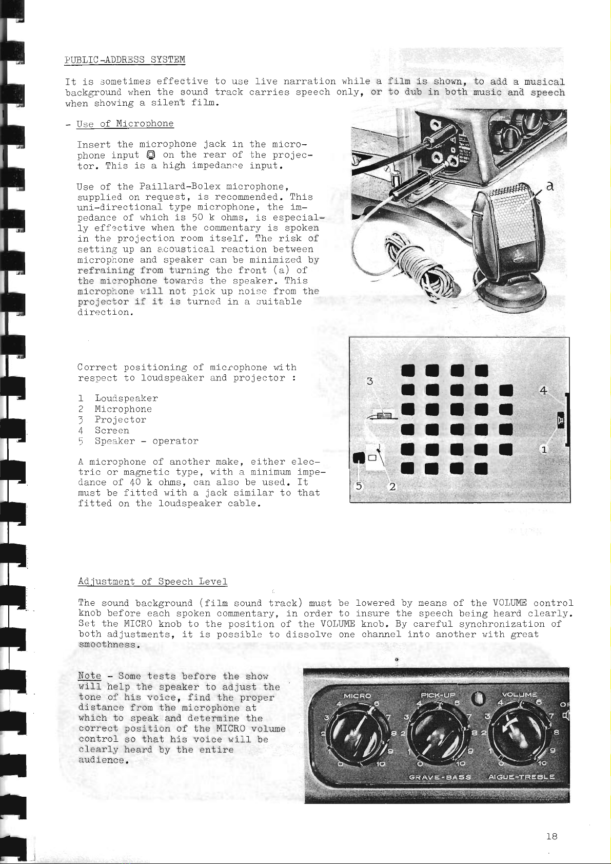
Cnpa^f nocitionlrs ol- mreronhnno brith
rasnFn- Ln I or:dsneake- rr.l nrni^r:l,of :
! vvP\ \
I T,nrrd
qno:lror
2 Mi nrnnhnna
" Drnian*nn
zf Screen
: Snockor - nnonaLof
A ninronhone of anofl..pr mako. oither e-Lec-
trin nr mampl-.io trrnp uril.h : mini
-.rI,, - *,---mum ampe-
dance of 40 k ohms, can also be used. It
must be fitted wi-th a jack similar to that
fitted on the loudspeaker cable.
Adirstnon+. nf Sncggh LeveI
The sound backgrouna (fifn sound track) nust be
knob before each spoken commentary, in order to
Set the MICRO
knob to the position of the VOllllvIE
both adjustments, it is possible to dissolve one
smoothness.
lowered by means of the VOI,ulm control
inqrrre J:hc sneech hoino ho:rd r.learl rr-
k-nh. Rrr nerofrrl sw.chroniz.ation of
Drrv v . !J
channel into another with sreat
{
Note - Sone tests before the show
will help the speaker to adjust the
tone of his voice, find the proper
dj-stance frorn the microphone at
which to speak and determine Lhe
c:orrect nosi i-.i6n Of the MICRQ vol_ume
control so that hls voice will be
clearlv heard hv the entire
- -.-*_ *J
audience.
IB
Table of contents
Other BOLEX Projector manuals


