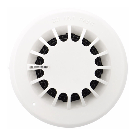
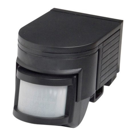
Bolid Security Systems S2000-PIK User manual

S2000-PIK
Addressable Ceiling Mount
Volumetric PIR Motion Detector
INSTRUCTION MANUAL
GENERAL
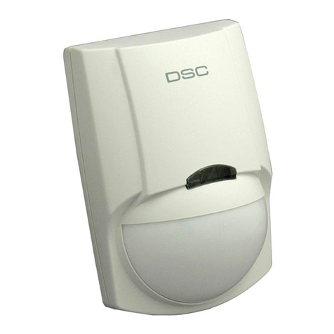
S2000-PIK Addressable Ceiling Mount Volumetric Passive Infrared (PIR) Motion Detector (hereinafter referred to as the
detector) is designed to be used indoors (within shops, offices, museums, apartments, etc.). It detects intrusion into
protected areas and sends an alarm message to the connected S2000-KDL controller via the two-wire multiplex
addressable polling loop.
The detector is intended to work as a part of an Orion Integrated Security System.
The detector provides increased immunity against lighting and radio frequency interference.
KEY FEATURES
Ceiling Mounted
Employs two dual-element pyro-electric infrared sensors
The special lens provides the volumetric detection zone with high-density coverage offering high probability of
detecting an intruder in every direction
Protected against insects entering to the pyro-electric infrared sensors
Microcontroller signal processing
Powered via the multiplex addressable polling loop of the S2000-KDL
Supports DPLS_v2.xx protocol
SPECIFICATIONS
Detection Range Coverage diameter of 9 m at 5 m mounting height
Detection Area Volumetric, cone-type, 10 far/ 1 mid/ 1 near zones
Optics Fresnel lens
Input Voltage (from a S2000-KDL) 8 ÷ 10 VDC
Current Consumption (via the loop of the S2000-KDL) 0.5 mA max when indication is off
Operating Temperatures −30 to +50°C
Humidity 95% at 25°C, non-condensing
Overall Dimensions (diameter x height) 105 ×45 mm max
Weight 0.1 kg max
MOUNTING LOCATION CONSIDERATIONS
Considering a location to mount the detector, please take
into account that the detection zone must not be obscured
by curtains, curtain tracks, door moulding, glass
partitions, etc.
Do not locate the detector where it can be exposed to
false alarm sources such as: air conditioners, heaters,
radiators, etc.
The maximum mounting height is 5 meters.
Wires of the multiplex addressable polling loop should be
located away from high-voltage electric cables.
The view of the detection area is shown in Figure 1.
Figure 1: Detection Area
10 m
9 m
5 m

INSTALLING THE DETECTOR
1. Release the front detector cover by turning it counterclockwise until
stops in the notch at the outer end of the rear cover, and then
remove the cover (see Figure 2)
2. Remove the PCB, pushing the detent
3. Drill out the required holes in the rear cover (see Figure 2), the
holes being used to mount and to wire the detector
4. Having selected the mounting location, mark the positions of the
fixing holes taking into account mounting holes in the rear cover,
and drill holes at the marked places
5. Insert wires into the wire hole leaving some centimeters for
connecting wires to the terminal blocks
6. Fix the rear cover at the selected place
7. Finally, put the PCB and the front cover on their places
Figure 2: Rear Cover and Front Cover of the Detector
WIRING
Figure 3a shows the way to connect detector’s PL
contacts to the relevant contacts of the S2000-
KDL.
Figure 3b shows the wiring diagram for
connecting the detector to the multiplex
addressable loop of the S2000-KDL controller
which is in turns connected to the network
controller and the power supply.
a) Connection Terminals
b) Detector’s Wiring Diagram
Figure 3 Connecting the Detector
PROGRAMMING
The S2000-PIK to operate properly within two-wire addressable loop of the S2000-KDL controller, it must be assigned to
a unique number 1 to 127 within the loop – the address which is stored in the S2000-PIK non-volatile memory. This
address provides identifying the detector by the S2000-KDL controller. Moreover, the monitoring strategy must be defined
which will be used by the S2000-KDL controller while processing signals received from the S2000-PIK.
Programming the S2000-PIK Address within the S2000-KDL Addressable Loop
An S2000-PIK is supplied with the default address of 127. This address value can be changed using either S2000(M)
console tools or PC tools such as UProg Configuration Tool.
In order to program the unique S2000-PIK loop address, connect it to a S2000-KDL controller which is in turns connected
to a network controller (an S2000(M) console or PC under UProg software). Then send one of the following commands to
the S2000-KDL controller (for getting more information see the relevant User’s Manual):
Change the Device Address Use the Change Device Address command specifying the old detector address and the
new detector address as the parameters (see more information in the referred
Manuals). The network controller will display the messages about disconnecting the
device with the old address and then detecting the device with newly programmed
address.
1
2
GND
+12
V
1
2
B
A
S2000(M)
Power Supply
1
2
GND
+12
V
S2000-PIK
1
2
−
−−
−
PL
+
PL
5
6
−
−−
−
PL
+PL
1
2
+U
GND
S2000-KDL
3
4
RS
-
485A
RS
-
485
B

Program the Device Address If the device address is unknown or two devices have the same address then use the
Program Device Address command specifying a required address as the parameter.
Then remove the detector cover and ensure the LED is flashing indicating
programming mode (frequent short flashes every 2 s). Next, press the tamper switch in
LLLS pattern, where L stands for long pressings (longer than 0.5 s) while S stands for
short pressings (shorter than 0.5 s), pauses between pressings not exceeding 1s each.
If the address has changed successfully, the LED will be lit steady and a message
about detecting the device with the newly assigned address shall be displayed by a
network controller (S2000(M) or UProg Configuration Tool). If you failed to assign the
address, wait for 2 s and repeat programming.
Programming the S2000-KDL to Operate the S2000-PIK
To handle signals from an S2000-PIK correctly, the S2000-KDL controller which the detector is connected to must be
programmed with the Zone Type parameter for this S2000-PIK being set to value 4 (Intrusion), or 5 (Intrusion with
Tamper Check), or 7 (Entrance), or 11 (Panic), or 6 (Auxiliary). To program the S2000-KDL, connect it to a PC under
UProg Configuration Tool and follow the relevant programming instructions in accordance with the S2000-KDL User’s
Manual.
WALK TEST
Connect the detector to the multiplex addressable polling loop as shown in Figure 3a. Then power on the controller and
wait for about two minutes. Next, walk through the detection pattern with the speed of 0.5 m/s to 1 m/s. The detector
should issue an alarm and its LED should flash. Wait until the LED finishes flashing, and then begin crossing the
detection pattern from another side. The detector should issue an alarm. If nobody is moving within the detection pattern,
no alarms should be issued.
ENABLING/DISABLING LED INDICATION
LED indication can be controlled either via a PC or by means of the detector tamper switch.
If LED indication is to be controlled via a PC, by the connected S2000-KDL, the S2000-KDL should be specifically
configured from the PC using the UProg Configuration Tool. The parameter Device Indication Control of the S2000-KDL
polling loop input zone which is assigned to the S2000-PIK should be set to a proper value. By default, Device Indication
Control is set to the value of 1, providing LED indication in accordance with the detector’s own pre-determined algorithm.
To disable indication, set this parameter to zero.
If LED indication is to be controlled by the tamper switch, the algorithm is as follows. On detector’s switching on the LED
indication is enabled (unless the input S2000-KDL zone assigned to the detector is configured with disabled indication).
To disable indication, press the tamper switch in LLSL pattern; otherwise, to enable indication, press the tamper switch in
LLSS pattern, where L stands for a long pressing (longer than 0.5 s) while S stands for a short pressing (shorter than 0.5
s). Pauses between pressings must not exceed 1 s each.
WARNING
To ensure proper operation, perform testing the S2000-PIK detector annually as described above.
ZAO NVP Bolid, 4 Pionerskaya Str., Korolev 141070, Moscow Region, Russia
Phone/fax: +7 495 775-7155
www.bolid.com

BOLID ONE YEAR LIMITED WARRANTY
Bolid Company and its divisions and subsidiaries («Seller»), 4 Pionerskaya Str., Korolev 141070, Moscow Region, Russia warrants its
security equipment (the «product») to be free from defects in materials and workmanship for one year from date of original purchase,
under normal use and service. Seller’s obligation is limited to repairing or replacing, at its option, free of charge for parts or labor, any
product proven to be defective in materials or workmanship under normal use and service. Seller is not responsible for results where
the product is used improperly, where it is used for any application it is not intended for, used under unacceptable environmental
conditions and mishandled or stored under improperly. Seller shall have no obligation under this warranty or otherwise if the product is
altered or improperly repaired or serviced by anyone other than the Seller. In case of defect, contact the security professional who
installed and maintains your security equipment or the Seller for product repair.
This one year Limited Warranty is in lieu of all other express warranties, obligations or liabilities. There are no express warranties,
which extend beyond the face hereof. Any implied warranties, obligations or liabilities made by seller in connection with this product,
including any implied warranty of merchantability, or fitness for a particular purpose or otherwise, are limited in duration to a period of
one year from the date of original purchase. Any action for breach of any warranty, including but not limited to any implied warranty of
merchantability, must be brought within 12 months from date of original purchase. In no case shall seller be liable to anyone for any
consequential or incidental damages for breach of this or any other warranty, express or implied, or upon any other basis of liability
whatsoever, even if the loss or damage is caused by the seller’s own negligence or fault. Some countries do not allow limitation on how
long an implied warranty lasts or the exclusion or limitation of incidental or consequential damages, so the above limitation or exclusion
may not apply to you.
Seller does not represent that the product may not be compromised or circumvented; that the product will prevent any personal injury
or property loss by burglary, robbery, fire or otherwise; or that the product will in all cases provide adequate warning or protection.
Buyer understands that a properly installed and maintained alarm may only reduce the risk of a burglary, robbery, fire or other events
occurring without providing an alarm, but it is not insurance or guarantee that such will not occur or that there will be no personal injury
or property loss as a result. CONSEQUENTLY, SELLER SHALL HAVE NO LIABILITY FOR ANY PERSONAL INJURY, PROPERTY
DAMAGE OR OTHER LOSS BASED ON A CLAIM THE PRODUCT FAILED TO GIVE WARNING. HOWEVER, IF SELLER IS HELD
LIABLE, WHETHER DIRECTLY OR INDIRECTLY, FOR ANY LOSS OR DAMAGE ARISING UNDER THIS LIMITED WARRANTY OR
OTHERWISE, REGARDLESS OF CAUSE OR ORIGIN, SELLER’S MAXIMUM LIABILITY SHALL NOT IN ANY CASE EXCEED THE
PURCHASE PRICE OF THE PRODUCT, WHICH SHALL BE THE COMPLETE AND EXCLUSIVE REMEDY AGAINST SELLER. This
warranty gives you specific legal rights, and you may also have other rights which vary from country to country. No increase or
alteration, written or verbal, to this warranty is authorized.
Other Bolid Security Systems Security Sensor manuals
Popular Security Sensor manuals by other brands

DIGMESA
DIGMESA FHK-LCD operating instructions
Honeywell
Honeywell Ex-Or MLS2500CDR Installation and commissioning instructions
WHITECROFT LIGHTING
WHITECROFT LIGHTING COMRG COMMAND G Series Installation and commissioning instructions

schmersal
schmersal CSS 34F0 operating instructions
Detection Systems
Detection Systems Security Escort SE88 Series user guide

Pima
Pima GBR743 installation instructions
