Bolin Technology DANTE AV D Series User manual

1
D Series
DANTE AV PTZ Camera
USER MANUAL
Part Two: Dante AV Use
VERSION: D-09232021
D412
D220
© 2021 Bolin Technology

2
Contents
PRIOR TO USE........................................................................................................................................................................... 4
EQUIPMENT TO PREPARE .................................................................................................................................................................... 4
DANTE CONTROLLER INSTALLING AND UPDATING .................................................................................................................................... 4
NETWORKS AND SWITCHES.................................................................................................................................................................. 5
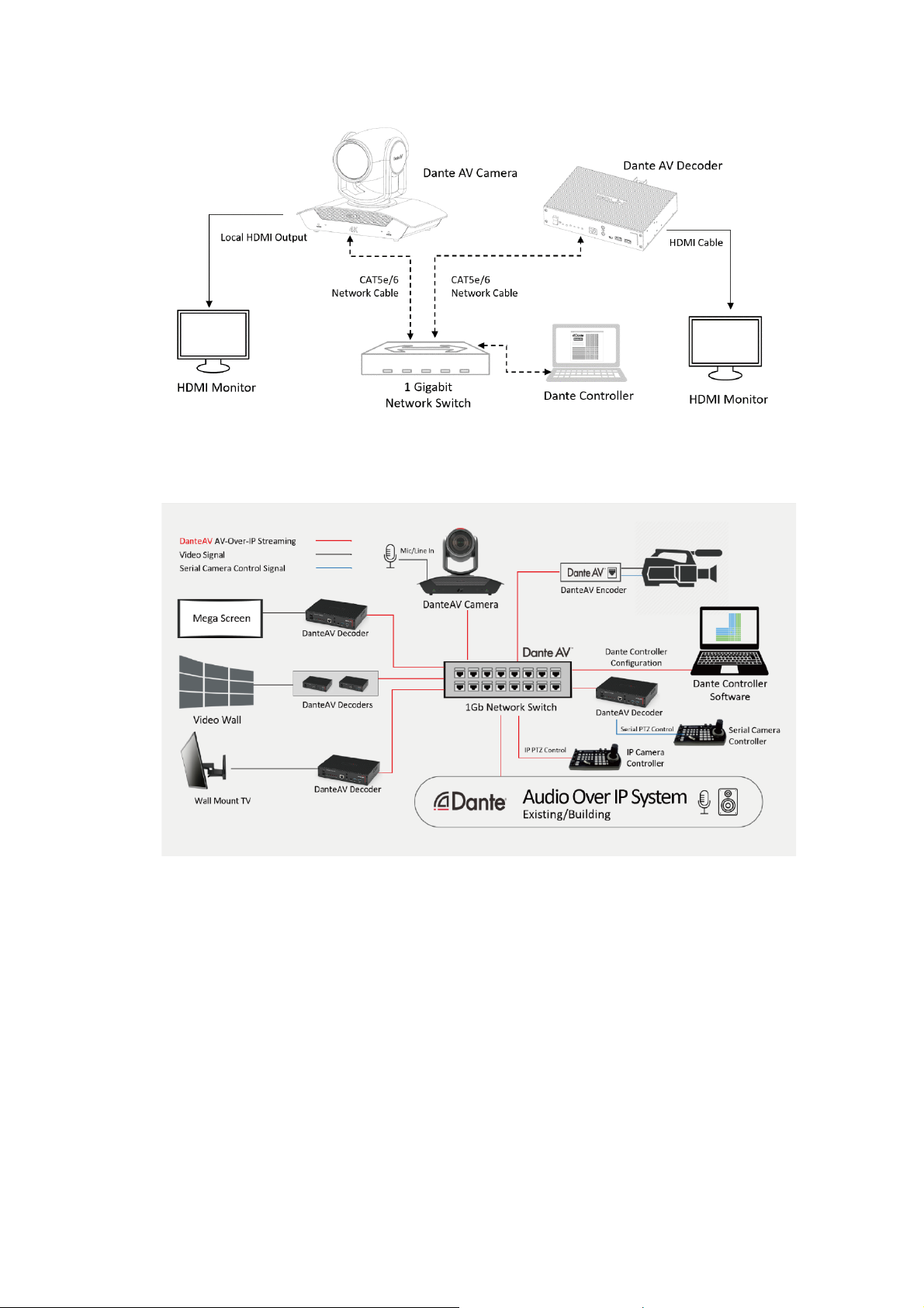
DANTE AV CONNECTION BASIC SYSTEM DIAGRAM .................................................................................................................................. 6
USE FOR THE EXISTING DANTE AUDIO OVER IP SYSTEM ............................................................................................................................ 6
DANTE AV –VIDEO ROUTING ................................................................................................................................................... 6
DISCOVERY AND AUTO-CONFIGURATION................................................................................................................................................. 6
USING DANTE CONTROLLER FOR BOLIN DANTE AV DEVICES .................................................................................................... 7
ROUTING FOR VIDEO DEVICES.............................................................................................................................................................. 7
NETWORK VIEW................................................................................................................................................................................ 8
ROUTING VIEW ................................................................................................................................................................................. 9
DEVICE INFO..................................................................................................................................................................................... 9
CLOCK STATUS ................................................................................................................................................................................ 10
NETWORK STATUS ........................................................................................................................................................................... 10
DEVICE VIEW.................................................................................................................................................................................. 12
TRANSMIT TAB................................................................................................................................................................................ 15
.................................................................................................................................................................................................... 15
STATUS TAB.................................................................................................................................................................................... 16
LATENCY TAB.................................................................................................................................................................................. 18
DEVICE CONFIG TAB......................................................................................................................................................................... 19
VIDEO CONFIG TAB.......................................................................................................................................................................... 22
.................................................................................................................................................................................................... 24
.................................................................................................................................................................................................... 24
SERIAL CONFIG................................................................................................................................................................................ 25
.................................................................................................................................................................................................... 25
NETWORK CONFIG TAB..................................................................................................................................................................... 26
.................................................................................................................................................................................................... 26
FLOW INFORMATION........................................................................................................................................................................ 27
UNICAST /MULTICAST TRANSMIT FLOW CONFIGURATION....................................................................................................................... 27
AUDIO ROUTING..................................................................................................................................................................... 30
CAMERA AUDIO .............................................................................................................................................................................. 30
FIRMWARE UPGRADE............................................................................................................................................................. 31
DANTE AV MODULE FIRMWARE UPGRADE........................................................................................................................................... 31
DO NOT USE DANTE UPDATER............................................................................................................................................... 34
MCU FIRMWARE UPGRADE .............................................................................................................................................................. 34
PTZ CAMERA CONTROLLING ................................................................................................................................................... 35
USE IR REMOTE CONTROLLER............................................................................................................................................................ 35
.................................................................................................................................................................................................... 35
.................................................................................................................................................................................................... 37
USE IP PTZ CONTROL ...................................................................................................................................................................... 37
USE BOLIN PTZ CAMERA CONTROLLER ................................................................................................................................................ 38
CONTROLLER SETUP:........................................................................................................................................................................ 38
USE BOLIN PTZ CONTROLLER FOR IP CONTROL ..................................................................................................................................... 39
ADDING A VISCA-OVER-IP CAMERA TO KEYBOARD ................................................................................................................................ 40
CONTROL THE VISCA-OVER-IP CAMERA............................................................................................................................................... 41
USE BOLIN PTZ CONTROLLER FOR SERIAL PTZ CONTROL ........................................................................................................................ 42

3
Part Two: Dante AV Use
The following assumptions are made for this section of the manual that involve the usage
of Bolin Dante AV devices.
•There is an existing operational (new designed) Dante Network that is
ready for Dante AV PTZ camera and decoder installation
•Dante Controller has been properly configured for the existing Dante
Network prior to Dante AV installation
•The operator/reader who is going to utilize the DanteAV devices has
moderate understanding and installation expertise of the Dante Audio
over IP system
If the above assumption applies to your application, please continue to the Prior to Use
section.
If the above assumption does not apply to your application, please view the information
below.
If you are interested in building a completely new Dante / Dante AV ecosystem
If you want knowledge on Dante / Dante AV ecosystem as a whole
Please visit Audinate’s website www.audinate.com or consult Dante certified technical
team.

4
Prior To Use
Equipment to Prepare
To build up a typical Dante AV PTZ camera system, you will need to have the following equipment ready or have
the following equipment already in the existing Dante system:
•Bolin Dante AV PTZ camera
•Bolin Dante AV Decoder or 3rd party Dante AV decoder
•Network switch within existing Dante network or independent network switch
•4K TV display for PTZ camera local HDMI video output signal use if it is needed
•4K TV display for Dante AV decoder HDMI video output signal use
•PC that has Dante Controller installed
•HDMI cables and CAT5e/6 network cables
Dante Controller Installing and Updating
Minimum System Requirements
General
Processor: 1GHz or better
Memory: 512Mbyte of RAM
Network: Standard wired Ethernet network interface (100Mbps or Gigabit) or wireless LAN (Wi-Fi) interface
Windows
Operating System: Windows 10
NOTE: Both UTF-8 and Unicode are supported EXCEPT for host or device names; the DNS standard does not
support Unicode for these
macOS
Operating System: macOS 10.14, 10.15 and 11
Installing Dante Controller
Downloading Dante Controller
Dante Controller is available for download from Audinate’s website.To download a copy of Dante Controller:
Go to the Audinate website: www.audinate.com.
Installing Dante Controller on Windows
1. Ensure you are logged on to your PC as an administrator.
2. Navigate to and double-click the Dante Controller installer file.
3. Read the license agreement. If you agree to the terms, select the 'I agree' checkbox, and click Install. If you do
not agree to the terms, click Close.
4. Confirm / acknowledge any Windows security prompts that are displayed.
5. .
Dante Controller will then be installed. Dante Controller will be added to the start menu, under 'Audinate'
Installing Dante Controller on macOS
1. Double-click the Dante Controller.dmg file. A drive icon will appear on your Desktop Finder window. Double
click on this to open.
2. Double click the Dante Controller .pkg. This will run the installer.
3. Read the license text, and if you accept the terms of the agreement, click Agree. If you do not accept these
terms, click Disagree to terminate the installation.
Note: Dante Updater will also be installed automatically.
Updating Dante Controller
Dante Controller can be updated directly from the application itself.
Always check and keep the Dante Controller version updated
Checking for Updates Manually
In Windows:
From the Help menu, select 'Check for Updates'.
In macOS:

5
From the Dante Controller application menu, select 'Check for Updates'.
Checking for Updates Automatically
Dante Controller can also check for updates automatically. If an update becomes available, you will be notified via a
pop-up message. To activate automatic checking, in the update dialog, select the option to check for updates
automatically.
Networks and Switches
Special network infrastructure is not required for Dante AV network
Since Dante is based upon universally accepted networking standards, Dante-enabled devices can be connected using
inexpensive off-the-shelf Ethernet switches and cabling.
A dedicated network infrastructure is not required for Dante AV network
Dante-enabled devices can happily coexist with other equipment making use of the network, such as general-purpose
PCs that is actively sending and receiving email and other data.
Selecting Cables
All Bolin Dante AV devices are designed to be used with gigabit transmission (1000BASE-T), so be sure to use a
CAT5e or higher network cable (you can use CAT6 and CAT7 cables as necessary).
Selecting Network Switches
You will need a network switch that meets the following requirements to construct a Dante network.
1. Gigabit ports for inter-switch connections
a. All the ports are capable of simultaneous gigabit transfer, determine whether the switching capacity is
at least 1 Gbps ×the number of ports ×2 (in and out)
2. Capable of switching off Energy Efficient Ethernet (EEE) and other power-saving features
a. EEE (Energy Efficient Ethernet) is a technology that reduces switch power consumption during
periods of low network traffic. It is also sometimes known as Green Ethernet andIEEE802.3az.
Although power management should be negotiated automatically in switches that support EEE, it is a
relatively new technology, and some switches do not perform the negotiation properly. This may
cause EEE to be enabled in Dante networks when it is not appropriate, resulting in poor
synchronization performance and occasional dropouts.
3. We recommend managed (intelligent) switches that can be configured and monitored.
a. So that you can adjust the switch settings according to the system requirements and monitor the status
of the switch. Simple systems can be operated using unmanaged switches (so long as they don’t use
EEE), but you will need to use a managed switch to construct a more stable Dante network.
4. We recommend switches that support DiffServ (DSCP) Quality of Service (QoS) with strict priority and 4
queues.
a. Quality of Service (QoS) is a feature of managed switches, which ensures that certain types of
network packets (e.g., clock sync and audio packets) get preferential treatment and are "moved to the
front of the line" ahead of other traffic.
b. QoS is required when using Dante in networks that have 100Mbps devices and is optional in networks
with Gigabit devices. We recommend that QoS be enabled in all Dante networks to ensure proper
operation under all possible conditions.
c. By configuring the QoS settings recommended by Dante on a network switch, you can give Dante
clock synchronization top priority and give audio data the next highest priority over background data
traffic. This will ensure good system performance when you need to transfer non-Dante data over the
same network or when you transfer massive amounts of audio data
5. Packet control features such as VLANs and IGMP snooping.
a. IGMP Snooping (highly recommended when using Dante AV)
6. When transferring data over long distances between switches, consider using switches that support fiber
optical modules such as SFPs and GBICs.
7. If PoE power is needed, the switch should support POE++, IEEE802.3bt Type 4 Class 6 on each port.

6
Dante AV Connection Basic System Diagram
Use for the Existing Dante Audio Over IP System
Dante AV –Video Routing
Discovery and auto-configuration
When a Dante-enabled device is connected to an IP/Ethernet network, it will automatically:
1. Configure its IP address
2. Advertise itself to allow automatic discovery
Within seconds of a Dante-enabled device connecting to a network, Dante Controller will automatically discover and
display the device, allowing you to configure channels and route media.
Automatic network configuration
A Dante-enabled device connected to a network will automatically setup its own network configuration, including
its IP address.
If the network has a DHCP server, which may be the case for installed networks, it will receive its IP
configuration using the standard DHCP protocol.
On a network without a DHCP server, which may be the case for temporary or smaller networks, the Dante-
enabled device will automatically assign itself an address using link local protocols, in the same way PCs and
printers often do.
Automatic discovery
A Dante-enabled device will advertise information about itself to other Dante devices and Dante Controller,

7
including:
•Device name
•Channel names
•Number of channels
•Sample rates and bit depths
This information can be seen when viewing a device on Dante Controller and allows Dante devices to determine
compatibility with other devices, such as compatible sample rates to allow media to be routed.
Using Dante Controller for Bolin Dante AV Devices
This section of the manual is for connecting and utilizing Bolin Dante AV PTZ cameras, decoders, and very
closely related devices only.
For Dante Controller full comprehensive guide and connectivity of other products, please refer to Audinate’s
website for their Dante Controller software user guide.
Routing for Video Devices
Video (Dante AV) devices support three major channel types.
Audio Channels
Audio channels are represented in Dante Controller by the following icon:
Audio channels for Dante video devices are treated and managed identically to audio channels for audio-only
Dante devices.
Video Channels
Video channels are represented by the following icon:
Video channels contain packetized video data streams and can be routed in the same way as audio channels.
However, they typically use more bandwidth than audio channels, and require 1Gbps (or higher) switch ports.
Note:
IGMP snooping must be enabled on network switches that will be carrying Dante video on 1Gbps network
infrastructure. Refer to your switch manufacturer's documentation for information about enabling IGMP
snooping.
Ancillary Channels
Ancillary channels are represented by the following icon:
Ancillary channels are 'custom' channels, defined by the device manufacturer, to carry additional data (not audio
or video) between devices.
Using Bolin Dante AV devices, the Ancillary channels are USB, IR, RS-422
•USB is for remote peripheral controls of TX device
•IR for infrared control of TX device (not Bolin’s Dante AV PTZ Camera) from the RX end
•RS-422 port is for Visca RS-422 control of Bolin’s Dante AV PTZ camera from the RX end with
compatible controller
Ancillary channels are typically low bandwidth (compared to audio and video channels). Some ancillary channel
types cannot be added to multicast transmit flows.
Dante Controller presents two main types of view: Network View and Device View.

8
Network View
A typical Network view for a network that includes Bolin video devices (with four types of ancillary channels) is
shown below.
Expanding the Routing View

9
In this example:
•The 'Video Rx' channel on the Bolin-Decoder-D10Hreceiver is subscribed to the 'Video Tx' channel on
the Bolin-PTZ-Camera-D220transmitter.
This subscription would cause video from the Bolin-PTZ-Camera-D220 to be displayed on the front of
housedisplay screen.
•The 'Left' and 'Right' audio channels on the Bolin-Decoder-D10H audio receiver are subscribed to the
'Left' and'Right' Tx channels on the AVIOUSBaudiotransmitter.
These subscriptions would cause the left and right audio channels from the AVIOUSB audio
transmitter to be outputvia the HDMI of decoder.
•The 'Left' and 'Right' audio channels on the AVIOUSB audio receiver are subscribed to the 'Left' and
'Right' Tx channels on the Bolin-PTZ-Camera-D220 audio transmitter.
These subscriptions would cause the left and right audio channels from the Bolin-PTZ-Camera-D220
audio transmitter to be output via the USB of AVIO.
•The 'RS-422' ancillary channel on the Bolin-PTZ-Camera-D220 receiver is subscribed to the equivalent
channels on the Bolin-Decoder-D10H transmitter.
These subscriptions would enable serial controlRS-422 onthetransmitter (decoder) via the Serial control
ports RS-422 on the receiver (camera).
•The 'RS-422' ancillary channel on the Bolin-Decoder-D10H receiver is subscribed to the equivalent
channels on the Bolin-PTZ-Camera-D220 transmitter.
These subscriptions would enable serial controlRS-422 onthetransmitter (camera) via the Serial control
ports RS-422 on the receiver (decoder).
•The 'IR' ancillary channels on Bolin-PTZ-Camera-D220 receiverare subscribed to the equivalent
channels on the Bolin-Decoder-D10H transmitter.
These subscriptions would enable infrared control of the transmitter (decoder) via the control ports on
the receiver (camera). This is only for the case when you use IR (TX/RX) jumper for camera IR
control.
•It is not needed to use IR subscription when you use Bolin Dante AV camera and Bolin Dante AV
decoder.
Routing View
When Dante Controller is started, it always displays the Routing Tab within the Network View. In this view the
network is shown in the form of a grid. Devices with Tx channels are displayed along the top row of the grid, and
those with Rx channels are displayed along the left-hand column of the grid. Initially a collapsed view is
presented; individual channels cannot be seen.
automa
Note:
If a device name is shown in red, it means Dante Controller has automatically detected an error condition. Double-
click the device name to see more information. Refer to Automatic Notification of Device Errors for further
explanation.
Note:
Bolin Dante AV camera and decoder has both Tx and Rx channels, it is shown along the top row of the grid and
along the left-hand edge.
Device Info
The Device Info tab provides a network-wide overview of device configuration and operating information.
The tabular view presents the following information, in columns from the left:
•Device Name: The device name currently associated with the device
•Model Name: The model name of the device
•Product Version: The product version assigned by the manufacturer (Bolin)

10
•Dante Version: The firmware version for hardware devices, or software version for Dante software
applications
•Device Lock: The lock state of the device. You can also click this field to open the device lock /unlock dialog.
•Primary Address: The IP address assigned to the primary interface.
IP addresses are currently assigned via DHCP, or automatically self-assigned. Self-assignedaddresses on
the primary interface will be in the 169.254.*.* range.
•Primary Link Speed: The Ethernet link speed of the primary interface
•Secondary Address: The IP address assigned to the secondary interface.
Self-assigned addresses on the secondary interface will be in the 172.31.*.* range. 'N/A' indicatesthat the
device does not support a secondary interface. 'Link down' indicates that thedevice supports a secondary
Dante interface, but it is not currently connected.
•Secondary Link Speed: The Ethernet link speed of the secondary interface. Other values are possible (as per
Secondary Address)
Note:
If no device information is displayed for a device, it can indicate a ConMon (Dante control and monitoring service)
failure on the device. The device may need to be reset or restored.
Clock Status
Dante AV uses Precision Time Protocol (PTP) across the network to achieve time alignment throughout the
network. The page informs the user about Dante AV devices on the network and its clock status. This is important
because it verifies if devices are in sync, which is needed to achieve the AV sync that Dante AV is well known
for. This page also allows the user to select which device is preferred as the Leader clock. If no preferred Leader
clock is selected, Dante controller will automatically decide on a device to be the Leader clock.
•Device name: the name/device ID of the devices at its current connected state
•Sync: if the device is in sync with the Leader clock or not.
oGreen means it is in sync
oRed means it is NOT in sync
•Clock Source: Shows where the Leader clock source is from.
oWhen it says Dante it means it is in sync with a device on the Dante network, or is the Leader
clock, without any clock reference from outside the network
oWhen it says External it means there is an external world clock source that devices are synced to
•Preferred Leader: users can select preferred device(s) to be the Leader clock. When only one device is
checked, it is guaranteed to be the Leader clock. When multiple devices are checked, Dante Controller
will pick one of the checked ones to be the Leader clock.
These are common settings most users will be utilizing with Bolin Dante AV devices. For common clock sync
knowledge and more, please visit www.audinate.com for a full comprehensive breakdown of the clocking system
and how it operates.
Network Status
The Network Status tab provides a range of network-related information across all devices on the network.
This view includes subscription status, bandwidth, and latency information. It can be used to quickly identify any
potential network traffic issues.

11
Device Name
The device name currently associated with the device.
Subscription Status
The icon in the Subscription Status column displays a summary of subscription states for the device. If
any of the device's channels are not successfully subscribed, the relevant icon will be displayed here.
Primary Status
The Primary Status column indicates the link speed of the primary Dante network interface for the
device.
Secondary Status
The Secondary Status column indicates the link speed and status of the secondary Dante networkinterface
for the device (if applicable). 'N/A' indicates that the device does not have a secondary interface. 'Link
Down' indicates that the device has a secondary interface, but it is not currently connected.
Bandwidth Columns
Use the bandwidth columns to see an approximation of transmit and receive traffic over individual
device interfaces.
■
Primary Tx B/W
The Primary Tx B/W column displays an approximation of the current transmit bandwidth on the
primary Dante network interface for the device.
■
Secondary Tx B/W
The Secondary Tx B/W column displays an approximation of the current transmit bandwidth on
the secondary Dante network interface for the device.
■
Primary Rx B/W
The Primary Rx B/W column displays an approximation of the current receive bandwidth on the
primary Dante network interface for the device.
■
Secondary Rx B/W
The Secondary Rx B/W column displays an approximation of the current receive bandwidth on
the secondary Dante network interface for the device.
Latency Setting
Shows the current latency setting for the device.
Note:
For video (Dante AV) devices, the latency setting applies only to the audio channels.
Latency Errors
The Latency Errors column displays icons representing the recent latency performance of the device.
A green light indicates that the device is subscribed, and there are no latency problems - i.e.
all audio packets are arriving well within the device's latency setting.
An amber light indicates that audio packets for one or more channels are arriving at or near
the limit of the device's latency setting. You may need to increase the device's latency or
reconfigure the network to prevent audio glitches due to packet loss from late-arriving audio
packets.
A red light indicates that one or more audio packets have arrived outside the device's latency
setting. This will result in audio glitches. The device's latency setting should be increased, or the
network reconfigured (for example, by reducing the number of network nodes in between the

12
transmitter and the receiver).
A grey light indicates that the device is not currently subscribed.
Packet Errors
A red light in the Packet Errors column indicates that one or more media packets have been corrupted in
between the switch and the receiver. This is usually due to a faulty Ethernet cable.
Use the Clear Counters button in the Device View > Status tab to clear the packet errors history for a
device.
Device View
The Device View is used to view and modify detailed information and settings for a specific device. Device view
can be activated by double-clicking a device name in any of the Network View tabs (except Events), or by
selecting Device View from the Device menu (Ctrl + D, or Command + D) in the Network View window. The
Device View opens in a new window. Multiple device views can be open simultaneously.
The Device View displays some or all the following tabs, allowing you to see different information relating to a
specific Dante device:
■
Receive: Display and configure device’s receive (Rx) channels
■
Transmit: Display and configure device’s transmit (Tx) channels including multicast
■
Status: Device software, clock, and network status information
■
Latency: View latency histograms (supported devices only)
■
Device Config: Rename device, change sample rate, and set other attributes (as relevant to device
type)
■
Video Config: Display certain video configuration parameters and information of the Bolin PTZ
camera and decoder
■
Serial Config: Display important serial control settings and parameters
■
Network Config: View and edit network configuration

13
Receive Tab
The Receive tab displays a list of all subscribed and dormant receive channels on the current device, plus
subscription information for the subscribed channels. It also allows the creation of subscriptions from the
Available Channels list.
Receive Tab with Bolin Dante AV camera
Receive Tab with Bolin Dante AV decoder
The tab is split into two panes: Receive Channels, and Available Channels.
Receive Channels
The Receive Channels pane contains three columns:
■
Channel: Lists the receive channel names for the current device. These can be edited here to
rename the channel.
■
Connected To: Lists the Tx channel that the receive channel is currently subscribed to, plus the
status of both primary and secondary subscriptions, using the following icons:
Subscription is OK and media should be flowing
Subscription is unresolved - usually because the transmitting device
has been removed from the network, or is switched off
No subscription, or a subscription error
Subscription is via unicast connection
Subscription is via multicast connection

14
Subscriptions can show several symbols in the Status column. Common status icon combinations and
their meanings are as follows:
Unicast device successfully subscribed to a
transmitter
Redundant device successfully
subscribed on both primary and
secondary via unicast
Redundant device successfully
subscribed on both primary and
secondary via multicast
Redundant device successfully subscribed
on primary only via unicast. This is typically
seen when the secondaryinterface is not
connected
■
Signal: Supported devices will also show the following channel metering icons, indicating the
presence of audio on subscribed channels:
Channel is either muted, or receiving audio at less than -61dbFS
Channel is receiving audio between -61dbFS and 0dfFS
Channel is clipping
For video, ancillary and privately encoded audio channels,supported devices may also show variations of
the following status icons in the Signal column:
The signal path (across the network) is good, and there are no
external connectivity problems detected
The signal path is good, but Dante Controller cannot ascertain if
there are any external connectivity problems
The signal path is good, but the Rx device does not supportthe
signal (for example, because the signal is HDCP and the Rx device
is not HDCP-enabled)
Indicates a signal problem such as an incompatible video
codec, or the Dante subscription is unresolved. Refer to the
subscription status icon for further information.
The signal path is good, and the signal is encrypted
Available Channels
The Available Channels pane lists the devices and advertised channels available on the network.
Devices that are greyed out indicate that this receiver cannot subscribe to those channels or devices.
This is typically because of a mismatch in parameters (e.g. sample rate incompatibility etc.), or because a
device cannot route media to itself.
For devices with many channels, you can click the Channel Groups button to group available
channels into sets of 16.

15
Transmit Tab
The Transmit tab is used to inspect and modify the transmit configuration of a device.
Transmit Tab with Bolin Dante AV camera
Transmit Tab with Bolin Dante AV decoder
The Transmit Tab is arranged into two areas:
■
Transmit Channels: The area on the left pane of the tab shows the Tx channels for the device. It
allows you to edit channel names for transmit channels. Input to the table is filtered to prevent
illegal characters from being used in channel names.
Supported devices will also show the following channel metering icons in the Signal column,
indicating the presence of audio on subscribed channels:
Channel is either muted, or receiving audio at less than -61dbFS
Channel is receiving audio between -61dbFS and 0dbFS
Channel is clipping
For video, ancillary and privately encoded audio channels,supported devices may also show the
following status icons in the Signal column:
Indicates there are no external connectivity problems with the Tx
device
Indicates there is an external connectivity problem with the Tx device
Dante Controller cannot ascertain if there are any external
connectivity problems with the Tx device

16
■
Multicast Transmit Flows: The area on the right pane of the tab shows the multicast transmit flows
that have been configured on the device.
Multicast flows are listed in ID order, including the channels contained within the flow.
Note: Unicast flow details are displayed in the Flow Information dialog.
Changing Tx channel Names
To change a Tx channel name double click on the name and type in a new one. Tx channel names must
be unique for the device.
Status Tab
The Status tab is used to obtain current information about a Dante device
Status Tab with Bolin Dante AV camera
Status Tab with Bolin Dante AV decoder

17
The tab is divided into sections. The information presented on this tab can be very useful when
investigating networking or clocking issues in the system. The Refresh button can beused to update
this information if required.
Device Information
This provides the following general information about the device:
■
Manufacturer: The name of the device manufacturer.
■
Product Type: The type of device.
■
Product Version: The product version.
■
Software Version: The version of the manufacturer software running on the device.
■
Firmware Version: The version of the manufacturer firmware running on the device.
Dante Information
This provides Dante-specific information about the device:
■
Model: The Dante device type.
■
Dante Firmware Version: The version of the Dante firmware running on the device.
■
Hardware Version: The version of the hardware firmware running on the device.
■
ROM/Boot version: The version of the ROM or bootloader.
Clock Synchronization
This provides the following information about device clocking:
■
Mute Status: 'Muted' indicates that the device is has been automatically muted (due to a clock
synchronization problem, or because the external word clock is invalid). 'Unmuted' indicates that the
device is not muted, and audio is flowing normally.
■
Sync Status: 'Locked' indicates that the device is locked to the network PTP clock. 'Not Locked'
indicates that the interface has not achieved lock with the network PTP clock.
■
External Word Clock: 'No' indicates that the device has been configured to use the internal clock
source. 'Yes' indicates that the device has been configured to accept an external word clock source.
NOTE: If the Dante device is configured to accept an external word clock source, it is important to
make sure that the host equipment has been configured to provide its word clock to the Dante
device. Check your product manual for more information.
■
Preferred: 'No' indicates that the card has not been set to preferred leader mode. 'Yes' indicates
that the card is set to preferred leader mode.
■
Frequency Offset: Indicates the offset from the network clock leader measured in parts-per-mil-
lion.
Primary Interface
Provides the following information about the primary network interface:
■
IP address: The IP address currently assigned to the interface
■
MAC address: The Media Access Control address of the interface, associated with the Ethernet layer
■
Tx Utilization: Shows the current total transmit bandwidth in use
■
Errors: (on the same line as Tx utilization) shows the number of transmit Cyclic Redundancy
Check (CRC) or packet errors detected since the device was last started
■
Rx Utilization: Shows the current total receive bandwidth is use
■
Errors: (on the same line as Rx utilization) shows the number of receive Cyclic Redundancy
Check (CRC) or packet errors detected since the device was last started
Note:

18
The Rx Utilization includes not only network traffic destined for the Dante device, but any other
multicast or broadcast traffic received at this network interface.
Note:
As a rule of thumb neither the Rx nor the Tx utilization should exceed about 85% of the link speed
to guarantee good clock synchronization performance (links are full duplex).
The graphic also indicates the speed and connected state of the interface as follows:
Indicates that the link is operating at 1Gbps
Indicates that the link is operating at 100Mbps
Indicates that the link is not connected, or that
there is an error. The IP address will read N/A, and
Tx and Rx utilizationwill be 0 kbps.
Clear Counters: Click this button to reset the packet errors history for the device.
Latency Tab
Status Tab with Bolin Dante AV camera
Note: For video (Dante AV) devices, latency settings made in Dante Controller apply only to the audio channels.
Status Tab with Bolin Dante AV decoder

19
Provides Latency information from the TX to the RX. It is measuring for the delay value due to network travel. The
purpose of this tab is to help optimize resources and finding the best setting for your application in terms of latency. Data
is transmitted throughout the network via packets, when not all packets arrive on time or at all, it can cause undesired
results to the audio service. Common consequences involve distortion and temp loss of audio.
How to read the chart:
Bottom of the chart labels the latency range. Top of the chart labels the TX name. Left side of the table shows number of
measurements.
Green bar: latency number falls within range and should not cause packet loss (usually no action needs to be done)
•Yellow bar: packet loss may incur because it is arriving right at the limit range (suggestion: increase
receiver latency to compensate)
•Red bar: packet loss is occurring regularly (suggestion: increase latency setting on the receiver end or
have the network administrator reconfigure the network)
•Settings: current latency setting of the respective device
•Peak: top number of latency data
•Average: average number of latency data
•Late: number of times packets that got dropped for arriving late (best if this number stays low or 0)
•Duration: data gathering time duration, leave on longer duration for best accuracy of overall numbers
Save: Will save the information in a PNG image
Clear: Will clear previous latency information.
Device Config Tab
This tab on the device view window allows you to configure device specific parameters.
Device Config Tab with Bolin Dante AV camera

20
Device Config Tab with Bolin Dante AV decoder
Configurable Parameters
Rename Device
Allows you to enter anew Dante 'friendly name' for the device. The text field displays the current name.
To change the device name, enter a new name in the text field and press Enter.
Sample Rate
■
Shows the current sample rate of the device, and allows you to change the operating sample rate
of the Dante device. This may require the device to be rebooted to take effect. All sample rates sup-
ported by the device are shown in the drop-down menu.
■
Shows the current pull-up/down setting for the device and allows you to change the pull-up/down
setting. The pull-up/down setting can be used to adjust the sample rate of the device to synchronize
audio with video that has undergone frame rate conversion. For example, to synchronize Dante audio
with video that has been converted from 24 fps to 25 fps, set the sample rate pull-up/-down for any
relevant Dante audio devices to +4.1667%.
■
Applies to audio channels only.
Note:
Changing the sample rate pull-up/down for a device places that device in a dedicated clock domain. Dante devices
can only transmit audio to, or receive audio from, other devices on the same clock domain. See Clock Status View
for more information.
Encoding, Preferred Encoding
Shows the current preferred encoding setting and allows you to change the preferred encoding setting for
the device.
Applies to audio channels only.
Note:
This setting does not guarantee that the device will always use the selected encoding: Both devices must support the
selected encoding for it to be used.
This manual suits for next models
2
Table of contents
Other Bolin Technology Digital Camera manuals